Smoothed SVD-based Beamforming for FBMC/OQAM Systems Based on Frequency Spreading
The combination of singular value decomposition (SVD)-based beamforming and filter bank multicarrier with offset quadrature amplitude modulation (FBMC/OQAM) has not been successful to date. The difficulty of this combination is that, the beamformers …
Authors: Yu Qiu, Daiming Qu, Da Chen
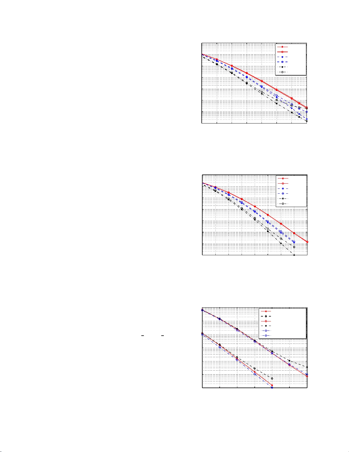
1 Smoothed SVD-based Beamforming for FBMC/OQAM Systems Based on Frequenc y Spreading Y u Qiu, Daiming Qu, Da C hen, and T ao Jiang, Senior Member , IEEE Abstract —The combination of singular v alue decomposition (SVD)-based beamf orming and fil ter bank multicarrier with offset quadrature a mplitud e mo dulation (FBM C/OQAM) has not been su ccessful to date. Th e diffi culty of this combination is that, the beamformer s may experience signifi cant chan ges between adjacent subchannels, theref ore destroy the orthogonality among FBMC/OQAM real-v alued symbols, e ven under channels with moderate fr equency selectiv ity . In this paper , we addr ess this problem fr om two aspects: i) an S V D - F S-FBMC arc hitecture is adopted to sup port beamf orming with fin er granularity in frequency domain, based on the frequency spreading FBMC (FS-FBMC) structure, i . e., beamf orming on FS-FBMC tones rather than on subchannels; ii) criterion and methods ar e proposed to smooth the beamformer s from tone to tone. The proposed finer beam forming and smoothing greatly i mp ro ve the smoothness of beamfor mers, theref ore effectively sup p ress the leaked ICI/ISI. Simulations are cond ucted under the scenario of IEEE 802.11 n wireless LAN. Results sho w that the proposed SVD-FS-FB M C system shares close BER perfo rmance with its orthogonal frequency division mu l tiplexing (OFDM) coun terpart under the frequency selective channels. Index T erms —Filt er b ank mul ticarrier (FBMC), fr equency spreading FB MC (FS-FBM C), MIMO, p recoding, singular value decomposition (SVD), frequency selective channel. I . I N T RO D U C T I O N Filter b ank m ulticarrier with offset quad rature amplitude modulatio n (FBMC/OQAM) [1]–[12] is considered as a promising alternative to the co n ventional or thogon al frequ e ncy division multiplexing (OFDM) technique [13], [14]. Howev er, integration o f multiple-input multiple-outpu t (MIMO) tech - niques with FBMC/OQAM, in genera l, is more com plicated than with OFDM. T h anks to the add ing of CP , a subchannel (subcarrier band) is exactly flat an d independen t from other subchann els in OFDM systems. Thu s, MIMO precoding and equalization can be taken on each subchan nel independen tly , without leading to any inter-carrier interferen ce (ICI) or inter- symbol interferen ce (ISI ). Howev er, without CP , the MIMO precod in g and equalization of FBMC systems are more com- plicated and co uld lead to considerable ICI/ISI u nder fre- quency selecti ve chann els, d ue to th e fact that FBMC /OQAM Y u Qiu, Daiming Qu (corresponding author), Da Chen, and T ao Jiang are with the School of Electronics Informatio n a nd Communication s, Huaz hong Uni versit y of Science and T echnology , Wuh an, 430074, P . R. China (e-mail: qudaiming @hust.edu.cn). This work is supported in part by the National Natural Science Foundation of China (61571200, 61701186) and the open research fund of National Mo- bile Communicati ons Research Laboratory , Southeast Univ ersity (2014D09). is a non-o rthogo nal wa veform (FBMC/OQAM sym bols are orthog onal with each other only in the real do main [1]–[3]) . In FBMC/OQAM systems, the real and imaginary parts of QAM symbo l are separate d and transm itted as p ulse amplitud e modulated (P AM) symbols. There exists ICI/ISI interference between the P AM sym bols in the form of imaginary inter- ference. ICI/ISI-fr ee symbols are o btained only after channel equalization and taking the r eal par ts, e.g., see [1]–[3], [ 10] for details. The combination of MIMO and FBMC/OQAM is a tri vial task in channels with h igh co herence ban dwidth, which is almost equiv alent to MIMO-OFDM systems. While for the f requen cy selective channe ls, without carefully d esign, the beamf o rming matrices could differ dramatically between adjacent sub channels, and the imagina r y interfe r ence from one subchan nel could be leaked into adjacent subchanne ls as real in terferen c e , therefore de stroy the orthogo nality among FBMC/OQAM P AM symbo ls in the real domain [15]. A ware of th e ICI/ISI in ter ference, some studie s [16]–[20] attempt to co nstrain this inter ference by caref ul design of precod in g as well as equalization for MIMO-FBMC/OQAM systems. In [16], two MIMO-FBMC precoding /equalization schemes were designed to maximize the sign al to leak age plus noise ratio (SLNR) and the signal to in te r ference plu s noise ratio (SINR), respectively . Criterion of minimizing the sum mean square err or was ad opted in [ 17]. The coordinated beamfor ming technique was applied in MIMO-FBMC/OQAM systems [18], where the precodin g and deco ding matr ix are computed jointly and iterativ ely . A two-step me th od was propo sed in [19], wh ere the precoders are first optimized to maximize the SLNR gi ven the equalizers and then, the equal- izers are designed accord ing to the minimum mean square error (MMSE) cr iterion while fixing the precoders. Althoug h the ICI/ISI interfere nce is suppressed, error performan ce lo ss or significantly increased complexity , compar e d with their OFDM co unterp a r ts, are observed with the aforemen tioned MIMO-FBMC/OQAM schemes. V ery recently , a novel ar - chitecture was proposed to approxim a te an ideal frequen cy selecti ve precod er and linear receiver b y T aylor expansion , exploiting the structure of the analysis and syn thesis filter banks [21]. This architectur e was shown to be very promising , howe ver more results are needed to reveal its full potential. Smoothing of the precoders is propo sed in [22], which keeps the phase of o ne precoder compo nent con stant accr oss subcar- riers. However , the p h ase con tinuity crierion is not effectiv e when this p recoder comp onent crosses zero and ch a nges its sign. A more thorou gh revie w of MIMO-FBMC/OQAM 2 precod in g/beamf o rming tec h niques, in c lu ding tho se for multi- user MIMO [23]–[25], could b e found in [26]. Most of the works o n percoding/b eamfor m ing of MIMO- FBMC und er frequen cy selective channels assume ployp hase network implemen tatio n o f FBMC [27], [28]. In this pap er , we focus on another typ e of implementatio n, namely freq uency spreading FBMC (FS-FBMC), which has attr acted wide at- tention in rec e n t years [30]–[ 41]. MIMO methods specifically designed for this type o f implementation are in need. Singular value dec o mposition (SVD) based beamformin g, adopted in the IEEE 802.11 n wireless LAN standard, yield s maximum likelihood perfo rmance with simple linear tran smit and recei ve beamfo rmers fo r MIMO-OFDM systems [ 29]. Unfortu n ately , perfect comb ination with SVD b eamfor ming is not yet av ailable fo r FBMC/OQAM systems. In this pa p er , we propo se a novel SVD-FS-FBMC schem e that is robust to chan - nel freque ncy selectivity . While trad itional beamform ing of MIMO-FBMC are taken on per-subchannel basis, th e pro posed scheme enab les beam f orming of finer granu larity in frequen cy by using the frequ ency spreading FBMC (FS-FBMC) structu re [30]–[34], i.e. , b eamform ing on FS-FBMC tones. W e further propo se two m ethods, na mely phase factor op timization and orthog onal iteration, to smoo th the SVD-based beamfor mers from tone to tone. The criterion of smoothing proposed is to minimize the Euclidean distance b etween ad jacent beam- former s. The p roposed fine r b eamform ing an d smoothing methods gr eatly improve th e smoothne ss of b eamform ers, therefor e effecti vely sup press the leaked ICI/ISI from adjacent subchann els. Simulations are conducted u nder th e scenario of IEEE 802.11 n wireless L AN and the results sho w that the propo sed SVD-FS-FBMC system performs closely with its OFDM co u nterpar t und er the IEEE 802.1 1 n Chan nel Models. Our prelimina ry results on this subject have been r e p orted in [34]. The fo llowing notation s ar e used in this paper . Bold lower- case letter s den ote column vectors. Bold upp er-case letters are used for matr ic e s. Th e superscripts ( · ) T , ( · ) ∗ , ( · ) H , an d ( · ) † represent the transpose, c o njugate, Hermitian tr anspose, and Moor e-Penrose pseudo -in verse, respe c ti vely . ℜ{·} and ℑ{·} de n ote the real and imaginar y p arts, respectively . E [ · ] stands for the expectation. || · || 2 denotes vector o r matrix 2 - norm, || · || F denotes th e matrix Frobenius-nor m, wh enever the particu lar choice of no rm is unimp ortant, || · || is u sed. Function sin and arccos o f a matrix is app lied element- wisely in this paper . Finally , j = √ − 1 . I I . S Y S T E M M O D E L S & I C I / I S I O F S V D - F B M C / O Q A M A. FBMC/OQAM System Model Fig. 1 presents the equ ivalent baseband block diag ram o f an FBMC/OQAM system. It consists of M subc a rriers with subcarrier spa cing 1 /T , where T is the interval between the com plex-valued sym bols in time. Each complex-valued symbol is par titioned into a pair of real-valued P AM symb ols. The P AM sym b ol at the frequ e n cy-time ind ex ( m, n ) is denoted by a m,n , wh e re m is the frequ e n cy/subchann el index and n is the time ind ex. Moreover , a m, 2 ˆ n and a m, 2 ˆ n +1 , with integer ˆ n , are real and imaginar y p arts of a QAM symbol and are T / 2 spaced in time. W ith a sampling interval of T / M , the filter bank prototy pe filter has the discrete time impulse respon se g ( i ) , which we assum e only have n on-zero coefficients f or 0 < i ≤ K M − 1 , wh ere K is a positive integer . W e further assume that g ( i ) is an e ven-symmetr ic pulse, i.e., g ( i ) = g ( K M − i ) . The discrete-time baseband equ iv alent of an FBMC/OQAM signal may be presented a s [2], [42] x ( i ) = M − 1 X m =0 X n ∈ Z a m,n g ( i − n M 2 ) e j 2 πmi M e j π ( m + n ) 2 | {z } g m,n ( i ) , (1) where g m,n ( i ) is the pulse of the ( m, n ) -th P AM sym bol. When an FBMC/OQAM signal is tr ansmitted through a ch an- nel that varies slo wly with time and its delay spr e ad is signif- icantly shorter than th e symbol interval, the chann el transfer function over e a ch subch annel m ay be approximated b y a flat gain. Let H m,n denote th is gain for the m -th subc hannel at the n -th time index. W ith the slow varying assumption, we omit th e subscript n from H m,n for simplicity of presentatio n. Then, the m 0 th outpu t of the r eceiv er analysis filter bank at the n 0 th time index is obtain ed a s, [2 ], [42], r m 0 ,n 0 = ∞ X i = −∞ g ∗ m 0 ,n 0 ( i ) M − 1 X m =0 X n ∈ Z H m a m,n g m,n ( i ) ≈ H m 0 a m 0 ,n 0 + H m 0 X ( m,n ) 6 =( m 0 ,n 0 ) a m,n ζ m 0 ,n 0 m,n (2) where ζ m 0 ,n 0 m,n = ∞ X i = −∞ g ∗ m 0 ,n 0 ( i ) g m,n ( i ) . (3) It is n otew orth y that f or a well-designed proto type filter g ( i ) , ζ m 0 ,n 0 m,n = 1 wh en ( m, n ) = ( m 0 , n 0 ) , a nd is zero or a pure imaginary value when ( m, n ) 6 = ( m 0 , n 0 ) , e.g ., see [1]. T o be more specific, ζ m 0 ,n 0 m,n , for ( m, n ) 6 = ( m 0 , n 0 ) , represents the imaginary interfere nce to a m,n , which cou ld be removed by taking the real p art after channel equalization. B. SVD- based MIMO Bea mforming W e consider a MIMO system equipped with N t transmit antennas a n d N r receive antennas, which suppor ts L parallel streams. Th e SVD decomp osition of th e chan nel H ∈ C N r × N t is: H = UDV H , (4) where V ∈ C N t × N t and U ∈ C N r × N r are unitary matrices, and D is an N r -by- N t rectangu la r d iagonal m atrix con taining ( λ 1 , λ 2 . . . ) as diagonal elements, where λ 1 , λ 2 . . . deno te the singular values that are sorted in de scen ding ord er and are real-valued. When L = N t = N r , the transmit beamfo rmer and receive beamfo rmer are simply V and U H , resp ectiv ely . When L < N t or L < N r , they are submatrices of V and U H , respectively , correspondin g to the L largest singular values. For clarity of notation s, we a buse the n otations V a nd/or U H and let the m also represent the beamfo rmers when L < N t or L < N r in the rest of this paper, then V ∈ C N t × L and 3 Fig. 1. T he equiv ale nt base band block diagram of an FBMC/OQAM system. U H ∈ C L × N r . W ith the transmit beamforming an d MIMO channel, the signal at the receiver is y = HVs + n , (5) where s is the symb ols to be transmitted and n is the recei ve noise vector ( y , s and n are N r × 1 , L × 1 and N r × 1 vectors, respectively). The signal after recei ve be amform in g is r = U H y = U H ( HVs + n ) = Ds + e n , (6) where e n = U H n ( r and e n are L × 1 vectors). Clearly , the transmitted symbols are recovered with noneq u al gains [43], and there is no interference am ong streams. C. Straightfo rwar d Comb ination of S VD and FBMC/OQAM In this subsection , we present the model o f straig htforward combinatio n of SVD and FBMC/OQAM and discuss abo ut the interf erence leakage pro b lem. Combinin g the models in subsection I I-A and II-B, th e tra nsmitted signa l of the SVD- FBMC/OQAM is represented by a sequ e nce of vector s x ( i ) = [ x 1 ( i ) x 2 ( i ) · · · x N t ( i )] T as x ( i ) = M − 1 X m =0 X n ∈ Z V m a m,n g m,n ( i ) , (7) where a m,n = [ a 1 m,n a 2 m,n · · · a L m,n ] T is the symbol vector to be transmitted, and g m,n ( i ) is the frequen cy-tim e shifted version o f prototy pe filter g ( i ) (see (1)), V m ∈ C N t × L denotes the beamf o rming matr ix for the m -th subchan n el. Assuming nearly flat fadin g acr oss th e subcarrier b and (the b a ndwidth of sub channe l), the received signal at the o utput of analysis filters for T ime n 0 and Subchann el m 0 is r m 0 ,n 0 ≈ M − 1 X m =0 X n ∈ Z U H m 0 H m V m a m,n ∞ X i = −∞ g ∗ m 0 ,n 0 ( i ) g m,n ( i ) = M − 1 X m =0 X n ∈ Z U H m 0 H m V m a m,n ζ m 0 ,n 0 m,n = D m 0 a m 0 ,n 0 + X ( m,n ) 6 =( m 0 ,n 0 ) U H m 0 H m V m a m,n ζ m 0 ,n 0 m,n , (8) where H m ∈ C N r × N t is th e MIMO chan n el respon se of Subchann el m , U H m 0 ∈ C L × N r is the r eceive beamformer for the m 0 -th subchann el. Clearly , the first term of (8) is the recovered symbols and the second term is the ICI/ISI interferen ce. If H m 0 ≈ H m and V m 0 ≈ V m for sub channels adjacent to m 0 , we h av e U H m 0 H m V m ≈ D m 0 , and th e ISI/ICI ter m is app roximately imag inary an d could be removed by taking the r eal part of r m 0 ,n 0 (recall that D m 0 is real- valued). However , this does n ot work e ven under channels with mod erate frequency selecti vity . The reason is th a t: the transmit an d r e ceiv e b eamform er may exper ience significant changes between adjacent subchan nels d ue to channel v aria- tion, then U H m 0 H m V m is not real- valued and the ISI/ICI term is no lon ger pu re imaginary , wh ich results in leaked ICI/ISI interferen ce into the real part of r m 0 ,n 0 . I I I . T H E F I N E R B E A M F O R M I N G A R C H I T E C T U R E In this section, we p ropose fin er beamform ing for FBMC/OQAM, here finer bea m formin g means beamfor ming with finer granularity in f requen cy domain. As d iscussed in the above section, th e straig h tforward SVD-FBMC/OQAM sys- tems beamform at the subchannel level, i.e. , each su b channe l has its o wn transmit and receiv e beamf o rmer . T o enable a finer granularity , we adopt the FS-FBMC structure [30]–[33], and beamfor mers are de sig ned at each tone o f FS-FBMC. The propo sed fin er be a mformin g provid es a basic ar c h itecture to support smoother changes f rom subchann el to subchan nel. A. F r equency Spr eading FBMC (FS-FBMC) The FS-FBMC structu re, a special form of the fast con- volution impleme n tation o f filter banks [ 4 4]–[49], u ses fre- quency spreadin g/despread ing to imp lement the filtering in the frequen cy do m ain for FBMC/OQAM systems. In FS-FBMC, FFT/IFFT is taken at the leng th of K M . L e t G ( k ) denote the FFT of a segment of g ( i ) in the range of 0 ≤ i ≤ K M − 1 , where 0 ≤ k ≤ K M − 1 is the index o f FS-FBMC tones. W e assume that G ( k ) has 2 P − 1 non -negligible tones that center around the zero-th tone, where P is a positiv e integer . Let G ( n 0 ) m,n ( k ) d e note the FFT of a segment of g m,n ( i ) in the range of n 0 M / 2 ≤ i ≤ n 0 M / 2 + K M − 1 , which is the portion of g m,n ( i ) that falls inside the n 0 -th sliding win dow . The superscript ( n 0 ) is to emphasize that the FFT is taken at the n 0 -th window . T hen, the filtering at the n -th time ind ex is implemented in the frequency do main by sp r eading the P AM symbols with G ( n ) m,n ( k ) as b n ( k ) = M − 1 X m =0 a m,n G ( n ) m,n ( k ) , (9) 4 where G ( n ) m,n ( k ) is the FFT of the non -zero part o f pulse g m,n ( i ) , i.e., a t the n -th wind ow . And, the outp ut o f the frequen cy spr eading is fed to the IFFT transformatio n to o btain the time domain samples of the n - th time ind ex as x n ( i ) = K M − 1 X k =0 b n ( k ) e j 2 πk ( i − nM / 2) K M , nM 2 ≤ i ≤ nM 2 + K M − 1 0 , else . (10) Then, the transmitted time sequence is obtained by accumu- lation over all symbols as x ( i ) = X n ∈ Z x n ( i ) . (11) At the receiver , a sliding window is employed to select K M samples ev ery M / 2 samples, which are fed to an FFT module. Then, the transmitted P AM symbols are recovered throug h equ alization and freq uency despre ading. Mo re details of FS-FBMC transmission could b e found in [50]. B. F iner SVD Beamforming Fig. 2 presents th e tra nsmitter of the pr o posed finer SVD- FS-FBMC, wher e V k ∈ C N t × L is the beam formin g matrix for th e k - th FS-FBMC tone, and V k = [ v 1 k v 2 k · · · v L k ] , h ere v l k denotes the b eamfor m ing vector for the l -th stream . The beamfor med signals on all tran smit an tennas for the k -th to n e and n -th time index is giv en by an N t -by-1 vector b n ( k ) = V k M − 1 X m =0 a m,n G ( n ) m,n ( k ) . (12) Then, the samples on all transmit antennas for the n -th time index is o btained by IFFT x n ( i ) = K M − 1 X k =0 b n ( k ) e j 2 πk ( i − nM / 2) K M , nM 2 ≤ i ≤ nM 2 + K M − 1 0 , else , (13) where x n ( i ) is an N t -by- 1 vector . After accu mulation over all symbols, the transmitted sig- nals on all antennas are r epresented by the following vector sequence x ( i ) = X n ∈ Z x n ( i ) . (14) Fig. 3 pr e sen ts the receiv er of the p ropo sed SVD-FS-FBMC, where U H k ∈ C L × N r is the beamfo rming matrix fo r the k - th FS-FBMC ton e, and U H k = [( u 1 k ) H ( u 2 k ) H ··· ( u L k ) H ] , her e ( u l k ) H denotes the recei ve beamforming vector for the l - th stream. Let N r -by-1 vector y ( i ) den o te the i -th receiv ed sam ples o n all receive antennas, and y ( n 0 ) ( i ) ( 0 ≤ i ≤ K M − 1 ) den ote the selected K M samples by the n 0 -th sliding window , i.e., S/P S/P Freq. spread ing Freq. spread ing . . . . . . . . . IFFT P/S + overlap/ sum P/S + overlap/ sum . . . IFFT . . . . . . . . . Antenna 1 Antenna t N Stream 1 Stream L 1 V 2 V KM V . . . . . . . . . . . . D E [ Filtering Filtering Fig. 2. T he transmitter of the proposed SVD-FS-FBMC scheme. Sliding window + S/P . . . . . . FFT Singular value equaliza tion Freq. desprea ding FFT . . . Singular value equaliza tion Freq. desprea ding P/S P/S Stream 1 Stream Antenna 1 Antenna . . . . . . . . . . . . r N H 1 U L H 2 U H KM U Sliding window + S/P . . . . . . . . . . . . . . . . . . Filtering Filtering y b s s a ~ ~ ~ - Fig. 3. T he recei ver of the proposed SVD-FS-FBMC scheme. y ( n 0 ) ( i ) = y ( i + n 0 M / 2) , fo r 0 ≤ i ≤ K M − 1 . T aking FFT of y ( n 0 ) ( i ) , we obtain e b ( n 0 ) ( k ) = 1 K M K M − 1 X i =0 y ( n 0 ) ( i ) e − j 2 πki K M , 0 ≤ k ≤ K M − 1 . (15) Applying the receive beam former, we have the signals received on the k -th tone e s ( n 0 ) ( k ) = U H k e b ( n 0 ) ( k ) , (16) where e s ( n 0 ) ( k ) is an L -by- 1 vector that holds the samples of all streams. Noting that different tones and streams may h ave different singu la r v alues, an eq u alizer is req u ired at each tone for each stream . The eq ualizers for the k -th ton e is rep resented by an L -by- L diagonal matrix E k = dia g E 1 k , E 2 k , . . . , E L k , where E l k is the e qualizer for Stream l and T one k . If it is a zero fo rcing (ZF) equalization, E l k = 1 /λ l k . Th en, the equalized signal is obtained as s ( n 0 ) ( k ) = E k e s ( n 0 ) ( k ) . (17) Finally , despreadin g is a pplied to o b tain the P AM symbols at the m 0 -th subchan nel and n 0 -th time index e a m 0 ,n 0 = K M − 1 X k =0 G ( n 0 ) ∗ m 0 ,n 0 ( k ) s ( n 0 ) ( k ) = K M − 1 X k =0 G ( n 0 ) ∗ m 0 ,n 0 ( k ) E k U H k e b ( n 0 ) ( k ) . (18) 5 Under the assumptio n that E k , U k , H k and V k are nearly flat, i.e., they vary slo wly , across the subcarrier band, e a m 0 ,n 0 ≈ a m 0 ,n 0 + X ( m,n ) 6 =( m 0 ,n 0 ) a m,n K M − 1 X k =0 ζ m 0 ,n 0 m,n + K M − 1 X k =0 G ( n 0 ) ∗ m 0 ,n 0 ( k ) E k U H k n ( n 0 ) ( k ) , (19) where n ( n 0 ) ( k ) is FFT of the noise with y ( n 0 ) ( i ) . Proof of this equ ation is pr esented in th e Appendix . Clearly , the first term of (19) is th e transmitted P AM symbols, and the second term is the ICI/ISI interf e r ence tha t is pure imaginary under the nearly- flat assumption and could be removed by taking the real part. Obviously , the com plexity of beamf orming in the proposed SVD-FS-FBMC system is rough ly p ropor tional to the number of tones per sub channel, i.e. K . When K = 1 , i.e. without frequen cy spreading and despread ing, the proposed SVD-FS- FBMC is exactly th e same a s th a t of SVD-OFDM with the same su bchann el number M . Theref ore, the com plexity of beamfor ming in th e pro posed SVD-FS-FBMC is K times th at of the SVD-OFDM with the same subch annel number M . Compared with the straigh tforward SVD-FBMC/OQAM giv en in Section II- C, the m ajor improvement by th e finer beamfor ming is that it allows smoother tra n sition of beam- former s. I V . B O U N D S O N T H E E U C L I D E A N D I S TA N C E B E T W E E N A D JA C E N T B E A M F O R M I N G M AT R I C E S The deriv ation of the finer SVD-FS-FBMC in Subsection III-B is under the assumption that H k is nearly flat across the subcarrier bandwidth , as well as E k , U k and V k . In this section, we will show that E k , U k and V k that are nea r ly flat are av ailable, i.e., they can be bounded in Euclidean distance between a djacent to nes, as long as H k is near ly flat. The reasoning here is based o n th e pertur bation theory for SVD decomp o sition [54]– [56]. This section also ser ves as a justification to the smoothing criterion proposed in Section V, wh ich min imizes th e E u- clidean distance between beamformer s of adjacent tones. As the ch a nnel is assumed to be nearly flat, H k can be written as H k = H k − 1 + ∆ H k , (20) where ∆ H k is an N r -by- N t matrix, and || ∆ H k || 2 ≪ || H k − 1 || 2 . Then , the W eyl theo r em [55] giv es a bound on the difference between the singular values of H k and H k − 1 . Theorem 1 (W eyl). | λ l k − λ l k − 1 | ≤ || ∆ H k || 2 , l = 1 , · · · , L. (21) Due to th e W eyl theorem, when || ∆ H k || 2 is small, the difference between λ l k and λ l k − 1 is also small. Th us, E k can be assumed nearly flat. T o bound the dif ferenc e between V k and V k − 1 as well as that between U k and U k − 1 , we take use of the W ed in theore m [56] belo w . W ith the W edin’ s theorem, we will show that the eig e nspaces spanne d by V l k and V l k − 1 are clo se, wher e V l k = [ v 1 k , · · · , v l k ] . W e will also show that V l − 1 k and V l − 1 k − 1 are c lo se. Th en, we reach the conclusion that the eigenspaces spanned by v l k and v l k − 1 are close. Similarly , subspaces u l k and u l k − 1 are close as well. In stead of directly bounding the Euclidean distance be- tween the singular v ectors, the W edin the o rem gi ves a boun d on ang les between the subspaces spanned by th e singular vectors. Let L an d M in C N × l have full colum n ran k l , the angle matrix from L to M is defined as [56] Θ ( L , M ) = arccos(( L H L ) − 1 2 L H M ( M H M ) − 1 M H L ( L H L ) − 1 2 ) − 1 2 . Then, || sin Θ ( L , M ) || F giv es a measure of h ow much the subspaces of L and M are sepa rated in angle [56]. W ith the definition, the W edin theore m is given as Theorem 2 (W edin). If ther e is a δ > 0 , such that min 1 ≤ i ≤ l,j ≥ l +1 | λ i k − λ j k − 1 | ≥ δ, (22) and λ l k ≥ δ, (23) then q || sin Θ ( V l k , V l k − 1 ) || 2 F + || sin Θ ( U l k , U l k − 1 ) || 2 F ≤ q || R l R || 2 F + || R l L || 2 F δ , (24) wher e R l R = H k − 1 V l k − U l k Diag( λ 1 k , · · · , λ l k ) R l L = H H k − 1 U l k − V l k Diag( λ 1 k , · · · , λ l k ) . (25) The bound ( 24) is a combined bo u nd. Th e left-hand sid e combines the angles for the left and r ight singular su bspace. The right-hand side comb ines wha t might be called right an d left residuals. The condition s (2 2) and (23) are separation condition s. The first says that λ 1 k , · · · , λ l k are separa ted from λ l +1 k − 1 , · · · . The secon d condition says that the sing u lar value λ l k are separated from th e g h ost sing ular values (singu lar values very clo se to zero). In additio n to th e W edin th eorem, the following ine q ualities hold [54] || R l R || ≤ || ∆ H k || , || R l L || ≤ || ∆ H k || . (26) Combining the W edin the o rem and (26), it is clear that, subspaces U l k and V l k are stab le, i.e., th e ang les between U l k and U l k − 1 , p lus angles between V l k and V l k − 1 , are bo unded by (24), und er the conditions (22) and (23). In othe r words, subspaces V l k and V l k − 1 subspaces U l k and U l k − 1 are close to each other . Similarly , if the seperation condition s are satisfied for l − 1 , subspaces V l − 1 k and V l − 1 k − 1 are close to each othe r . Since V l k = [ V l − 1 k v l k ] and V l k − 1 = [ V l − 1 k − 1 v l k − 1 ] , we can say that v l k and v l k − 1 are close, me asured by angles between subspaces. Similarly , subspaces u l k and u l k − 1 are close as well. 6 The b ounde d ang les between subspaces me a ns that, given any v l k − 1 (or u l k − 1 ), a vector with bound ed Euclidean distan c e to v l k − 1 (or u l k − 1 ) is a vailable in sub space v l k (or u l k ). Concluding th e discussion above, when H k is assum ed nearly flat, U k and V k that are near ly flat are av ailable, i.e., beamfor mers of adjacent to nes can b e b ounded in Eu clidean distance, if all co rrespond ing singu lar values satisfy the sepa- ration condition s (22) and ( 23). V . S M O O T H I N G O F B E A M F O R M E R S In Section IV, the th eories show th at E k , U k and V k can be bound ed in Eu clidean distance between adjac e nt tones, as lo ng as H k is nearly flat and the separation conditions are satisfied for singular v alues of all stre ams. Howe ver , unfortun a tely , not every SVD algorith m generates U k and V k ’ s that are bound ed in Euclidean distance acro ss adjac e nt k ’ s a s required by the proposed architectu re. The reason is that: the SVD decomp o sition is n o t unique, it may pr oduce more than one set of singular vectors th at span the same space but are different [52]. A. Smo othing Cr iterion and Phase F actor Optimization T o deal with this p roblem, we propose in this sub section a smoothing criterion and method to smooth the outpu t of any g iven SVD algorithm so th a t it satisfies th e nearly-flat requirem ent. The idea here is as follows : W e smooth the output of the g iv en SVD algor ithm, denote d by ˆ V k , to obtain V k such that its Euclidea n distance to V k − 1 is b ounde d as given in Section I V. The criter io n of min imizing the distance of adjacent beamfo rmers is intuitive, due to the fact that Euclidean distance, i.e., Eu clidean dif feren c e of adjacen t vectors, is a measure of first-order smo othness for vector function s. In additio n, the criter ion is known to be effectiv e thanks to the discussion in Section IV. Running this op eration from the b eginning to the end of the activ e fre quency tones, a sequence of sm oothed beamform ers is obtained. It is worth mentionin g here that we have also attempted to optimize the second-o rder smoo thness, howe ver no further ob servable ga in over the fir st-order smoothne ss optimization was obtain ed. The reason is that the chann el frequen cy response is rather smooth with the finer beamf orming and second-or d er smoo thness or above is unnec e ssary , und er the system param eters and ch annel models considered in Section VI . It is assum ed that ˆ v l k is the l - th r ight singular vector gi ven by th e SVD algorith m , co rrespond ing to the sing ular value ˆ λ l k of H k , here the hat ˆ is to emp hasize that ˆ v l k and ˆ λ l k are the outputs of the SVD algor ithm b efore smooth in g. T aking ˆ v l k as the input, after smoothing, v l k is output as the b eamform er . The su b space spann ed by ˆ v l k can b e rep resented by a set Π ( ˆ v l k ) = { β ˆ v l k e j θ | β ∈ R , θ ∈ [0 , 2 π ) } . If ˆ λ l k satisfy the separation conditio ns, d istance from Π ( ˆ v l k ) to Π ( v l k − 1 ) is bound ed due to the W ed in th eorem, here v l k − 1 is the smooth e d beamfor mer of the ( k − 1) -th frequ ency tone. Therefore, a vector that has a bounde d Euclidean distance to v l k − 1 is av ailable in Π ( ˆ v l k ) . Then , the problem of smoothin g the SVD output is solved by v l k = e j θ ∗ ˆ v l k , (27) where e j θ ∗ is a phase factor that min imizes the distan ce from e j θ ˆ v l k to v l k − 1 , i.e., θ ∗ = arg m in θ {|| e j θ ˆ v l k − v l k − 1 || 2 } . (28) The solution to the phase factor optimizatio n p roblem is e j θ ∗ = ( ˆ v l k ) H v l k − 1 | ( ˆ v l k ) H v l k − 1 | . (29) Combining (27) and (29), we h ave the smoo thed output as v l k = ( ˆ v l k ) H v l k − 1 | ( ˆ v l k ) H v l k − 1 | ˆ v l k . (30) When two singu lar values bec o me very close to each other, the bound given by the W edin theore m is not close to zero ev en when th e channel frequency respo n se is smooth, then smoothne ss between adjacent beamforme rs canno t be guar- anteed. Still, smo othing is need ed to minimize the Euclidian distance of v l k and v l k − 1 for all l ’ s. While smoothing the SVD o utput in this ca se, a special prob le m needs to b e treated carefully . The problem is the am biguity in p airing one fro m { ˆ v l k , . . . , ˆ v L k } with v l k − 1 , which is explained in the following. When ˆ λ l k ≈ λ l k − 1 and it is separated from other singu lar values, there is no doubt that ˆ v l k should be paired with v l k − 1 . Howe ver , when there are multiple singular values of the k -th frequency tone approx im ate λ l k − 1 , i.e., ˆ λ l 1 k ≈ . . . ≈ ˆ λ l m k ≈ λ l k − 1 , where m is the num ber of singular values tha t ar e close to λ l k − 1 , there has to b e a method to d etermine which of ˆ λ l 1 k , . . . , ˆ λ l m k ( ˆ v l 1 k , . . . , ˆ v l m k ) sho uld be paired with λ l k − 1 ( v l k − 1 ), i.e., wh ich one belo ngs to th e l -th stream. T o resolve this ambig uity , w e measure the subspace distance from ˆ v l i k to v l k − 1 , f o r l 1 , . . . , l m , and select the one with the minimum subspace distance to pair with v l k − 1 . The su bspace distance of two vectors, ˆ v l i k and ˆ v l k − 1 in our d iscussion, is defined as [51] d l i = || ˆ v l i k ( ˆ v l i k ) H − v l k − 1 ( v l k − 1 ) H || 2 , (31) and let l ∗ = arg min l i ∈ l 1 ,...,l m { d l i } . (32) Then, ˆ λ l ∗ k is taken as the singu lar value of Stre a m l , and ˆ v l ∗ k is smoothed to generate th e beamform er as λ l k = ˆ λ l ∗ k v l k = ( ˆ v l ∗ k ) H v l k − 1 | ( ˆ v l ∗ k ) H v l k − 1 | ˆ v l ∗ k . (33) B. Smo othing by Orthogon al I teration In this sub section, we intro duce the orth ogonal iteration method [51] for smooth ing, which spon taneously fo llows the propo sed smoo thing criterion due to its iterative n ature. Compared with the phase factor op tim ization meth od, the orthog onal iteration enjoys lower compu tational complexity . The orthogon al iteration method has been u sed in [52] to provide smooth beamforming for an OFDM system to enable channel state information ( CSI) smoothing . 7 As we know , V k is the right singular vectors of H k , as well as the eigenv ectors of A k = H H k H k , which can be fou nd by performin g the following iteration from an initial matrix Q (0) ∈ C N t × L with orthon o rmal column s B ( i ) = A k Q ( i − 1) , i = 1 , 2 , · · · QR decomp osition : B ( i ) = Q ( i ) R ( i ) , (34) where i denotes the iter ation index and N iter is the total number of iterations. According to [5 2], R ( i ) conv erges to a diag onal matrix con taining the eigenv alues o f A k , and Q ( i ) conv erges to an orthonorm al basis for the d o minant su bspace of dimension L . For a beamf orming that is smooth from T one k − 1 to k , V k − 1 could serve as the initial Q (0) , and the outp u t is V k = Q ( N iter ) . It will be shown in the next section th a t very f ew iterations are ne eded to obtain a satisf actory V k , which ensures smoothness from V k − 1 to V k . The complete algorithm is presented in Alg orithm 1. Algorithm 1: Ortho gonal Iteration for Smo oth Beamforming 1: Initialize V 0 = SVD( H 0 ) ( SVD( · ) stan ds f or an arbitrary SVD algorithm); 2: for k = 1 : K M − 1 do 3: A k = H H k H k ; 4: V k = V k − 1 ; 5: for i = 1 : N iter do 6: B k = A k V k ; 7: Update V k using the fo llowing QR d ecompo sition: B k = V k R k ; 8: end f or 9: D k = SQR T( R k ) ( SQR T( · ) stands for th e squa r e root of an diagonal matrix); 10: end for V I . S I M U L A T I O N R E S U LT S In this section, we e valuate the performan c e of the finer and sm o othed SVD beamfo rming for FBMC/OQAM that was propo sed in this paper , throug h computer simulatio ns. W e compare the proposed SVD-FS-FBMC system with an SVD- OFDM system, u nder a setup similar to the IEEE 802.11 n wireless LAN standar d . Than ks to orthogon ality among sub - channels, the error p erform ance of SVD-OFDM is the upper bound of the proposed SVD- FS-FBMC, if the CP overhead of OFDM is ignored . Th e presented results re veal excellen t perfor mance of our prop osed m ethod, which can co m pete with OFDM and give clo se BER re su lts with 64-QAM constella- tion, un der c h annel mod els of the IEEE 802.11 n standard . As shown by T able I , the Cha nnel Model D, E, a n d F of the IE EE 802.1 1n stan dard h av e r elativ ely large m aximum delay spread , when normalized by the OFDM symbo l duration ( 3200 ns), which r esult in stro ng f requen cy selectivity . E specially for the Channel Mo del F , the m aximum delay spread is ev en lo nger than the CP defined in the stand ard ( 800 ns). For th e simulations presented in this section, the fo llowing parameters are used fo r both SVD-FS-FBMC and SVD- OFDM systems. The MIMO system is configu red as N t = T ABLE I M A X I M U M D E L A Y S P R E A D O F T H E C H A N N E L M O D E L S Channel Model Maximum delay spread (ns) Maximum delay spread normaliz ed by the OFDM symbol duration D 390 12.2% E 730 22.8% F 1050 32.8% N r = L = 2 . There are M = 64 subcar riers, a n d the subcarrier spacing is 312 . 5 kHz. Among the 64 subcarriers, 48 are active subcarriers mo dulated with 16-QAM or 64- QAM constellations. W e app ly no power allocation among subcarriers a n d streams in the simu lation, i.e., a ll stre a ms (and 48 subcarrier s) have equal transmit power . For chann el cod in g, we use co n volutional cod e of rate 2 / 3 and constraint length 7 . A rando m inter leav er is applied after the codin g. Ea c h d ata frame consists of 7 FBMC/OFDM symbols (each consists of 48 OQAM/QAM symbols). The FBMC systems em ploy the PHYD Y AS filter [53], and th e overlapp in g factor K is 4 . With the FFT size of 4 M , th e filter has 7 n o n-negligible tones, i.e., P = 4 . For the sin gular value equalization, a ZF equalizer is employed at receiver o f the p ropo sed SVD-FS-FBMC. And , we set N iter = 3 for the orthogon al iteration me th od. T he SNR in the simulation is defined a s: SNR ∆ = N t σ 2 a σ 2 h /σ 2 n , where σ 2 a , σ 2 h and σ 2 n are the expected signal power of each transmit an tenna, expected chan nel power gain between a pair of transmit an d receive an tennas, and expected A WGN no ise power of each receive anten na, re sp ectiv ely , o n each active subchann el. In m ost of the following figur es, we p r esent the perfo rmance of the prop osed SVD-FS-FBMC system with the orthog onal iteration of three itera tions. T o ju stify the use of orthogon al iteration and N iter = 3 , BER performance com parison be- tween th e orthog onal iteration of different iterations and phase factor o ptimization is presented in Section VI-C, followed b y complexity comp arison of these p r oposed smoo thing method s. 0.02 0.04 0.06 0.08 0.1 1 10 0 10 20 30 40 50 60 70 Euclidean distance Rate SV D Matla b Ortho. Itera. , N iter = 3 Phase F actor Opt. Fig. 4. The Euclidean distan ce between transmit beamforme rs of adjacent tones. 8 A. Smo othness of Beamformers Let us first check if the smoo th ness acro ss ton es is im proved with the p roposed smoothin g methods introdu ced in Section V. Smoothness between two beamfo rmers of adjacent tones is measured by their Euclidean difference. Fig. 4 presents the histogram of the Euclidean distance between adjacent beamfor mers by the prop osed methods. Result by the SVD function in the Matlab software is also presented fo r comp ar- ison. The d istan ce of the proposed sch emes falls in the range of 0 ∼ 1 . 0 , while that of SVD Matlab cou ld go beyond 1 . 0 with non- negligible per centage. It is th us conclud ed that the phase factor optimization and the o rthogo nal iteration meth od provide significant smoothne ss im provements compared with the SVD of no smoothness consider ation. It is also observed that there is no o bservable d ifference in th e histog ram between the phase factor optim ization and orthogo nal iteration with N iter = 3 , which verifies the ab ility of the ortho gonal iteration to fulfill the proposed smo othing criterion spontaneously . B. The BER P erformance 18 20 22 24 26 28 30 32 34 10 −3 10 −2 10 −1 10 0 SNR,dB BER FBMC, Finer, SVD Matlab FBMC, S.C. level, SVD Matlab FBMC, S.C. level, Ortho. Iter. FBMC, Finer, Ortho. Iter. OFDM, SVD Matlab Fig. 5. BER performance of the SVD-FS-FBMC s ystems with 64-QAM and no cod ing, subchannel le vel or finer beamforming, orthogon al iteration or Matlab SVD, Channel Model D, N iter = 3 . T ABLE II S U M M A RY O F T H E S C H E M E S U N D E R C O M PA R I S O N Schemes Beamforming granula rity Smoothing SVD-OFDM S.C. le vel SVD Matlab (No s m oothing) Basic SVD-FBMC/OQAM S.C. le vel SVD Matlab (No s m oothing) SVD-FBMC/OQAM w/ smoothing S.C. le vel Ortho. Iter . (Smoothing) SVD-FS-FBMC w/o smoothing Finer SVD Matlab (No s m oothing) Proposed S V D-FS -FBMC Finer Ortho. Iter . (Smoothing) The simu la tio n results in this subsection mainly demon- strate the performance o f the o rthogo nal iteration metho d, the compariso n b etween th e orthog onal iteration meth od and the phase factor op timization method is presented in Su bsection 18 20 22 24 26 28 30 32 10 −6 10 −5 10 −4 10 −3 10 −2 10 −1 10 0 SNR,dB BER FBMC, Finer, SVD Matlab FBMC, S.C. level, SVD Matlab FBMC, S.C. level, Ortho. Iter. FBMC, Finer, Ortho. Iter. OFDM, SVD Matlab Fig. 6. BER performance of the SVD-FS-FBMC s ystems with 64-QAM and rate 2/3 coding, subchann el le vel or finer beamforming, orthogonal iterati on or Matlab SVD, Channel Model D, N iter = 3 . VI-C. Fig. 5 and 6 present BER perfor mance of the SVD- FS-FBMC system with the propo sed finer beamfo rming and smoothing und er Chan n el Model D, withou t an d with codin g, respectively . For comp arison, we also present BER results of the following four systems: i) SVD-OFDM; ii) Basic SVD- FBMC/OQAM with su bchann el-lev el (S.C. le vel) beamfor m- ing and without smoothin g (SVD Matlab), this is the straight- forward co mbination o f SVD and FBMC/OQAM discussed in Section II; iii) SVD-FBMC/OQAM with subch annel-level beamfor ming and smooth ing (orthog onal iteration), its per- forman ce gap to the proposed SVD-FS-FBMC shows how the prop osed beam forming with finer gr anularity improves the perfor mance; iv) SVD-FS-FBMC with the finer beamform ing but without smoothing (SVD Matlab ), its p erforma nce gap to the p roposed SVD-FS-FBMC shows how the proposed smoothing impr oves the perfor mance. The sch emes un der compariso n are su mmarized in T able I I. The simulations of Fig . 5 an d 6 demon stra te that bo th b eamform ing with finer granu larity and smoothing are necessary for a go od beamfor ming of FBMC system und e r f requen cy selectiv e channels. The results clearly sho w that the SVD-FS-FBMC system with th e pro posed finer beamfo rming and smoothing greatly outperform s th e oth er SVD- FBMC/OQAM an d SVD- FS-FBMC systems. And it perf orms very closely with SVD- OFDM, in terms o f BER, under th e IEEE 802 .11n Channel Model D. It is also observed that smoothing is crucial for the BER p erform ance: the sub channel- level SVD- FBMC/OQAM systems with smoothing o utperfo rms the SVD-FBMC/OQAM without smoothing . On e may notice that the system with finer beamfo rming but no smooth ing h as the worst BER perfor mance among the systems in comparison. Th e r eason is that, wh en finer b eamform ing is em p loyed withou t smoo thing, significant ch anges of beamfo rmer may happen between two tones o f one subcarrier band , which resu lts in serious d istortion of the transmitted signal. Performan ce of the prop osed schem e is also ev aluated under chann els of more freq uency selecti vity , i.e . , Channel Model E an d F , with 2 / 3 cod ing, for 64 - QAM and 16 - 9 QAM m odulation , respec tively in Fig. 7 and Fig . 8. As the chan nel selectivity in creases, erro r floor is observed for FBMC system s. Employing lo wer-order modulatio n r educes the perf ormanc e gap between the proposed SVD-FS-FBMC and SVD-OFDM, howev er d o es not stop it from growing a t high SNRs under the Ch a nnel Model F . In the simulation of Fig. 9, we increase the FFT size to 8 M an d test the pr oposed SVD-FS-FBMC under channel Model F . Increasing the FFT size from 4 M to 8 M dou bles the num b er of freq uency tones of the FS-FBMC receiver , and therefore giv es e ven finer beamfor ming, at the cost of doubled complexity . As observed fro m Fig. 9, perfo r mance of the p ropo sed SVD-FS-FBMC is improved at high SNRs an d close to that of SVD- OFDM. It should be noted that the BER plots ab ove is with r espect to SNR. If we u se E b / N 0 instead o f SNR f or x-ax is, about 1 d B gain of the pr oposed SVD-FS-FBMC will be o bserved over SVD-OFDM, because that the SVD-FS-FBMC does not pay fo r the energy overhead to transmit the 25% cyclic prefix as the OFDM in I EEE 802.11n does. C. Comp utationa l complexity of the p r oposed smoothing methods In this subsection , we examine the n umber o f iteration s required for the smoothing of orthog onal iter ation and then giv e a complexity compar ison b etween the phase factor opti- mization and orthogo nal iteration. The BER performan ce of the p roposed SVD-FS-FBMC system with o rthogo nal iteration is presented for d ifferent number of iterations in Fig. 10, with 2 / 3 coding , 64 -QAM modulatio n, various channel models. Perfo rmance of ph a se factor optimization is also presented for comparison . As o b- served from Fig. 10, N iter = 3 is ad equate f o r the orthogon al iteration method to ach iev e a similar perfo rmance as the ph ase factor optimization und er Channel Model D, E and F . For channel mod el with less frequen cy selecti vity , suc h as Channe l Model D and E, the number of iterations could be further reduced . W e express the com putational c o mplexity in terms of th e number of flo a ting po in t o p erations (FLOPS) [5 7]. Each scalar/complex ad dition o r multiplication is cou nted as one FLOPS. T able III shows the com plexity of oper ations in smoothed SVD with or th ogon al iteratio n [57]. Assuming N iter = 3 and N t = N r , the total complexity of the orth ogon al iteration fo r each frequ e ncy to ne is 13 N 3 t − 5 2 N 2 t − 1 2 N t FLOPS. Omitting the small ord er terms, the complexity is 13 N 3 t FLOPS for each frequency tone. For the ph ase factor optimization method , the major comp lexity of each frequency tone is the d irect comp utation of SVD fro m the chann el matrix H k , which is abou t 4 N 2 t N r + 8 N t N 2 r + 9 N 3 r FLOPS as g iv en in [58]. Assuming N t = N r , the complexity of the phase factor optimization is 21 N 3 t FLOPS for each frequency to ne, which is higher than that of the o rthogo nal iteration with three iterations. V I I . C O N C L U S I O N S This paper propo sed a schem e and a couple o f methods to combine SVD beamformin g and FBMC/OQAM. Simulation 18 20 22 24 26 28 30 32 10 −7 10 −6 10 −5 10 −4 10 −3 10 −2 10 −1 10 0 SNR,dB BER OFDM, D FBMC, D OFDM, E FBMC, E OFDM, F FBMC, F Fig. 7. BER performance of the proposed SVD-FS-FBMC system with 64- QAM and rate 2/3 coding, channel Model D, E, and F , N iter = 3 . 12 14 16 18 20 22 24 26 28 10 −7 10 −6 10 −5 10 −4 10 −3 10 −2 10 −1 10 0 SNR,dB BER OFDM, D FBMC, D OFDM, E FBMC, E OFDM, F FBMC, F Fig. 8. BER performance of the proposed SVD-FS-FBMC system with 16- QAM and rate 2/3 coding, channel Model D, E, and F , N iter = 3 . 18 20 22 24 26 28 30 10 −7 10 −6 10 −5 10 −4 10 −3 10 −2 10 −1 SNR,dB BER FBMC, 16QAM, 8M FBMC, 16QAM, 4M FBMC, 64QAM, 8M FBMC, 64QAM, 4M OFDM, 16QAM OFDM, 64QAM Fig. 9. BER performance of the proposed SVD-FS-FBMC systems with 16 and 64-QAM, rate 2/3 coding, FF T size 4 M and 8 M , N iter = 3 , Channel Model F . 10 T ABLE III C O M P L E X I T Y O F O P E R A T I O N S I N S M O O T H E D S V D W I T H O RT H O G O N A L I T E R ATI O N . Operati ons Comple xity (FLOPS) A k = H H k H k N 2 t N r + N t N r − 1 2 N 2 t − 1 2 N t B k = A k V k , N iter times (2 N 3 t − N 2 t ) N iter QR decompositio n: B k = V k R k , N iter times ( 4 3 N 3 t ) N iter Calcul ation of U k from H k = U k D k V H k 2 N 2 t N r 18 20 22 24 26 28 30 10 −6 10 −5 10 −4 10 −3 10 −2 10 −1 10 0 SNR,dB BER FB MC, N iter =1,D FB MC, N iter =2,D FB MC, N iter =3,D FB MC,Phase F actor Opt.,D model D model E model F Fig. 10. BER performance of the proposed SVD-FS-FBMC system with 64- QAM and rate 2/3 coding, FFT size 4 M , Channel Model F , N iter = 1 , 2 , 3 and 10 . results show that the proposed SVD-FS-FBMC system shares close BER perfo rmance with its OFDM coun terpart un der th e IEEE 802 .11n Channel Mo d els. The excellent pe rforman ce comes from two aspects that greatly improve th e smoothness of beamf o rmers: i) beamfor ming with fin e r granula r ity in frequen cy domain; ii) smoothing th e b e amform e rs from tone to tone. Although the o rthogo nal iteration reduces th e complexity of SVD decompo sition to certain lev el, it is still quite a c o mpu- tational b urden when the n umber of antennas an d streams is large. In the f u ture, lo wer-complexity beamform in g scheme s and tradeoff between error performance an d computational complexity ar e to be studied. A P P E N D I X In this append ix, we prove (19) under the nearly-flat as- sumptions on H k , V k , E k , and U k . Let ( 1 8) be r ewritten as e a m 0 ,n 0 = c m 0 ,n 0 + X ( m,n ) 6 =( m 0 ,n 0 ) c m,n + K M − 1 X k =0 G ( n 0 ) ∗ m 0 ,n 0 ( k ) E k U H k n ( n 0 ) ( k ) , (35) where c m,n represents the contribution o f a m,n to e a m 0 ,n 0 . Then, o u r goal in this app endix is to prove c m,n ≈ a m,n ζ m 0 ,n 0 m,n so that (19) holds. Combining (18) and (35), we h ave c m,n = K M − 1 X k =0 G ( n 0 ) ∗ m 0 ,n 0 ( k ) E k U H k e b ( n 0 ) m,n ( k ) , (3 6) where e b ( n 0 ) m,n ( k ) deno te th e part of e b ( n 0 ) ( k ) th at is con tributed by a m,n . Due to the assumptio n that E k and U k are nearly flat across the subcar rier b a nd, the term G ( n 0 ) ∗ m 0 ,n 0 ( k ) E k U H k in (36) can be approx imated for k around K m 0 as G ( n 0 ) ∗ m 0 ,n 0 ( k ) E k U H k ≈ G ( n 0 ) ∗ m 0 ,n 0 ( k ) E K m 0 U H K m 0 , (37) which then cor respond s to g ∗ m 0 ,n 0 ( i ) E K m 0 U H K m 0 in time domain. On the oth er han d, at the transmitter, the beam formed signals on all antennas is g iv en in frequency domain by b m,n ( k ) = V k a m,n G ( n ) m,n ( k ) . (38) It correspon ds to x m,n ( i ) in time domain, which is defined as x m,n ( i ) = K M − 1 P k =0 b m,n ( k ) e j 2 πk ( i − nM / 2) K M , nM 2 ≤ i ≤ nM 2 + K M − 1 0 , else . (3 9) Due to the assump tion th at V k is nearly flat across the subcarrier band, b m,n ( k ) ≈ V K m a m,n G ( n ) m,n ( k ) , (40) and it correspond s to x m,n ( i ) ≈ V K m a m,n g m,n ( i ) . (41) Due to the assump tion that H k is nearly flat ac ross th e subcarrier band, the signals on all recei ve antennas that are contributed by a m,n is y m,n ( i ) ≈ H K m x m,n ( i ) ≈ H K m V K m a m,n g m,n ( i ) . (42) T aking the note th at e b ( n 0 ) m,n ( k ) is the FFT of the par t of y m,n ( i ) falling into th e n 0 -th window , a n d using (37) and 11 (42), (36) is re written in time domain as c m,n = K M − 1 X k =0 G ( n 0 ) ∗ m 0 ,n 0 ( k ) E k U H k e b ( n 0 ) m,n ( k ) ≈ n 0 M 2 + K M − 1 X i = n 0 M 2 g ∗ m 0 ,n 0 ( i ) E K m 0 U H K m 0 y m,n ( i ) = + ∞ X i = −∞ g ∗ m 0 ,n 0 ( i ) E K m 0 U H K m 0 y m,n ( i ) ≈ + ∞ X i = −∞ g ∗ m 0 ,n 0 ( i ) E K m 0 U H K m 0 H K m V K m a m,n g m,n ( i ) . (43) Clearly , c m,n is non-zero only when g ∗ m 0 ,n 0 ( i ) and g m,n ( i ) overlap in fre q uency , which m eans that frequency ton e K m 0 and K m are within the wid th of one subcarr ier b and. T akin g use of the nearly- flat assumption , we replac e E K m 0 and U H K m 0 in (43) by E K m and U H K m , respec tively . Finally , using the r e lations that U H k H k V k = D k and E k D k = I L (assuming the ZF equalization of singular values), we arri ve at c m,n ≈ a m,n ζ m 0 ,n 0 m,n . (44) Specifically , c m 0 ,n 0 ≈ a m 0 ,n 0 . R E F E R E N C E S [1] B. Farhang-Borouj eny , “OFDM versus filter bank multicarrie r , ” IEEE Signal Pr ocessing Magazine , vol. 28, no. 3, pp. 92-112, May 2011. [2] P . Siohan, C. Siclet, and N. Lacaille, “ Analysis and design of OQAM/OFDM systems based on filterbank theory , ” IEEE Tr ansactions on Signal Proc essing, vol. 50, no. 5, pp. 1170-1183, May 2002. [3] B. Hirosaki, “ An orthogonal ly multiplex ed QAM system using the discrete Fouri er transform, ” IEEE T ransac tions on Communicat ions, vol . 29, no. 7, pp. 982-989, Jul. 1981. [4] T . Ihalai nen, A. Ikhlef, J. Louvea ux, and M. Renfors, “Channe l Equal- izati on for Multi-Antenna FBMC/OQAM Recei vers, ” IEEE T ransact ions on V ehicul ar T echnol ogy , vol. 60, no. 5, pp. 2070-2085, Jun. 2011. [5] X. Gao, W . W ang, X. Xia, E. K. S. Au, and X. Y ou, “Cyclic prefixed OQAM-OFDM and its applicati on to single -carrier FDMA, ” IEE E T ransa ctions on Communica tions, vol . 59, no. 5, pp. 146 7-1480, May 2011. [6] D. Chen, D. Qu, T . Jiang, and Y . He, “Prototype filter optimizati on to minimize stopband ener gy with NPR constraint for filter bank multic ar- rier modulati on systems, ” IEE E T ransactio ns on Signal Pr ocessing, vol. 61, no. 1, pp. 159-169, Jan. 2013. [7] H. Zhang, D. Le Ruyet, D. Ro viras, and H. Sun, “Nonco operati ve multice ll re source alloc ation of FBMC-based cognit iv e ra dio s ystems, ” IEEE T ransac tions on V ehicular T echnolo gy , vol . 61, no. 2, pp. 799-811, Feb . 2012. [8] W . W ang, X. Gao, F . Zheng, and W . Zhong, “CP-OQAM-OFDM based SC-FDMA: adjustable user bandwidth and space-time coding, ” IEEE T ransa ctions on W ireless Communications, vol. 12, no. 9, pp. 4506- 4517, Sep. 2013. [9] D. Qu, S. Lu, and T . Jiang, “Multi-blo ck joint optimizati on for the peak-to -ave rage power ratio reduction of FBMC-OQAM signals, ” IEE E T ransa ctions on Signal Pr ocessing, vol. 61, no. 7, pp. 1605-1613, Apr . 2013. [10] W . Cui, D. Qu, T . Jiang, and B. Farhang -Boroujen y , “Coded auxili ary pilots for channe l est imation in FBMC-OQAM systems, ” IEEE T rans- actions on V ehicular T ec hnology , vol . 65, no. 5, pp . 2936-2946, May 2016. [11] L. Zhang, P . Xiao, A. Zafar , A. ul Quddus an d R. T afazo lli, “FBMC System: An Insight into Doubly Dispersi ve Channel Impact, ” Appear to IEEE T ransac tions on V ehicular T echnolo gy . [12] H. Lee, B. Kwon, D. Jeon, S. K im, and S. Lee, “M utual Int erference Analysis of FBMC based Ret urn Channel for Bidirectio nal T -DMB System, ” Appear to IEEE Tr ansactions on V ehicula r T echnol ogy . [13] R. Chang, and R. Gibbe y , “ A theoret ical study of perfo rmance of an orthogona l multiple xing data transmission scheme, ” IEEE T ransacti ons on Communicati on T echno logy , vol. 16, no. 4, pp. 529-540, Aug. 1968. [14] W . Y . Z ou, and Y . Wu, “COFDM: An overvie w, ” IEE E T ransaction s on Br oadcasting , vol. 41, no. 1, pp. 1-8, Mar . 1995. [15] I. Estell a, A. Pascual- Iserte, and M. Payaro, “OFDM and FBMC per- formance compari son for multistream MIMO systems, ” Future Network and Mobile Summit, pp. 1-8, Jun. 2010. [16] M. Caus, and A. I. Perez-Neira, “ Transmitt er-Rec eiv er Designs for Highly Frequency Selec ti ve Channel s in MIMO FBMC Systems, ” IEEE T ransa ctions on Signal Pr ocessing , vol.60, no.12, pp.6519- 6532, Dec. 2012. [17] M. Caus, and A. I. Perez-Neira, “Multi -Stream Transmission for Highly Frequenc y Selecti v e Channe ls in MIMO-FBMC/OQAM Systems, ” IEEE T ransa ctions on Signal Pr ocessing , vol.62, no.4, pp.786-796, Feb . 2014. [18] Y . Cheng, P . Li, and M. Haardt, “Coordinated beamforming in MIMO FBMC/OQAM systems, ” IEEE Internationa l Confere nce on Speech and Signal Pr ocessing (ICASSP), pp.484-488, May 2014. [19] M. Caus, A. I. Perez-Ne ira, Y . Cheng, and M.Haardt, “T owa rds a non- error floor multi-stre am beamforming design for FBMC/OQAM, ” IEEE Internati onal Confere nce on Communicat ions (ICC), pp.4763-4768, Jun. 2015. [20] M. Caus, and A. I. Perez-Neira, “Multi-strea m transmission in MIMO- FBMC systems, ” IEEE Internati onal Confer ence on Speec h and Signal Pr ocessing (ICASSP), pp.5041-5045, May 2013. [21] X. Mestre, and D. G regoratti, “Paralle lized Structures for MIMO FBMC Under Strong Channel Frequenc y Selecti vity , ” IEEE T ransacti ons on Signal Pr ocessing, vol. 64, no. 5, pp. 1200-1215, Mar . 2016. [22] X. Mestre, and D. Gregor atti, “Eigen vector precodin g for FBMC m od- ulati ons under strong channel frequency selecti vity , ” IE EE Internationa l Confer ence on Communications (ICC), pp.4769-4774, Jun. 2015. [23] O. D. Candi do, L. G. Balt ar , A. Mezghani, and J. A. Nossek, “SIMO/MISO MSE-Duality for Multi-User FBMC with Highly Fre- quenc y Selecti ve Channels, ” 19th Internat ional ITG W orkshop on Smart Antennas, Mar . 2015. [24] M. Ne winger , L. G. Baltar , A. L. Swindlehurst, and J. A. Nossek, “MISO Broadca sting FBMC System for Highly Frequency Selec ti ve Channels, ” 18th Internat ional ITG W orkshop on Smart Antennas, Mar . 2014. [25] Y . Cheng, V . Ramire ddy , and M. Haardt, “Non-line ar precodi ng for the do wnlink of FBMC/OQAM based multi-user MIMO systems, ” 19th Internati onal ITG W orkshop on Smart Antennas, Mar . 2015. [26] A. I. Perez-Ne ira, M. Caus, R. Zakari a, D. L e Ruyet, E. K ofidis, M. Haardt, X. Mestre, and Y . Cheng, “MIMO Signal Processing in Offset- QAM Based Filter Bank Multicarrie r Systems, ” IEEE T ransact ions on Signal Pr ocessing , vol. 64, no. 21, pp. 5733-5762, June 2016. [27] F . Harris, C. Dick, and M. Rice , “Digital recei ve rs and transmitters using polyphase filter banks for wireless communica tions, ” IE EE T ran sactions on Micr owave Theory and T echnolo gy , vol. 51, no. 4, pp. 1395C1412, Apr . 2003. [28] M. G. Bellanger , “FBMC physical layer: A primer , ” A v ailab le http:/ /www .ictphyd yas.org/te amspace/internal-folder/FBMCPrimer06-2010.pdf . [29] E. Perahia, and R. Stace y , Next Generation Wi reless LANs: Throughput, Robust ness, and Reliabi lity in 802.11n. Cambridge, UK: Cambridge Uni versit y Press, 2008. [30] M. Bellanger , “FS-FBMC: an alternati ve scheme for fi lter bank based multica rrier transmission, ” 5th Int ernational Symposium on Communi- cations Contr ol and Signal Proc essing (ISCCSP), pp.1-4, May 2012. [31] D. Matte ra, M. T anda , and M.Bellanger , “ A nalysis of an FBMC/OQAM scheme for asynchronous acce ss in wirele ss communication s, ” EURASIP J ournal on Advances in Signal Proce ssing, vol. 2015, no. 1, Dec. 2015. [32] J.-B. Dore, V . Berg, N. Cassiau, and D. Ktenas, “FBMC rec ei ver for multi- user asynchronous transmissio n on fragmente d s pectrum, ” EURASIP Journal on A dvance s in Signal Pro cessing, vol. 41, Mar . 2014. [33] D. Matter a, M. T anda, and M. Bellanger , “Frequenc y domain CFO compensati on for FBMC systems, ” Signal Pr ocessing , vol. 114, pp. 183- 197, 2015. [34] D. Qu, Y . Qiu, and T . Jiang, “Finer SVD-based Beamforming for FBMC/OQAM systems, ” IEEE Globecom , W ashin gton, DC, USA, Dec. 2016. [35] J.-B. Dore, R. Gerzague t, N. Cassia u, and D. Ktenas, “W aveform contend ers for 5G: Description, analysis and comparison, ” Physical Communicat ion, vol. 24, pp. 46-61, Sep. 2017. [36] J.-B. Dore, V , Berg and D. Ktenas, “Channe l estimation techni ques for 5G cel lular networks: FBMC a nd multiuser asynchro nous fragmented spectrum scenario, ” T ransactions on E mer ging T elecommunic ations T echno logies, vol. 26, no. 1, pp. 15-30, Jan. 2015. 12 [37] A. Aminjav aheri, A. Farhang, N. Marchetti, L. Doyle, and B. Farhang- Boroujen y , “Frequen cy Spreading Equalizat ion in multicarrier Massi ve MIMO” IEEE Internati onal Confe renc e on Communication W orkshop, Jun. 2015. [38] Y . W on, J. Oh, J. Lee, and J. Kim, “ A Study of an Ite rati ve Channel Estimation Scheme of FS-FBMC System, ” W ir eless Communicat ions and Mobile Computing , vol. 2017, Jan. 2017. [39] J. Nadal, C. Nour , and A. Baghdadi , “Design and Ev aluation of a Nove l Short Prototype Filter for FBMC/OQAM Modulation, ” IEEE Access, DOI: 10.1109/A CCESS.2018.281888 3, Mar . 2018. [40] D. Mattera, M. T anda, M. Bellangerb, “Perfo rmance ana lysis of some timing offset equalizers for FBMC/OQAM systems, ” Signal Proc essing, vol. 108, pp. 167-182 , Mar . 2015. [41] M. Carva lho, M. Ferreira , and J. Ferreira, “FPGA-based Im plementation of a Freque ncy Spreading FBMC-OQAM Ba seband Modulator , ” 24th IEEE International Confe renc e on Electr onics, Cir cuit s and Systems (ICECS), Dec. 2017. [42] C. L ´ el ´ e, J. P . Jav audi n, R. Legouable , A. Skrzypczak, and P . Siohan, “Channe l estimation methods for preamble-based OFDM/OQAM mod- ulati ons, ” E uropea n W ire less Conferen ce, pp. 59-64, Mar . 2007. [43] G. L ebrun, J. Gao, and M. Faulkner , “MIMO transmission over a time- v arying cha nnel using SVD, ” IEEE T ransact ions on W ir eless Commu- nicati ons, vol. 4, no. 2, pp. 757-764, Mar . 2005. [44] M. L. Boucheret, I. Mortensen , and H. Fav aro, “ Fast con volut ion filter banks for satel lite payloads with on-board processing, ” IE EE J ournal on Selecte d Areas in Communica tions, vol. 17, no. 2, pp. 238-248, Feb . 1999. [45] C. Zhang, and Z. W ang, “ A fast frequen cy domain filter bank realizati on algorit hm, ” 5th International Confere nce on Signal Pr ocessing Proc eed- ings, pp. 130-132, Aug. 2000. [46] L. Pucker , “channeliz ation te chniques for software defined radio, ” Pro - ceedi ngs of SDR F orum Confer ence , pp. 1-6, Nov . 2003. [47] M. Umehira, and M. T ana be, “Performance ana lysis of ove rlap FFT filter -bank for dynamic spectrum access applicati ons, ” 2010 16th Asia- P acific Confere nce on Communications, pp. 424-428, Oct. 2010. [48] M. Renfors, and F . Harris, “Highly adjusta ble multira te digita l filte rs based on fast con voluti on, ” 2011 20th Eur opean Confer ence on Cir cuit Theory and Design, pp. 9-12, Aug. 2011. [49] M. Renfors, J. Yli-Kaakinen, and F . J. Harris, “ Analysis and design of ef ficient and flexible fast-c on voluti on based multirate filter banks, ” IEEE T ransa ctions on Signal Pro cessing, vol. 15, no. 62, pp. 3768-3783 , Aug. 2014 [50] V . Berg, J.-B. Dore, and D. Noguet, “ A flexible FS-FBMC recei ver for dynamic access in the TVWS, ” IEEE V ehicular T echnolo gy Confer- ence Cog nitive Radio Oriented W ir eless Networks and Communicat ions (CR O WNCOM), pp.285-290, Jun. 2014. [51] G. Golub, and C. v an Loan, Matrix Computations . Johns Hopkins Uni versit y Press, 3rd ed., 1996. [52] M. Sandell , and V . P onnampalam, “Smooth beamforming for OFDM, ” IEEE T ransactions on W ire less Communicati ons, vol. 8, no. 3, pp. 1133- 1138, Mar . 2009. [53] A. V ihol ainen, M. Bella nger , and M. Huchard, “ Pro- totype filter and structure optimizati on, ” A v ailable : http:/ /www .ict-phy dyas.org/del ivrables/PHYD Y AS-D5-1.pdf/view . [54] G. W . Stew art, “Perturbation Theory for the Singular V alue Decompo- sition, ” UMIAC S-TR-90-124, CS-TR 2539, September 1990. [55] H. W eyl, “Das asymptotische verteilung sgestez der Eigenwe rt lin earer partie ller dif ferential gleichungen (mit einer Anwendung auf der theori e der hohlraumstra hlung), ” Math .Annalen, vol. 71, pp. 441-479, 1912. [56] P . A. W edin, “Perturbati on bounds in conne ction with singular value decomposit ion, ” BIT , vol. 12, pp. 99-111, 1972. [57] R. Hunger , “Floating Point Operations in Matrix-V ector Calculus, ” T ech- nische Univ ersit ¨ a t M ¨ u nchen, Associate Institute for Signal Processing, T ech. Rep., 2007. [58] R. A. Horn and C. R. Johnson, Matrix Analysis . Cambridge uni versit y press, 2012.
Original Paper
Loading high-quality paper...
Comments & Academic Discussion
Loading comments...
Leave a Comment