Stairs Detection for Enhancing Wheelchair Capabilities Based on Radar Sensors
Powered wheelchair users encounter barriers to their mobility everyday. Entering a building with non barrier-free areas can massively impact the user mobility related activities. There are a few commercial devices and some experimental that can climb…
Authors: Sherif Abdulatif (1), Bernhard Kleiner (1), Fady Aziz (1)
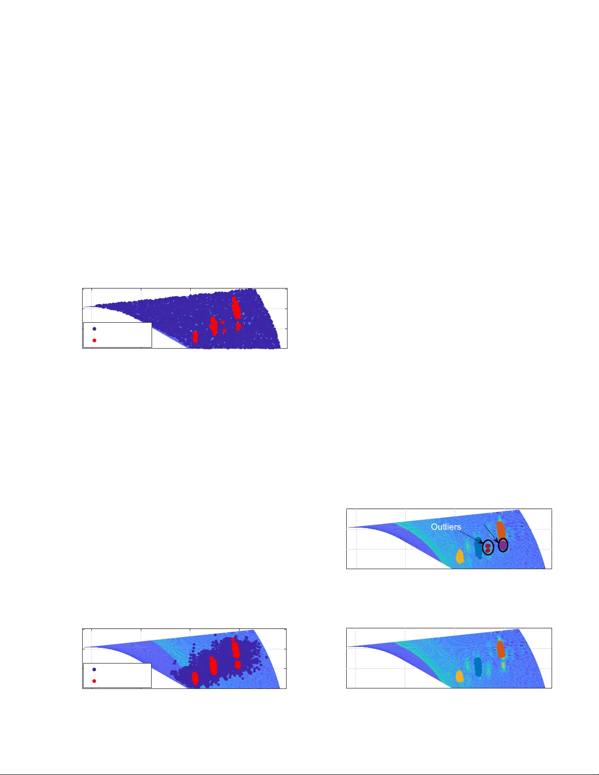
Stairs Detection for Enhancing Wheelchair Capabilities Based on Radar Sensors Sherif Abdulatif ∗ , Bernhard Kleiner ∗ , Fady Aziz ∗ , Christopher Riehs ∗ , Rory Cooper † , Urs Schneider ∗ ∗ Department of Biomechatronic System, Fraunhofer Institute for Manufacturing Engineering and Automation IP A † Human Engineering Research Laboratories, Univ ersity of Pittsbur g Email: { sherif.abdulatif, bernhard.kleiner , fady .aziz, christopher .riehs, urs.schneider } @ipa.fraunhofer .de \ rcooper@pitt.edu Abstract —Power ed wheelchair users encounter barriers to their mobility everyday . Entering a building with non barrier -free areas can massively impact a persons mobility related activities. There are a few commercial devices and some experimental that can climb stairs using for instance adaptive wheels with joints or caterpillar drive. These systems rely on the use for sensing and control. For safe automated obstacle crossing, a robust and en vironment inv ariant detection of the surrounding is necessary . Radar may prov e to be a suitable sensor for its capability to handle harsh outdoor en vironmental conditions. In this paper , we introduce a mirror based two dimensional Frequency-Modulated Continuous-W ave (FMCW) radar scanner for stair detection. A radar image based stair dimensioning approach is presented and tested under laboratory and realistic conditions. I . I N T RO D U C T I O N Mobility is a key factor in determining autonomy and independence for people with sev ere disabilities (PsD). Elec- tric powered wheelchairs (EPW) are an important means of providing mobility to PsD across the age span. Tips and falls are the most frequent reason that PsD who use EPW report to emergency rooms [1]. There is a need for more capable EPW that can reduce the risk of tips/falls or loss of control, which occur in 30%-65% of users each year [2]. T ips and falls related to EPW crashes hav e a significant effect on PsD. Improvements hav e been shown in EPWs in the past 20 years [3], [4], including reliability , better suspension to minimize vibration exposure and expanded user interfaces. Despite some improvements, current EPW design limits most users to dri ve in indoor en vironments and outdoors with mostly flat barrier-free en vironments. Furthermore, PsD using EPW hav e difficulties and thus often av oid, dri ving over unev en terrain or ov ercoming architectural barriers such as curbs and terrains non-compliant to accessibility standards [5]. Many studies were done to allow either manual or powered wheelchairs to climb the stairs. One solution introduced for stair climbing problem is installing tracks to wheelchairs [6]. Such approach needs no prior knowledge about the stairs, but irregular stair edges can easily cause slipping since all weight of the wheelchair rests on the stair edges. Another safer edge independent solution is leg-based wheelchairs to climb stairs as step by step or ev en in a high single step according to the legs elev ation capability [7]. For this approach a prior knowledge about stairs dimensions such as depth and height is crucial for safety . In [8], [9], a LID AR and camera based more general surrounding detection techniques were used to identify objects for autonomous driving wheelchairs. Howe ver , both sensors suf fer many limitations due to different lighting, surface material and harsh outdoor environmental conditions. I I . S TAI R D E T E C T I O N S E T U P A. FMCW -Radar Radar is introduced in this paper as an efficient tool for stair detection for its capability to handle outdoor measurement conditions like sun light, dust and unstructured terrain. The radar used in this paper is a compact 94 GHz FMCW radar with adjustable parameters and an aperture of about 11 ◦ [10]. The used signal modulation on the FMCW radar is a continuous sequence of chirps and each chirp is defined as a linear increasing frequency signal over time. As shown in Fig. 1, the receiv ed echo signal will have a frequency shift ( f D ) corresponding to the velocity information and a time shift ( ∆ t ) corresponding to the range information. The main adjustable parameters on the modulation related to our application are the range resolution and the maximum detectable range. The range resolution ( r res ) is defined as the minimum distance between targets where the radar is still able to distinguish them as multiple targets. Based on Eq. 1, the range resolution is only a function of the radar bandwidth ( B ) and is set to 1.5 cm (lo wer than the minimum possible distance between two consecutive steps) based on a bandwidth of 10 GHz. The maximum range ( r max ) is defined as the maximum distance from the radar where a target is still detected. From Eq. 2, the maximum range is just the range resolution relation scaled with the number of samples per chirp ( N s ). Giv en the bandwidth is set to 10 GHz, then N s is set to 200 samples per chirp to get a maximum range of 3 m which is suitable for our application. r res = c 2 B (1) r max = cN s 2 B (2) Frequency T ime f t T ransmitted Signal Received Signal f D Fig. 1: FMCW Radar transmitted and receiv ed chirps. T o extract the range information of the targets in the radar scene, a Fast Fourier T ransform (FFT) is applied to each ramp in the down conv erted receiv ed signal. Accordingly , the frequency spectrum will ha ve a strong DC component that can be eliminated by a high pass filter . In addition to peaks at frequency shifts corresponding to the time delays ( ∆ t ). As shown in Fig. 2, the frequency of each peak represents a range of a certain target and the power is correlated with the Radar Cross Section (RCS) of the corresponding target. This RCS is strongly affected by the angle of radar beam incidence, the size, the material and the shape of the target [11]. T argets with sharp edges are known to show significant high power reflections, thus radar is a con venient sensor for stairs detection and dimensioning. 0.5 1 1.5 2 2.5 Range [m] -60 -40 -20 Power [dB] DC Component Targets Fig. 2: Range profiles with peaks at the corresponding targets. B. Rotating Mirr or Based Scanner A Single Input Single Output (SISO) radar with one trans- mitting and receiving antenna can only detect range of objects within its beam aperture without angular information. Thus, to get a precise scanning of the scene, a right aperture radar is needed with an angular resolution capability . Scanning is done based on a mechanical motion of the radar and acquiring range profiles at each point, then mapping range data to correct radar positions. Different scanning techniques are often used as applying a translational motion to the radar over the height- dimension or rotating the radar over the depth plane [12]. These scanning technique are rather simple solutions, but not compact enough for wheelchair application. In this paper , we introduce a compact solution for scanning by keeping both the radar height and orientation constant and rotating the radar beam only based on a rotating mirror . The designed mirror is concav e and the surface is made from aluminum such that at any instant the radar beam is reflected by 90 ◦ to allo w scanning in the sagittal plane (height and depth) as shown in Fig. 3. The center of the mirror is horizontally aligned with the radar lens and placed at a distance of 22 cm. The rotating scanner structure is placed horizontally at a suitable wheelchair height of 40 cm. The mirror is designed with a 5 ◦ aperture and this reduction from the original radar beam aperture (11 ◦ ) will increase the vertical resolution capability . The mirror is mounted to a small shaft and can be freely mo ved ov er 340 ◦ angular range. The mirror rotation is controlled by a step motor such that at each measurement instant the mirror is static. In our setup shown in Fig. 3, the mirror is rotated by an an- gular resolution of θ res for each range spectrum measurement. This angular resolution strongly affects the height resolution (the translational distance mov ed in the height plane based on this angular rotation). Based on Eq. 3, the height resolution ( h res ) at a distance ( d ) is directly proportional with the angular resolution ( θ res ). Considering a stair detected at the chosen radar maximum range of 3 m, an angular resolution ( θ res ) of 0.25 ◦ is chosen to satisfy a height resolution ( h res ) of 1 cm which is enough for our application. h res = d tan θ res (3) Based on experiments on different staircases, the angular dynamic range is chosen from -20 ◦ abov e the horizontal depth plane to 50 ◦ below the horizontal depth plane. W ithin the specified angular range, each range spectrum is mapped to a world coordinate system. Finally , a 2D intensity map in the sagittal plane is generated representing reflected signals from different objects as shown in Fig. 4. At a distance of 1 m three steps are detected on a wooden stair as three vertical high intensity planes at different heights and depths. Height Depth Fig. 3: 2D scanner (left) and the experimental setup (right). 0 0.5 1 1.5 Distance [m] 0 0.2 0.4 0.6 Height [m] Fig. 4: 2D Radar scanned image of a 3 steps staircase. I I I . S TAI R D E T E C T I O N A L G O R I T H M In this part, we present a particle filter based plain detection algorithm to identify high intensity parts in the staircase scanned image shown in Fig. 4. The idea behind the particle filter is to represent a probability distribution function (pdf) based on random samples with corresponding weights. Thus multiple objects will be represented as a pdf. The algorithm will work by initializing particles all over the image and apply- ing iterative resampling to initialized particles till the particles con ver ge to high power areas in the intensity map. Based on the resampled particles distribution, clustering is applied to separate detected stairs. Furthermore, particles distribution in each cluster will be used to estimate height and depth of each detected stair . A. P articles Initialization and Resampling First part of the plain detection algorithm will be the particle filter initialization phase. In this phase N particles are initialized with a pre-defined distribution. As shown in Fig. 5, each particle s i (blue point) is represented as: s i = ( x i , y i , p i ) (4) where x i , y i represents the position of the i th particle (distance, height) in the sagittal plane, p i represents the po wer at this particular position and i represents the particle index from 1 to N . After initialization, all the powers are normalized to weights and each particle will get a weight w i such that the sum of all weights ( P N i =1 w i ) is equal to 1. In the second phase, resampling by replacement based on the weights w i is applied to the initial state particles distribution. During resampling, particles with high weights are more likely to be selected multiple times and replace particles with low weights [13]. Resampling is repeated recursively for multiple amount of times to insure conv ergence to high intensity plains (red points) as shown in Fig. 5. Particles distrib ution during the initialization phase can strongly affect how fast particles can conv erge to the high in- tensity areas during resampling phase. One common approach for particles initialization is to uniformly distribute all particles ov er areas with defined power v alues in the image as shown in Fig. 5. This approach is rather simple, but it can take about 15 iterations to con ver ge to the correct high intensities. 0 0.5 1 1.5 Distance [m] 0 0.2 0.4 0.6 Height [m] Initial Resampled Fig. 5: Uniform particles distribution over scanned image. In this paper , we use a Gaussian Multi-Modal (GMM) distribution initialization technique where M high intensity locations are randomly chosen within the image. A subset N / M (mode) of the particles is then initialized with a suitable variance and a mean equal to the corresponding high intensity position. The same approach is applied till we initialize all required N particles as shown in Fig. 6. After initialization, weight normalization and resampling is applied to each subset alone which will allow faster con ver gence to high intensity planes [14]. Furthermore, this distributed weight normalization and resampling approach will insure con vergence to all high intensities in the scan e ven if some areas are lower in power than others. The used multi-modal Gaussian initialization was tested on different staircase scans and it can conv erge to high intensity areas within 5 resampling iterations. For the sake of lowering the comple xity , number of particles N is chosen to be 1000 particles and number of modes M as 10 modes. Finally , to reduce the overall complexity before applying clustering to the resampled particles, redundant particles with the same exact positions and powers due to resampling with replacement are remov ed. 0 0.5 1 1.5 Distance [m] 0 0.2 0.4 0.6 Height [m] Initial Resampled Fig. 6: GMM particles distributions over scanned image. B. Clustering and Rejection In order to separate the steps detected in an image, cluster- ing is applied to the resampled particles based on their ( x, y ) positions and corresponding po wer intensities. Accordingly , cluster bounds are generated based on an adaptable sensiti vity parameter ( ρ ) to assign each particle to a cluster . The clustering sensitivity ρ can have values between 0 and 1. Increasing the sensitivity will result in more bounds and separations, thus more detected clusters. In the proposed setup, the sensitivity parameter ρ was tunned over different scans and is finally set as 0.5 to insure fair clustering. As shown in Fig. 7, fair clustering can result sometimes in erroneous clusters that can be redundant (belonging to same object) or outliers clusters. Outlier clusters are mostly scattered particles which did not con verge to high intensity area. Such scatters are known to hav e a low number of particles which can be identified and removed. A threshold on the number of particles in each cluster is introduced to identify if a cluster is an outlier . In our case, a rather simple threshold based on 10% of the mean number of particles in all clusters is used. A cluster with particles not satisfying such threshold will be remov ed from the detected clusters. T o insure uniform distribution of particles in each cluster , an outliers detection and remov al is applied to particles in each cluster . Moreov er , redundant clusters which belong to the same object must be either fused or the cluster with lo wer number of particles is rejected as marked in Fig. 7. Since a staircase is known to be detected, multiple clusters sharing relatively close position information in either depth or height are identified as redundant. A distance threshold of 10 cm is chosen to identify if multiple clusters are redundant, then the cluster with the lower relati ve position is rejected to get the final detected clusters as shown in Fig. 8. Finally , the detected number clusters after rejection corre- sponds to the number of stairs the wheelchair can climb. The particles distribution in each cluster will be used for the sake of dimensioning. In the next part, implemented enhancements to our stair detection algorithm is presented in terms of faster particles con ver gence and adding more possible use cases. 0 0.5 1 1.5 Distance [m] 0 0.2 0.4 0.6 Height [m] Redundant Fig. 7: Clustered particles ov er scanned image. 0 0.5 1 1.5 Distance [m] 0 0.2 0.4 0.6 Height [m] Step 2 Step 3 Step 1 Fig. 8: Final detected clustered particles ov er scanned image. C. Clutter F iltering During the radar scan and especially at long distances as the beam area is wider, it is likely to get reflections from unwanted objects often referred to as clutter . Due to the variability of the mixed clutter and noise, an adaptive thresholding technique for suppressing spectrum noise and keeping wanted target peaks only is needed. Constant False Alarm Rate (CF AR) is a widely used adaptiv e thresholding method in radar systems to separate target peaks from neighbor noise. CF AR detection is based on gain control to preserv e a constant rate of f alse target detections in the case of varying clutter and noise lev els. There are dif ferent techniques for applying CF AR in the radar reception to pre vent high false alarm rates in the presence of interference such as jamming or clutter residue. In this paper , Cell-A veraging (CA-) CF AR [15] is applied for its sim- plicity . In CA-CF AR, a sliding window over the range profile is used to compute the average power within the window cells. The sliding window averaging considers a potential peak to be in the middle, thus the average is computed without considering the middle cells. As shown in Fig. 9, the required target peaks exceed the CF AR threshold and otherwise is considered as noise. T o insure presence of target stairs only in radar scans, any range power below the CF AR threshold is assigned a value equal to the minimum receiv ed power and v alues exceeding the threshold are taken as it is. After coordinate correction at each mirror rotation, a 2D CF AR intensity map in sagittal plane can be produced. As shown in Fig. 10, the high intensity peaks representing stairs are clearly seen as high yellow values. On the other hand, noise and clutter can be identified as complete blue background. The CF AR technique was tested on different stair cases and it shows clear improv ement in clutter and noise rejection. Moreover , this CF AR technique has a major influence in the particle filter complexity as particles can con ver ge much faster to high intensity areas. As mentioned abov e the stair detection particle filter algorithm can take up to 5 iterations to conv erge to correct steps. CF AR technique was tested on several measurements and the particles can conv erge during resampling within 2 iterations only . 0 0.5 1 1.5 2 2.5 Range [m] -60 -40 -20 0 Power [dB] Range Spectrum CFAR Spectrum Fig. 9: CF AR threshold ov er detected range profiles. 0 0.5 1 1.5 Distance [m] 0 0.2 0.4 0.6 Height [m] Fig. 10: 2D Radar scanned CF AR image of a 3 steps staircase. I V . S TA I R S D I M E N S I O N I N G After applying our proposed particle filter based stair detec- tion algorithm and clutter filtering, now particles are correctly distributed over each step and can be used for dimensioning. For successful stair climbing, the number of stairs to climb represented as the number of detected clusters, depth and height of each step is needed. Depth can be estimated by first subtracting the distance between the radar and the mirror (22 cm) mention in Section II from all the range measurements. Now the radar can be considered at 0 position and the distance between the radar and each step can be estimated based on particles distribution in the x -plane. This can be achieved by computing the weighted av erage of particles position ov er the x -plane in each cluster . Giv en number of particles in the i th cluster is N i and each particle depth position as x j and weight as w j , where index j v ary from 1 to N i . Then all the particles weights are normalized to 1 in each cluster and the depth of this cluster ( d i ) can be estimated as: d i = N i X 1 w j .x j (5) Height can be estimated based on first step appearance in the height plane. In comparison to laser, the origin of reflection with the experimental setup can only be measured directly with an uncertainty of 1.8 cm in y -Position at a range of 2 m. T o overcome this limitation we introduce the usage of a 3 dB beam model of the radar unit. As sho wn in Fig. 11, the aperture is defined as the angle between upper and lower 3 dB ranges and in our method the height error is estimated as distance from beam center and the lo wer 3 dB beam (half aperture). Accordingly , the correct height can be estimated by getting the position of the top particle in each cluster . Then the height error subtracted from the top particle y -position is computed based on Eq. 3 where distance is considered as depth d i and θ res as half the mirror aperture (2.5 ◦ ). Fig. 11: Height estimation using a 3 dB beam model V . R E S U LT S The introduced scanner was then placed o ver a mobile surface and was used to scan several staircases. In this part, scans of staircases with the same number of steps (3 steps) is used for fair comparison. As shown in Fig. 12, Stair A is a wooden constructed staircase for initial tests and Stair B was used to test dark ceramic material reflections. Finally , Stair C was used to test the algorithm detection capability of floating steps. The scanner was used to collect the scans ov er these staircases with the same initial position (0.5 m) and height (0.4 m). The particle filter was then used for steps detection and dimensioning, then the stairs are reconstructed and compared to real dimensions as sho wn in Fig. 13. The errors of both depth and height estimations of mentioned staircases are shown in T able I and detected steps are ordered in ascending depth. The depth estimation in all cases is always less than 0.5 cm and height estimation is a bit worth as it is additionally influenced by the mechanical model and aperture correction. Moreover , the height error scales with the depth as explained in Eq. 3. T able I: Distance errors over tested staircases. Stairs/ Accuracy Depth [cm] Height [cm] Step 1 Step 2 Step 3 Step 1 Step 2 Step 3 Stair A 0.2 0.4 0.3 0.5 0.7 1 Stair B 0.1 0.3 0.5 0.3 1 1.2 Stair C 0.2 0.1 0.4 0.6 0.6 1.5 (a) Stair A (b) Stair B (c) Stair C Fig. 12: Different stair types used for testing. 0 0.5 1 1.5 Distance [m] 0 0.2 0.4 0.6 Height [m] Real Stair Reconstructed Stair Fig. 13: Reconstructed staircase against real dimensions. V I . C O N C L U S I O N A N D F U RT H E R S C E N A R I O S In this paper we introduced a mirror based stair scanner for wheelchair stair climbing applications. Moreover , we in- troduced a detection and dimensioning technique based on particle filter . The scanner was tested and showed good results for the desired application. W e mainly addressed the scenario of a wheelchair user climbing a staircase (up stair detection), thus the radar scanner was used to scan over the depth plane to identify and dimension steps in the staircase. One other possible scenario that will yield similar results will be to apply our radar scanner in the application of downstairs detection. In this case, the radar scanner will work by scanning ov er the height plane as shown in Fig. 14. This scenario is particularly achiev able due to the introduced compact rotating mirror scanner . This proposed structure can provide the wheelchair user with additional capabilities of scanning in different plane directions. This can be achiev ed by mounting the structure to a movable pole which can move the scanner over the required staircase. Depth Height Fig. 14: Scanner illustration for downstairs detection scenario. R E F E R E N C E S [1] W .-Y . Chen, Y . Jang, J.-D. W ang, W .-N. Huang, C.-C. Chang, H.- F . Mao, and Y .-H. W ang, “Wheelchair-related accidents: relationship with wheelchair-using behavior in active community wheelchair users, ” Ar chives of physical medicine and rehabilitation , vol. 92, no. 6, pp. 892–898, 2011. [2] H. Xiang, A. Chany , and G. A. Smith, “Wheelchair related injuries treated in us emergency departments, ” Injury pre vention , vol. 12, no. 1, pp. 8–11, 2006. [3] D. Ding and R. A. Cooper , “Electric powered wheelchairs, ” IEEE Contr ol Systems , vol. 25, no. 2, pp. 22–34, 2005. [4] H. W ang, H.-Y . Liu, J. Pearlman, R. Cooper, A. Jefferds, S. Connor , and R. A. Cooper, “Relationship between wheelchair durability and wheelchair type and years of test, ” Disability and Rehabilitation: Assistive T echnology , vol. 5, no. 5, pp. 318–322, 2010. [5] USA Access Board, “ Americans with disabilities act and architectural barriers act accessibility guidelines, ” 2004. [6] T . Chair , http://www .topchair.net, 2015. [7] J. Candiotti, S. A. Sundaram, B. Daveler , B. Gebrosky , G. Grindle, H. W ang, and R. A. Cooper , “Kinematics and stability analysis of a novel power wheelchair when traversing architectural barriers, ” T opics in Spinal Cord Injury Rehabilitation , vol. 23, no. 2, pp. 110–119, 2017. [8] H. Grewal, A. Matthews, R. T ea, and K. George, “Lidar-based au- tonomous wheelchair , ” in Sensors Applications Symposium (SAS) . IEEE, 2017, pp. 1–6. [9] T . H. Nguyen, J. S. Nguyen, D. M. Pham, and H. T . Nguyen, “Real-time obstacle detection for an autonomous wheelchair using stereoscopic cameras, ” in Engineering in Medicine and Biology Society , 29th Annual International Conference . IEEE, 2007, pp. 4775–4778. [10] C. Zech, A. H ¨ ulsmann, M. Schlechtweg, S. Reinold, C. Giers, B. Kleiner , L. Georgi, R. Kahle, K.-F . Becker , and O. Ambacher, “ A compact w-band lfmcw radar module with high accuracy and integrated signal processing, ” in Eur opean Micr owave Conference (EuMC) . IEEE, 2015, pp. 554–557. [11] E. F . Knott, Radar cr oss section measurements . Springer Science & Business Media, 2012. [12] J. P . Fitch, Synthetic aperture radar . Springer Science & Business Media, 2012. [13] B. Efron and R. J. Tibshirani, An intr oduction to the bootstrap . CRC press, 1994. [14] L. M. Murray , A. Lee, and P . E. Jacob, “Parallel resampling in the particle filter , ” Journal of Computational and Graphical Statistics , vol. 25, no. 3, pp. 789–805, 2016. [15] M. A. Richards, Fundamentals of radar signal processing . T ata McGraw-Hill Education, 2005.
Original Paper
Loading high-quality paper...
Comments & Academic Discussion
Loading comments...
Leave a Comment