A Distributed Dynamic Programming-based Solution for Load Management in Smart Grids
Load management is being recognized as an important option for active user participation in the energy market. Traditional load management methods usually require a centralized powerful control center and a two-way communication network between the s…
Authors: Wei Zhang, Yinliang Xu, Sisi Li
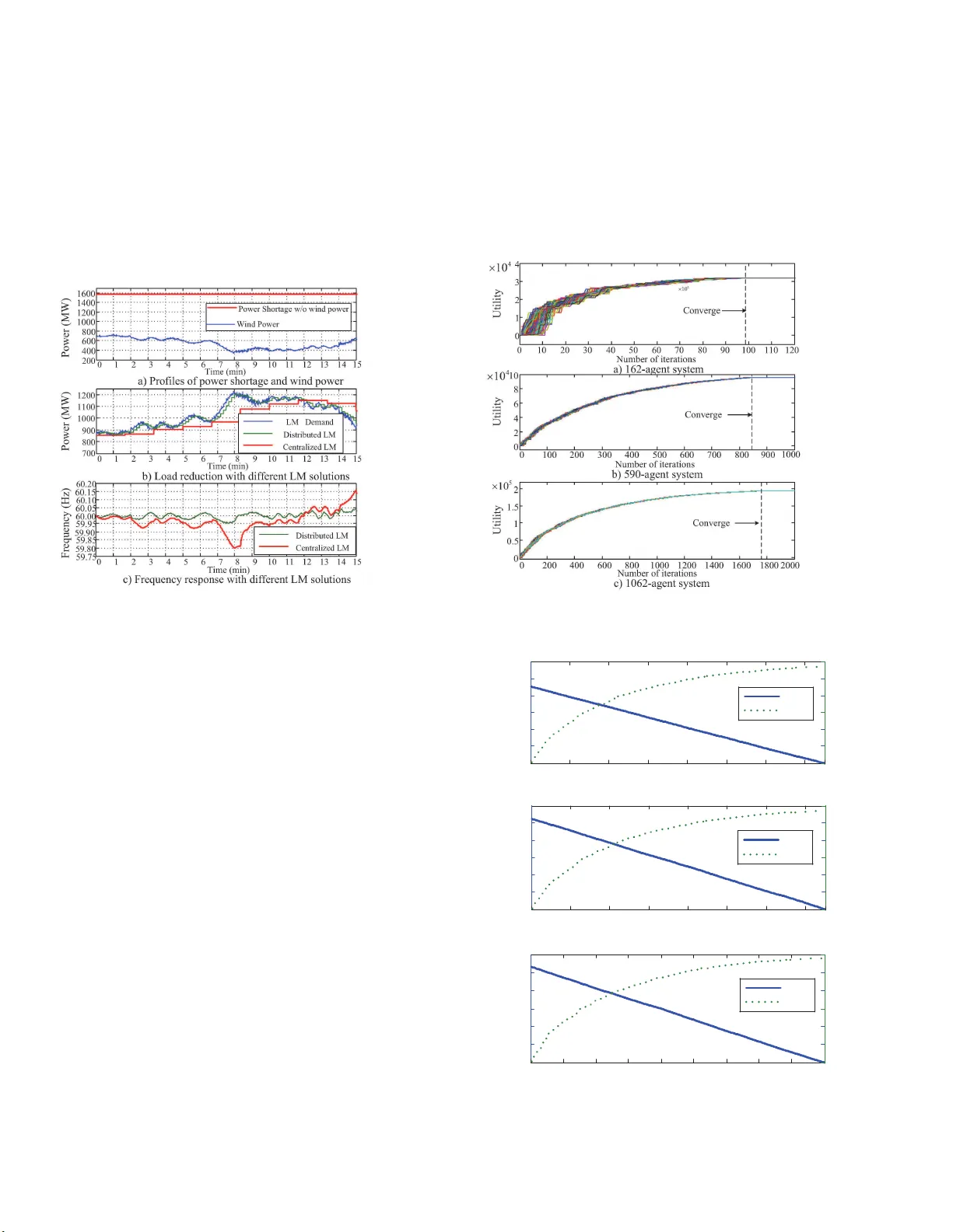
1 A Distrib uted Dynamic Programming-based Solution for Load Manageme nt in Smart Grids W ei Zhang, Member , IEEE , Y inliang Xu, Membe r , IEEE , Sisi Li, Member , IEEE , MengChu Zhou, F ellow , IEEE , W enxin Liu, Senior Member , IEEE , Y ing Xu , Member , IEEE Abstract —Load management is being reco gnized as an important option for active user p articipation in the energy market. T raditional load management methods usually require a centralized powerful control center and a two-way communication network between the system operator s and energy end-users. The increasing user participation in smart grids may limit their applications. In this paper , a distributed solution for loa d management in emerging smart grids is p roposed. The load management problem is fo rmulated as a constrained optimization pr obl em aiming at max imizing th e ove rall utility of users while meeting the requirement for load r ed uction requested by the system operator , and is solved by using a distributed dynamic progra mming algorithm. Th e algorithm is implemented via a distributed framew ork and th us can deliv er a high ly desired distributed solution. It av oids the required use of a ce ntralized coordinator or contro l center , and can achiev e satisfactory outcomes fo r load management. Simulation results with various test systems demonstrate its effec tiveness. Index T erms —Load Management, Di stributed Algorithm, Dy- namic Pro gramming, Smart Grids I . I N T RO D U C T I O N Driv en b y economic a nd en vir o nmental concer ns, the power grid is d emanding f or transform ation to an efficient, flexible, reliable and sustainable energy grid [1], [2]. This is the frequently mentioned ‘smart grid’. First, a smart grid is expected to ac- commod ate m ore and more renewable energy sourc e s. Second, it need s to ac cept more and mo re active p articipation fro m energy end- u sers. This user particip ation can actively improve the e lec tricity market b y redu cing the overall cost o f en e rgy supply , increasing th e reserve margin, and assisting to ma intain the system reliability [3]. In recent years, load ma nagement ( L M) pro gram, also known as demand response (DR), is introduce d as on e of imp ressi ve options This work is supported by Nationa l Natural Science Foundat ion of China under Grant 51507037. W . Zhang is with Department of Elect rical Engineeri ng, Harbin Institu te of T echnol ogy , Harbin 150001, China (e-mail: wzp s@hit.edu.cn). Y . Xu is with Sun Y at-sen Uni versity-Carne gie Mellon Uni versit y Joint Insti- tute of Engin eering, Sun Y at-Sen Univ ersity , Guangzhou 510275, Chin a(e-mail : xuylian g@mail.sysu.edu.cn). S. Li is with the Depart ment of Electrical and Computer E ngineering, Ne w Jer- sey Institute of T echnology , New ark, NJ 07102-1982 USA(e-mail: sl98@njit.edu). M. C. Zhou is with the Departmen t of E lect rical a nd Computer Enginee ring, Ne w Jersey Institu te of T echnolog y , Ne wark, NJ 07 102-1982 USA a nd also with Departmen t of Electrica l and Co mputer Engi neering, King Abdulazi z Univ ersity , Jeddah, Sa udi Arabia (e-mail: zhou@nji t.edu). W . L iu is with Department of Electrica l and Computer Engineering, Lehigh Uni versity , Bethle hem, P A 18 015 USA (e-mail: wliu@leh igh.edu). Y . Xu is with Power Dispatch and Control Center , North China Branch of State Grid Cor poration , Beijing 100053, Chi na (e-mail: dahei xu@1 63.com) for user par ticipation. It re f ers to chan ges in electricity adjustment by end-u se custom ers in response to electricity price chan ges over time, or in respon se to the incentive payments designed to lower electricity consumption when the system capacity is stretched or reliability is jeopa r dized [4]. EPRI estimates that DR has th e potential to reduce the peak demand b y 4500 0 MW [5]. The Battle Group c la im s th a t even with simple price mechanisms, DR could provide annu al b enefits in tens of millio ns of dollars [6 ]. The U.S. Feder al En ergy Regulatory Co m mission has cond ucted a benefit-cost analysis an d sh ows that if LM is in corpora ted into the regional energy m arket, over $ 6 0 billion saving could be ach iev e d [7]. LM p rograms take tw o f o rms, in centive-based p r ograms (I BP) and price-based pr ograms (PBP) [8]. In the former, participan ts are re warded with money to reduce their electricity consumption (load) wh en requ ested b y the prog ram sp onsor, triggered by high electricity prices o r pe a k in dema n d. The earned incentives depend on bo th the amou nt of load reduc tio n req uired by the progr am spo nsor and corre sp onding ince ntiv e s o ffered during these critical periods. Many utilities or third-p arty organiza tions in Nor th America an d around the globe have experien ces with IBP . Califo rnia-based PG&E offers base interru ptible program and dem and bidding program, and both belon g to this class [9] . The e mergency DR program u sed by Pennsylvania-New Jersey- Maryland p ower m arket offers energy pa yments to custom ers who reduce their load during system e m ergency , which also belongs to IBP [10]. PBP g i ves custom ers dyna m ic pricing rates that reflect the value an d cost of electricity du ring different periods. The ultimate objective of these pro grams is to flatten the demand curve by offering h ig h price d uring peak periods and low pr ice s du ring off-peak perio ds. Th e rates used by PBP include time-o f-use rate, critical peak p ricing, extreme day p ricing, real time pricing, etc. [11]. In deregulated market, many utility comp anies are a b le to provide PBP [12]. The PBP p articipants can benefit from an LM progr am by saving electricity bills instead of receiving money paymen t from the prog ram sp onsor directly . Over the past few decades, both the m anner in which LM was app lied and the m arket kn owledge of its potential values had improved. Ho wever , th e exp e riences with LM recei ve mixed revie ws [13]. Overall, current LM p rogram s are too clumsy to some extent and inco nvenient for continu ous and repeated use. The issues such as reliability drop d ue to frequent schedule ad - justment, com munication link loss or operating con dition chang es 2 accompany the practice of LM. Prog ram participants may also experience comfort and business con tinuity concerns when they fulfill their LM targets. T o overcome these prob lems, a more activ e, auto m ated and in tegra ted LM solution is highly demand e d . Some dissenters argued th a t the owners with LM capac ity were in unrelated businesses and the grid op erator should not count on them . Howe ver, large-scale LM has proven its v alu e in e n hancing grid reliability and red ucing the overall cost o f energy sup ply . Th e rollou t of intermittent resources, such as wind and so lar , is increasing the r elev ance o f L M a s a top- tier resource [14]. T o integrate more LM resou rces into the system, the LM control system tends to become more sophisticated with parallel and mu ltichannel commun ications am ong its elements. It is well r e c ognized th at the trad itional vertical- based, centr alized command ed L M solution is insufficient for this b u rdensome task. It is kn own that cen tralized solutions are susceptible to single point failures and may not be applicable under certain situations [15]. The co ntrol center for centr a lize d an LM solution n eeds to collect all th e informatio n fr o m energy u ser s and a powerful central controller is required to pro cess a hu ge am o unt of data [16]. Consequen tly , these solutions may fail to respon d in a timely manner, especially durin g the peak-load period when the power grid is under hig h stress. Moreover , th e app lica tions of LM in industrial o r resid e ntial sectors have been limited due to the lack of k nowledge about the co ntrollability of loads [17]. In the existing LM or DR programs with such direct or interrup tible load control, the equipment of participan ts is required to h av e the ability to be remotely shut down by utilities at a short notice. For the en ergy users withou t remo te control access, they cannot be enrolled into the LM program even if they are willing to do so. Thus, these centr a lized-based LM applicatio ns cannot fully exploit the potential of LM program s. T o addre ss the afor e m entioned issues caused by centralized solutions, various distributed solutions h av e been pr oposed. In [18], a d istributed LM algorithm is proposed for a plug-in electrical vehicle charging p roblem in a smart grid b ased o n a co ngestion p rice mechan ism. However , th e algo rithm relies on obtainin g th e unified price signal in a centralized way . In [19], a distributed LM s trategy based on the alternating direc tio n method of multipliers is developed. Y et, the pr oposed method not only req uires all energy users to rep o rt their loads to the system operator but also needs th e system operator to send the control signals back to eac h user . This two-way communication mechanism the r eby r equires a co mmunication system to have hig h transmission rate since the num ber of energy users participating in an LM can be very large. The introduction of aggregators m a y relieve the burden of the system operator for com m unication to some extent. Howe ver , to r ender a reliable LM p rogram , hea vy commun ication between the system operator/ag g regator and users should be av oided. T o overcome these lim itatio ns with existing LM/DR solutions, we need to develop a active and flexible LM solution with a distributed fra mew o rk and comm u nication- efficient mechanism. This paper presents a distributed LM solutio n to redu ce peak load in smart grids. The pro posed solution aims at m aximizing Fig. 1: Design of the pro posed L M system the to tal utility of a ll en e rgy u sers whe r e the LM p r oblem is formu late d as an optimizatio n problem. A distributed dy namic progr amming (DDP) is em ployed to so lve th e pro blem in a distributed way . I n the proposed solutio n, each energy end -user is represented by a load manag ement a g ent (LMA). An LMA can exchan g e information with its neig hboring LMAs. Du ring LM, an LMA first receives the information of load settings and incentive for an L M event that is br oadcasted by the system operator . Then the LMA par ticipates in the optimization process in co operation with its neighborin g agen ts to o btain an LM solution. The o btained solution tend s to ma x imize th e total utility of e nergy users while meetin g the requiremen t for load r eduction. The rest of the p aper is organized as follows. Section I I introdu c es th e design of the p roposed LM system and formulates an L M problem. Section III presents a DDP algorith m for solving the LM pro blem an d discusses its imp lementation. Section IV presents simulation results and Section VI con c lu des the paper . I I . S Y S T E M D E S I G N A N D P RO B L E M F O R M U L AT I O N A. System description The d esigned LM system is depicted in Fig. 1. W e adopt an incentive-based mecha nism as it can be used in a regulated or deregulated energy market. Each user is assigned w ith an agent, LMA, for LM. The load of a user can be ph ysical devices or virtual “load” th at is agg r egated throu gh several physical de v ice s, such as gatew ays introduced in [20]. When an LM ev ent is initiated during a peak-lo ad period, the system o perator (u tilities) first calculates the total loads for all users af ter LM, P G , based o n the cur rent need for lo ad reduction , P R . P G is calculate a s P G = P M − P R with P M being the cu rrently ru nning load. Then th e system operato r broad casts the informa tio n o f P G and I c to each LM A. Her e I c is the incentive. Once this information is ob tained, the agen ts co operate with each other autonomou sly to achieve the LM target, witho ut a centralized controller or coordinator . Each LMA is designed to receive in formation fro m the sy stem operato r , to exchange informa tio n with its neighbor ing agents and to up d ate its load settings accord ing to certain r u les based on a DDP a lgorithm. The topolog y of the commun ication n e twork for info rmation exchan ge among these distributed agents can b e designed to be th e same as that of the po wer network. Ho wever , other topologies m ay be adopted [16]. The proposed LM solution needs com munication links among neighbo rs only . As two n eighbor s a r e usually clo se to each other, c ommunica tion in frastructure inv e stme nt is thu s small. By utilizing some particu lar com munication technology such as 3 power line communicatio n [21], this part of inv e stment can be reduced to th e minim al. These agents a c t as a coalition to m e e t the r e quiremen t for load r eduction while maximizing their overall energy-use utility by tak ing into accou nt the com fort and business continuity concerns. This problem is formulated as a constrained optimization prob lem to b e discussed in the next subsection. B. Pr oblem F ormulation It is assumed that there are n users av ailable for an LM progr am. Generally , the system op erator does n ot h av e th e right to control the loads of users, and is on ly respo nsible for broad casting informa tio n of P G and I C to all users. Th e users co operate with each other autonomou sly to m aximize their overall utility while meeting the minimum r equiremen t f or load reduction requ ested by the system operato r to reduce the peak load. Considering that a user can shed partial o r all of its lo ad, we represent the status o f a load sector by using a state v ariable x k i as: x k i = ( 1 if the k th load sector is on 0 if the k th load sector is off where i = 1 , 2 , · · · , n , k = 1 , 2 , · · · n i with n i being the numb er of the lo ad sectors of user i . F or a user with n i load sectors, the LM can co ntrol each load sector, thu s resulting 2 n i load red uction settings. Acco rdingly , a user can shed a portio n of its load by setting x k i proper ly . Let P k Li be th e k th load sector of user i befo re an LM event. According ly , the utility of user i during the LM e vent can be defined as: U i = n i X k =1 x k i W k i P k Li − I c n i X k =1 x k i P k Li (1) where W k i is a pre-defined weight f actor for user i . It should be noted that the weigh t factor can be defined based on either the priority le vel of the load, which in dicates the load preference , or the pr oduction of unit power con sumption [22]. The first right term o f (1) denotes the benefits of user i by c o nsuming a certain amount of po wer, and the seco nd ter m denotes the incen tives loss if the correspo nding lo ads are in effect. T o maximize the total utility o f all users, i.e. , the utility of the LM coalition, we have the o bjective functio n : max n X i =1 U i = n X i =1 ( n i X k =1 x k i W k i P k Li − I c n i X k =1 x k i P k Li ) (2) T o satisfy the requ irement for load redu ction given by the system opera to r , the total load of users needs to satisfy: n X i =1 n i X k =1 x k i P k Li = P G (3) Since n P i =1 I c n i P k =1 x k i P k Li = I c ∗ P G , the LM problem is f o rmu- lated as a con strained o ptimization problem as: max n P i =1 n i P k =1 x k i W k i P k Li , subject to n P i =1 n i P k =1 x k i P k Li = P G (4) The optimiz a tion p r oblem formu lated in (2)-(4) is on e of the practical LM pro grams that aims at maximizin g the overall utility of users wh ile satisfying the load reduction requirement gi ven by the system ope r ator [23]. I t c a n be sho wn th at this optimization problem is actually a 0–1 knapsack or b in-packin g prob lem, and dynamic programm ing (DP) is o n e of the effecti ve techniques to solve this kind of problems. T o r e n der an autonomo us LM solutio n, traditional m e th ods may be insufficient as they u sually demand centr alized comman d based structures. For centralized solu tio ns, th e com munication traffic and low-latency m ay n ot b e an issue if only a small number of users are par ticipating in the LM prog ram. Ho wever , when more an d m ore user s with multiple load sector s (devices) are enrolled into it, one has to consider the potential traffic jam since the commo n con trol center has to collect all the da ta. Another issue with centralized sch emes is th e con trol access o f user s’ load sectors. Gen erally , u ser s are reluctant to allo w th e system operator to contro l their d evices, which may lead to u nbearable interrup tio ns o f their electricity sup ply . The redundant centr a lize d scheme s eems to be an alternative solution, but neither user s nor utilities are willing to pay for this inves tment. Now adays, distributed intellig e nce is making h eadway in smart grid application s. By a) creating a sensor y network spread acro ss our transmission, distribution and local consumption systems and b) integrating with c o mmunicatio n ne tworks, intelligent devices, etc., the d istributed co ntrol and optimiz a tion o f the electr ic power gr id tend to d riv e the current power grid to be a more reliable, m ore secure , more en ergy-efficient “sma r t gr id ” [24]. This motiv ates us to develop a distributed algo rithm that can solve an LM problem in a distributed way , leading to a n autonomou s LM solution. I I I . D I S T R I B U T E D D Y N A M I C P RO G R A M M I N G A. Abstract F ramework of Dynamic Pr ogramming (DP) The abstract frame work for DP , first introduced in [25 ], is used to illustrate the pro posed DDP . Let S b e the set of feasible states and its elements ar e defined as state variables d enoted by vector x . Let F be the set of all extended real-valued fun ctions J : S → [ − ∞ , + ∞ ] on S . ∀ J 1 , J 2 ∈ F , the following notation is used for convenience: ( J 1 ≤ J 2 , if J 1 ( x ) ≤ J 2 ( x ) ∀ x ∈ S J 1 = J 2 , if J 1 ( x ) = J 2 ( x ) ∀ x ∈ S (5) Let H : S × F → [ −∞ , + ∞ ] b e the mappin g which is monoto ne in the sense that for all x ∈ S , H ( x , J 1 ) ≤ H ( x , J 2 ) , ∀ J 1 , J 2 ∈ F with J 1 ≤ J 2 (6) The DP objective is to find a function J ⋆ ∈ F such that J ⋆ ( x ) = inf x ∈ S H ( x , J ⋆ ) , ∀ x ∈ S (7) Define the mappin g T : F → F as: T ( J )( x ) = inf x ∈ S H ( x , J ) (8) Here, T () is a serial of o peration or co mputation pr ocedures, collectively d efined as the oper ator to ma p the objecti ve functio n to its optimu m . Accordingly , the problem can be stated as to fin d the fixed point of T within F [26], such that: J ⋆ = T ( J ⋆ ) (9) 4 For th e L M problem gi ven in (4), to max imize overall u tility of n users und er the c ondition that the total generation is less than P G , the DP pro cess can be described as: f ⋆ k = mi n { f ⋆ k − 1 − x k W k P Lk } , f ⋆ 0 = 0 , subject to P i =1 x i W i P Li ≤ P G (10) where x k is the k th element of x , and k = 1 , 2 , · · · , n . Define H and J as follows: H ( x k , J ⋆ ) = J ⋆ ( x 1 , ...x k − 1 ) − x k W k P Lk (11a) J ⋆ ( x 1 , x 2 , ...x k − 1 ) = f ⋆ k − 1 (11b) Thus, the mapping T is then defined as: T ( J )( x 1 , · · · , x k ) = inf x ∈ S H ( x k , J ⋆ ) (12) From th e definition g i ven above, on e can see that the LM problem can be g eneralized as a DP p roblem. It is w orthy to p o int out that the or iginal u tility maximization p roblem gi ven in (4) is translated to a minimization problem as shown in ( 10). Notice that H d efined in (11a) is monoto ne since J is nondecrea sin g and x k , W k and P Lk are non negati ve. B. Distrib uted So lution for Dynamic Pr ogramming P r oblem For an LM problem , it is assumed that e a ch loa d /user is assigned with an ag ent fo r distributed co mputation. For a system with n agents, the state space S is composed of n st ate variables, x 1 , x 2 , · · · , and x n . Each agent is respon sible fo r com puting the values of the solution fu nction J ⋆ at x i . Age n t j is said to be a neighbo r of agent i if j 6 = i and there exists a co mmunicatio n link between i and j . The set of all neighbors of i is denoted as N ( i ) . Intuiti vely , j is n ot a neighbor of i if the values of J on x j do not influence the values of T ( J ) on x i . As a result, in ord er to compute T ( J ) on x i , age nt i n eeds to k now only the values of J on x j , j ∈ N ( i ) and, possibly , on x i . The op tim al LM solution is obtained via the cooperation of all agents thro ugh a two-stage procedure, i.e., in formation discovery stage and state update stage. Each agen t i has two buffers p e r neighbo r j ∈ N ( i ) d e n oted as J ij and x ij respectively . J ij stores the latest estimates o f solution function J ⋆ , from agen t j and x ij stores the states corr esponding to J ij . In ad dition, ag e nt i has b u ffers J ii and x ii , which are used to store its own estimates of the solution func tio n J ⋆ and corre- sponding states. At each iteratio n, it first com municates with its neighbo ring agents ( j, j ∈ N ( i ) ) to obtain the irs latest estimates on the op timal solution an d state variables during infor mation discovery stag e. Then it computes its ne w estimate on the optimal solution ( J ⋆ ) and states ( x ) at the state u pdate stage. The update rules for the DDP algo rithm can be summarized as follows: Stage 1 Infor mation discov ery(ID): ( J ij [ t + 1] = J j j [ t ] x ij [ t + 1] = x j j [ t ] (13) Stage 2 State update ( SU): J ii [ t + 1] = inf x i ∈ S H ( J ii [ t ] , J ij [ t + 1] , x i ) x ii [ t + 1] = ar g { inf x ∈ S H ( J ii [ t ] , J ij [ t + 1] , x i ) } (14) According to [26], the converged v alues of J ⋆ and x ⋆ can be written as: lim t →∞ J ij [ t ] = J ii [ t ] = J ⋆ lim t →∞ x ij [ t ] = x ii [ t ] = x ⋆ (15) The condition s f or con vergence are as follows: 1) The r e exists a positive scalar P such that, for e very agent i , ev ery P steps of iteration contains at least one info rmation exchange stage for agent i to communicate with its neigh- boring agents and at least one state u pdate stage f o r agent i [26]; and 2) The r e exist two fun ctions J and J such that the set of all function s J ∈ F with J ≤ J ≤ J b elongs to F , and J ≥ T ( J ) , T ( J ) ≥ J (16) and, lim t →∞ T t ( J )( x ) = J ⋆ ( x ) (17a) lim t →∞ T t ( J )( x ) = J ⋆ ( x ) (17b) The first co ndition indicates tha t, both info rmation exchange and state update stages are necessary for the conver gence. How- ev er , no o th er re q uirements ar e impo sed on the timing, seq uence of the two iteration stag es. Accordin g ly , the state update stage can be co nducted after the e xecu tio n of serval information exchang es, and vice versa. T h us, the a lg orithm can be easily implemented by using an asyn chrono us commun ication protocol. The second condition guarantee s the existence of a fixed poin t for the LP problem [ 27]. As can be seen that, agen ts exchan ge data with their neighbo rs only at Stage 1 during the optimization. The me ssage transmitted includes two par ts, namely the head er informa tio n and the op timization data. T he first one con tains the inf ormation of agent ID, iteration n u mber, which is 32- bit data and the latter is determined by th e dimension of the state variables. J ij is a scalar number an d x ij is an n-dimension al vector , with n bein g th e number of the load sectors. According ly , the size o f the exchanged is d ata 32 + ( n + 1) × 2 (assume d ouble-ty pe data is used to store the optimization data) .As can be seen that, the volume of data is linearly proportio nal to th e size of the system, hen ce can scale well with the system size. The com plexity of the proposed DDP is determined by the number of iterations req uired for ea ch agent to reach its optimu m. The LM prob lem for mulated in (4) is actu al a 0 − 1 k napsack problem which can also be translated to a sh ortest path problem [28]. Acco rding to Dijkstra’ s d y namic p r ogramm in g algo rithm [28], [29 ] , its compu ta tio n com p lexity is O ( n ) for centralized im- plementation , with n being th e num b er of the n odes (load sector s). Howe ver, fo r distributed imp lementation, the computation efforts are distributed to each node, thus the co mputation complexity is scaled down by a factor of n . During optimiz a tio n, each agent commun icates with its ne ig hbors accord ing to (13) (Stag e 1) and then u pdates its state accordin g to (14) (Stage 2). Le t n e max denote 5 the maximum number of neighbo rs an agent can hav e , then the maximum computation needs for these two stages are bound ed by n e max , corresponding to the computation com p lexity of O (1) . Thereby , the computatio n complexity of th e pr oposed DDP is O ( n ) instead of O ( n 2 ) . Theoretically , one can find the solution f u nctions that satisfy (16). Howev er , in pr actice, it is hard to provide off-the-shell formu lae f or them . Y et, the DDP can still converge to a fixed poin t that is at least locally optimal solution since the LP prob lem is a non-co n vex o ptimization problem . As a r esult, the DDP algo rithm realizes fast and distributed calculation withou t g uaranteeing its solution’ s glo bal optimality . In this p aper , we define a perfor- mance index to e valuate th e proposed DDP algorithm as: I p = f ⋆ d f ⋆ g × t g t d (18) Here, f ⋆ d and f ⋆ c are the ob jectiv e fu n ction v alues obtained by the DDP and global centr alized algorith m, respectively , and t d and t c are co rrespond ing time consumed by th ese two alg orithms. Large I p signifies the h igh per f ormance of the algorithm. In the simulation p art, we will in vestigate the systems with different sizes to ev alua te the performance of DDP . During an LM ev e n t, once the agent co rrespond ing to a user receives the inform ation of incentiv e and total lo ad ( I c and P G ), it first initializes its states with the fea sible load settings, then exchang es th e infor mation of th e latest states and solution function values with its neighb oring age nts, which correspo nds to the 1 st stage update rule for DPP g i ven in (13). At the 2 nd stage, the agent decides the current states o f agents loca lly based on the up-to-d ate inf o rmation obtained from stag e 1, as giv en in (14). These two stages of in formation excha n ge and state update are repeated by the agent until convergence. During each step of itera tio n, an agent is only r esponsible for excha nging inform ation with its com munication neigh bors and updating its o wn states. The proposed LM solution actually distributes the com putation amo n g multiple age nts. It n either requires a powerful centr a l contr oller to process a huge a m ount of data nor a sophisticated commun ication network. In addition , the distributed solu tion is fle xible and able to automatically ad a pt to chang es o f operating condition s, to be demonstrated later . C. Numerical Example For a simple system with three u sers, the to tal load reduction required by the system op erator is 30 MW for on e hour, and incentive is set to $0.50/k Wh for qualifying load reduction. The load baseline of the ag gregator is set to 9 0 MW . Th en, the to ta l load settin g of the u sers a g gregated by the agg regator for L M is 60 MW . Assume load baselines fo r user s # 1, #2 and #3 are 20, 30(10,20 ) a nd 40 MW an d weights of users are 2, 3, and 4, respectively . Here, user # 2 has two load le vels with load of 10 MW and 20 MW respectively . The com m unication n etwork topolog y f or L MAs of users is shown in Fig. 2. Agen ts # 1 and #3 can c o mmunicate agent #2 only , while a g ent # 2 can communicate Ag e nt1 Ag e nt2 Ag e nt3 Fig. 2: T opology of comm unication ne twork for agents T able I: Initialization of agents Agent States( x ii \ x ij ) Utility( J ii \ J ij ) 1 x 11 x 12 − J 11 J 12 − [1 , (0 0) , 0] [1 , (0 0) , 0] − 40 40 − 2 x 21 x 22 x 23 J 21 J 22 J 23 [0 , (1 1) , 0] [0 , (1 1) , 0] [0 , (1 1) , 0] 90 90 90 3 − x 32 x 33 − J 32 J 33 − [0 , (0 0) , 1] [0 , (0 0) , 1] − 160 160 with both of them. Th erefore, agen ts # 1’ s on ly neighbo r is agent #2, agent #3’ s o n ly neighbo r is als o agen t #2, while agen t #2 has two neighbo r s, i.e., agen ts #1 and #3. First, each agent is initialized with feasible lo ad settings (u su - ally its load baseline). No tice that, the b uffers for e a c h agent to store the estimated states ( x ii , or x ij ) are vectors. The maximu m number of iterations is set to 10. One of the feasible solutions for agent initialization is sh own in T ab le I. It shows that buf fer x 11 used to store agent #1’ s states is in itialized with a vector [1 (0 0) 0] , where th e loads of ag ents #2 and #3 ar e initially set to “o ff ” since their states are unknown to agent # 1 before the optimizatio n. Here, the states of agent #2 is initialized with (0 0 ) as it has two load sectors. Buffer J 11 used to store agen t #1’ s estimate of the o verall op timal utility is initialized with 4 0, wh ich is calculated b ased on the in itial state, x 11 . Agent #1 has o nly one neighbo r , agent #2, and it has buf fers x 12 and J 12 that are used to store the latest states and corresponding solution function of agent #2, and they are initialized as x 12 = x 11 and J 12 = J 11 . Buffers for agents #2 and #3 are initialized in a similar way . Fig. 3 a) sho ws the upd ate o f utility for agen ts during op tim iza- tion. I t can be ob ser ved that, the u tility f unction co rrespond ing to the solution f unction J ⋆ for each agent is mo notonically non- decreasing. Th is is because of th e char acteristics of the DP alg o- rithm. The co n verged utility is 2 20, which is the maximum utility these ag ents can possibly achieve by satisfy ing th e minim um load reduction constraint. Figs. 3 b) and c) show th e update of load settings correspo n d- ing to x ⋆ s during o ptimization for agen ts # 1 and #2, respectively . Notice that, to meet the requirement of minim um load reduction, user # 2 ha s only 2nd loa d sector being switched on. I t c a n also be o bserved that the solutio ns of all agents conver g e to the same solution when the algorithm con verges. It can be easily verified that the load of user #3 and the secon d load sector of user #2 should keep being switch ed on to maximize the ov erall utility of the LM coalition. Thus, th e converged solution is the optimal LM solution an d the paym ent for th e load reduction of the coalition will b e $ 0 . 5 ∗ 30 ∗ 1 0 3 = $150 0 . In addition, fo r this test case with three agents, the algor ithm can co n verge within 3 iterations only . D. Implementatio n of th e LM system A typical implemen tation of the prop osed LM system with 14 agents is shown in Fig. 4. The system operator broad casts 6 !" !" !" #$ "$ "%& %$"$"% &"' (%$"$ "%&"' Fig. 3: LM optimization process with a 3-agent system the inform a tion for the LM ( P G and I c ) to all LMAs. Users can decide whether to participate in the LM pro gram, if n ot, the corr e sponding LMA is set to the deactiv a ted mode . Th e commun ication between th e system op e rator and LMAs can be realized via gene ral packet r adio service (GPRS), which is widely used for data service of the mobile phones and rem ote meter reading . Once an LM A in the activ e mode receives the informa tio n from the system oper ator it starts to search its neighbo ring agents to in itiate the LM progr am. The infor mation exchange among LMAs can b e easily r ealized throu gh o ff-the- shelf wir eless co m munication such as W iFi and ZigBee o r wired commun ication such as fiber optic or power line comm unication. The wireless commu nication usually has limited tra n smission range, and are suitable f or the h ousehold le vel or community - lev e l LM applications. The wir ed commu nication can h ave longer transmission ran ge and can be used for the industry-level LM. The sof tware implemen tation can be developed by u sin g J ADE (Jav a Agen t DEvelopmen t Framew ork), which is a software framework f or multi-ag ent system implemen tation based on the Ja va langu age. A J ADE-based system c an be d istributed across machines an d the configuratio n can b e contro lled via a remote GUI [30], [31]. It is worthy to point o ut that the system oper ator only broad- casts the load reductio n requiremen t to loa d sectors. It does no t need to know the quality as well as the controllability of the load. Each agen t correspon ding to lo a d sector(s) makes its decisions locally , and also cooperates with o th er agents to achie ve the load reduction target. Notice that, durin g th is process, the agent does not send any inf ormation to the o perator or receive any contr ol action sign al from the operator and v ice versa. Theref o re, the problem of lack o f kn owledge about the co ntrollability o f loads is av oided . Communication range Agent1 Agent4 Agent2 Agent5 Agent3 Agent10 Agent7 Agent6 Agent9 Communication range Communication range Transmission/Distribution System operator Agent8 Agent12 Agent11 Agent13 Agent14 GPRS Fig. 4: Implemen tation o f the propose d LM system Fig. 5: Netwo rk topology of IEEE 14-bus system I V . S I M U L AT I O N S T U D I E S In th is section, first a test case with I E EE 14 -bus system is used to demonstrate the pro posed DDP , then test cases with larger systems with mor e agen ts are also in vestigated to ev alu ate the perfor mance of the proposed LM approach. A. T est with IEEE 14-bus System The parameters of load s for th e IEE E 14 -bus system are tak en from [32], with each bus rep resenting a user . The load r eduction requirem ent from the system op erator is 1 40 MW for an hour, and the incentive is gi ven as $0 .50/kWh for qualified lo ad reduction. The load baseline fo r all users are sho wn in T able I I. Notice that users #4 an d user # 11 have two an d three load sectors resp e c ti vely . As shown in the tab le, the total lo ad baselines f o r all the u sers are 760 MW , resulting in the total power setting of 620 MW for the LM e vent. The co m munication network topolo g y fo r agent commun ication is the same as that o f the physical power network, as shown in Fig 5. 1) Normal Operating Conditions: The upd ate o f utility for agents during a n optimiza tion pro cess is shown in Fig. 6. It shows that th e alg orithm can converge within 14 itera tions and the con verged utility is 7120 . The earned incenti ve is $0 . 5 ∗ 14 0 ∗ 10 3 = $70 , 000 for an hour . The optimized states of the loads are shown in T able III. The update of selected load settings (loads #4, #10, #11, an d #14) at two selected ag ents (agents #10 and # 11) are shown in T ab. II: Data of IEEE 14-bus system No. Neig. Base. W eig. No. Neig. Base. W eig. 1 2,5 0 20 5 1,2,4,6 60 10 2 1,3,4,5 0 20 7 4,8,9 70 10 3 2,4 0 20 12 6,13 80 10 6 5,11, 12,13 0 20 13 6,12,14 90 10 8 7 0 20 10 9,11 100 1 4 2,3,5,7,9 50(10,15,25) 20 11 6,10 120(40,80) 1 9 4, 7,10,14 150 20 14 9,13 40 1 7 0 1 2 3 4 5 6 7 8 9 10 11 12 13 14 15 16 17 18 19 20 0 1000 2000 3000 4000 5000 6000 7000 8000 Number of iterations Utilitiy ← converged Agt.1 Agt.2 Agt.3 Agt.4 Agt.5 Agt.6 Agt.7 Agt.8 Agt.9 Agt.10 Agt.11 Agt.12 Agt.13 Agt.14 7120 Fig. 6: Update of utilit y for agents during op timization T able III: Optimized states of loads Load 1 2 3 4 5 6 7 Status ON ON ON (ON,ON,ON) ON ON ON Load 8 9 10 11 12 13 14 Status ON ON OFF (ON,ON,ON) ON ON OFF Figs. 7 a) and b) , r espectiv ely . The op timized loa d setting s for users #10 , #1 1, and #1 4 are 50MW , 0 MW , 120 MW and 0 MW , respectively . It shou ld be no te d that, each ag ent is initialized with its load baseline. When the algorithm con verges, the optimized states at all agents are the same. Thu s the algorithm can ensure the consistency of the obtained solution at each agent. 2) Abno rmal Operating Cond itions: T o test the ro bustness of the prop osed so lution, three ab n ormal operating cond itions during optimizatio n a re tested . The ab normal operating conditions include loss of communicatio n link, discon nection of load , and loss of agent, which would prod uce detrim ental effects if a centralized method were used. a) Loss of Communication Link : In th is scenario , it is assumed the com munication links between ag ents # 9 an d #14, and agents #12 and #13 are malfu nctioning after the 5 th iteration. As seen in Fig. 5, the commun ication network topology with lo ss of co mmunicatio n links is still connected, which means that it still satisfies condition 2) for con vergence introduce d pre viously . The update of utility for a gents is shown in Fig . 8. The conv erged utility is 7 1 20, wh ich is the same as that with out loss of commun ication lin k s. Th e alg orithm takes only one more iter ation that the pr ior norm al case, totally 15 iterations to con verge. The update o f load settings at agent # 14 is shown in Fig . 9. It can b e !"## !"## Fig. 7: Update of load settings during optimization ! Fig. 8: Update of utilit y for agents with loss of communication links 1 2 3 4 5 6 7 8 9 10 11 12 13 14 15 16 17 18 19 20 0 10 20 30 40 50 Number of iterations Load (MW) Original With loss of communication links Fig. 9: Comparison of load settings at bus #14 seen that with loss of c ommunica tion links, the load setting of agent #1 4 chang es at the 1 4 th iteration, wh ile this change occurs at the 13 th iteration with the o riginal c ommunica tion network . Thus, the loss of co mmunicatio n links does slow down the overall conv erging speed slightly . H owever , the DDP is still able to find the feasible solutio n as long as the gra p h correspon ding to the topolog y of the communication network is connected. b) Disconnectio n of Load: Th e event of d isconnection of load occu rs at the 5 th iteration. I t is assumed that th e load at b u s #10 is disconn e cted. The u pdate of utility under the load d isconnection is shown in Fig. 10. The conver g ed utility u n der this scenar io decrease to 7000, compar ed to 7120 in the case with no load disconn ection. On one hand , since the lo ad bus #1 0 is disconnected , its u tility (100) is no t counted in the total u tility , resulting in the d ecrease of the utility . On the o th er hand, after the alg o rithm conv erges, the total load to be shed is set to 160 M W (20 MW more than the required) , which also d ecreases the overall u tility . The profiles of load settings at agents #10 and #11 are sho wn in Figs. 11 a) and b), respectively . It c an be seen that after the disconnectio n of lo ad #10 , the load setting for lo ad #1 0 is clamp ed at a virtu al value of 100 MW , which means that lo a d #10 is excluded fr om any further demand r e sponse. After the algorithm conv erges, the load at bus #11 instead of the o riginal b us #10, is shed to meet the requirement of LM. It s hould be pointed out that with the discon n ection of the load the proposed LM system can still operate without any difficulties. c) Loss of Agent: The scen ario of losing an ag ent is simu- lated to fu rther test the p e rforman ce of the propo sed s olution. It is assumed that agent #10 is disab le d after th e 5 th iteration. It should be noted the communication between agent #10 and its n eighbor ing agents b ecomes unav ailable after agent #10 is disabled. Thus, agent #1 0 does n ot participate in th e optimization process anymore, and the load setting o f agent #10 is set to be unchan ged a t 100 MW after the 5 th iteration. Since the rest of the agents still work properly , the optimization process proceeds 8 !! Fig. 10: Upd ate o f utili ty for agents with disconnection of load Fig. 11: Upd ate o f Load settings for ag ents wi t h disconnection of load with the remaining agents. Notice that the optimization results in this scenario are similar to that with load disconnection, as shown in Figs. 12 and 13. From the above simulation re sults, one can see tha t the pro- posed algorithm can still obtain the optimal L M so lution even with loss of co m munication links provided that the topolo gy f or commun ication network is still connected. After load disconn ec- tion, the prop osed solution can still achieve some optima as the disconnected load does not particip ate in LM program. 3) W ith Dyn amic Inc e n tives: T o test the prop osed solution under consecutive L M events, the dy namic incentives case is tested here. The incentiv e p rovided by the system operato r is giv en as I c = I c ⋆ + 0 . 15 ∗ ∆ P , which is estimated b ased on an industrial DR progr am [10]. Here, I c ⋆ is the incentive trigger point, which is set at $75 / MWh, and ∆ P is part of lo ad reduction which is higher th an 75 MW . The load redu ction command an d Fig. 12: Upd ate o f utili ty for agents with loss of agent Fig. 13: Upd ate o f load settings for a gents wit h loss of agent ! " " " " " #$% & & ' %( #$% %() * +,$$#$%- %( . Fig. 14: LM e vents in a simil ar day correspo n ding incen ti ves in a similar day in fiv e c o nsecutive hour s (10:00 AM-3:00PM) are s hown in Fig. 14 a). The system operato r sends an LM e vent to users every o ther hour . Th e utility and earned paym ent of th is LM coalition during LM e vents ar e sho wn in Fig. 14 b). The earned payment f or this coalition increases as the req uired load reduction fr om the system o p erator increases, and me anwhile the overall utility decreases. In p ractice, users can always assign low-preferen ce-load o r no-v ital- load with low weights to pa r ticipate in the LM program to earn payment while maximizing their utility . As shown in Fig. 14 b), the received paymen t o f this coalition du ring 12 :0 0 PM-1:00 PM reaches a s high as $18 , 750 considering that only 200 MW po wer is red uced for this LM ev ent. B. Lar ge test Systems In th is subsection , three systems with dif fe r ent sizes are tested to ev alu ate the proposed distributed solution approach. The con- figuration s o f the test systems are summarized in T ab. I V, where 9 T able IV: Configuration of test systems T est system n c n cp P G (MW) P R (MW) I c ($ \ MWh) 14-agent 20 1.43 760 140 500 162-agent 284 1.75 15,387 1, 585 750 590-agent 908 1.54 18,707 1, 169 750 1062-agent 1,635 1.54 34,053 1, 651 750 T able V: Comparison between centralized and distributed solutions System Utility Time/I ter .(ms) Iter . T otal(ms) I p ID SU 14-agent Cen. 7,120 - 31 1 31 1 Dis. 7,120 3 < 1 14 77 0.49 162-agent Cen. 33,768 - 7,920 1 7,920 1 Dis. 32,663 3 < 1 82 320 23. 94 590-agent Cen. 101,700 - 34,897 1 34,897 1 Dis. 91,950 3 2 640 3,200 9. 86 1062-agent Cen. 203,386 - 107,874 1 107, 874 1 Dis. 191,174 3 3 1 , 470 9,050 11.23 n c is the total number of the communication links, and n cp is the number of average co mmunicatio n links per agent. The c on verged utility for the th ree systems are sho wn in Fig. 15, and the test results are summ arized in T ab. V. Th e av erage time for one rou n d of age n t co mmunicatio n based on J ADE is about 3 ms [33]. The comm u nication time fo r the centralized method is neglected . It can be seen that, th e objective function values obtained by the distrib uted solution are very close to that obtained by the centralized solution, with th e deviation b eing less th a n 10 % , which is satisfactory an d acceptable for indu strial practice. Howe ver, the time co nsumed for the centralized sch eme increases significantly as the size of th e system increases. As shown in the T ab. V, for the small test sy stem such as the 1 4-agen t system, th e propo sed so lu tion doe s n ot ou tperfor m the cen tralized algorithm as the perfor mance index is only 0 . 49. Howev e r, for th e larger test sy stem, 162- agent or larger, the p roposed alg orithm has higher perfor mance index (9.8 6 or h igher). For the proposed alg o- rithm, no control center is required to collect all information from the distrib u ted ag ents, instead , each agent communicates with its neighbo ring agents via asy n chrono us com m unication protoco ls. Therefo re, the time needed for communicatio n is significantly reduced . In addition, the DDP algorithm distributes computation efforts amo ng ag ents, which g reatly reduc e s the co mputation time. As sho w in th e simulation, even for th e large test system, e.g . , a 1062- bus system, the algorithm only takes less tha n 10 seconds to conv erge whereas the centralized algo rithm demand s mo re than 100 seconds without countin g in the co mmunicatio n time. Thus, it is safe to conclude tha t th e p roposed solution is able to respon d in a timely mann er . C. V ariable Renewable Generation In th is test case, the fast cha n ging wind po wer o utput is simu- lated to evaluate the p erforman ce of the proposed distributed LM solution. It is assumed that the 10 62-bus system is u nder stress condition with the spin ning reserve of conv entional ge n erators being r u nning ou t. And the LM is r esorted to support the system within a dispatch in terval of 15 minutes, wh e r e the power shortag e is 15,70 7 MW befo r e the LM reduction. The win d generation can compensate part of th e power shortage , howe ver it varies violently . The profiles o f the power shortage and wind power are shown in Fig. 16 a). Th e load reduction pro files for b oth centralized and distributed LM solution are shown in Fig. 1 6 b). Fig. 15: Utility update process for agents with lar ge test sy stems It can be seen that the centr alized solu tion failed to respond in a timely manner as it can not track the power shortage f ast enough. Consequently , the frequen cy of system un der th is circumstan ce reaches as low as 59.79 Hz, which is in under fr equency zone, while the highest frequen cy is 60.16 Hz, being very clo se to the over fr equency zone [ 34], as shown in Fig. 16 c). In contra st, th e frequ ency deviation with the distributed solution is within the normal range ( ± 0.05Hz) as the distrib uted solution can fully dep loy th e load reductio n within 10 seconds. It sho uld be pointed ou t that he conver gence of th e prop osed alg o rithm does not dep end on variation of the renewable gen eration, to wit, wind gen eration in this case. Ho wev er , the chan ge of renew a ble resources does affect the upda te frequ e ncy for LM r eduction requirem ent from the system oper ator . The faster change of power outpu t of th ese r esources requires the system operato r to update LM reduction r equiremen t more fr e quently . As shown in the figure, the pr oposed LM solutio n can track the LM demand in a time ly man ner ( less than 10 secon ds even for the large 1062 system), leading to decent freq u ency response of the system. Th u s, th e fast resp onse character istics o f the pr oposed LM solution can en sure its applicab ility under fast oper ating co ndition changes. D. W ith T ime-d elay/P acket Lo ss The test cases with packet-loss a r e also p rovided to demo nstrate the perform ance of the prop osed DDP alg o rithm. Here the simula- tion is cond ucted u nder the assump tion that, durin g each iteration, each agen t has the packet-loss with the probability of 0 .45. Th e 10 Fig. 16: Centralized/Distrib uted LM wi t h variable wind generation test results are shown in Fig. 17. A s shown in the figu re, the algorithm converges without difficulties sinc e the algorithm can be implemented b y using asyn chrono us commun ication p rotocols. Howe ver, th e packet loss do es in crease the number of iteration s required for con vergence, resulting in the increase of the total conv erging time. Another advantage for DDP algorithm is that it does not req uire the commu n ication topolo gy to be always connected , which is helpful during abn o rmal conditions when the graph corr esponding to th e com m unication topolog y un d ergoes disconnectivity . It should be noted that the time-delay of th e commun ication channels also in creases the total conver g ing time as the time used for o ne iteratio n u n der this circ umstance will increase. Fig. 18 shows conv erging time of the DDP algorithm with the 1062 b u s system under dif ferent scenarios. As can be seen th a t, without commu nication d e lay or packet lo ss, the con verging time is 90 50 ms, while the conv erging time are 9700 ms with an av erage com munication delay b eing 0.5 ms. For the scenario with the prob ability o f packet-loss bein g 0.45, it takes 1 0 850 ms to conv erge. For all o f these cases, the DDP algorithm is able to conv erge without any difficulty . V . C O N C L U S I O N A N D D I S C U S S I O N In this paper, a d istributed LM solution is prop osed for user participation in smart grid s. Th e p roposed solution is impleme n ted with a distributed framew ork based on a DDP algorithm which is n ev e r seen in the e xisting studies to the best knowledge of the authors. Based on the pr oposed solution, the system operator on ly Fig. 17: The process of utility update for ag ents w i th packet l osses !"# $ !%$& Fig. 18: Con ver ging time of d ifferent scenarios wit h 1062-bu s sy stem 11 needs to broadcast the infor mation of load re d uction requ irement and LM incentives to the distributed ag ents co rrespond ing to users. An agent only exchanges in formation with its n eighbor ing agents and doe s not need to send any data back to th e system operator . T hus, heavily commu nication traffic over the commu- nication network between the system op erator and users can be av oid. In ad dition, th e propo sed algo r ithm distributes computation among mu ltip le agents, and does n ot need a centralized powerful processor . Simulation stu d ies with different size of test systems show that the pro p osed so lu tion is flexible, and robust ag ainst certain abnorma l o perating conditions o win g to its outstand in g feature o f the distributed commun ication and computation, while such abnorm al conditions may disable a centralized solution. This paper focuses o n the de velopment of a distributed LM algorithm . Futu re work inte n ds to ev alua te the propo sed L M solution by using r eal-time (or hardware-in-the-loo p) simulation. In addition, LM can also cooper ate with o ther resources such as energy storages or PVs to e n hance the performance of the po wer grid. Theref ore, an inter esting study is to develop a distrib u ted control strategy to coordin ate these re sources. R E F E R E N C E S [1] B. S. Raj purohit, R. E. Hebner , S. N. Si ngh and F . M. G. Longatt, “Design and analysis of PID and fuzzy-pid cont roller for vo ltage control of dc microgrid, ” in IEE E P ES Innovativ e Smart Grid T echnolo gies (ISGT) Asian Confer ence , 2015. [2] Q. Kang, M. Z hou, J. An, and Q. W u, “Swa rm inte lligen ce approache s to optimal po wer flow problem with distribut ed generator fa ilures in power netw orks, ” IEEE T ransactions on Automat ion Scie nce and Engineering ,v ol. 10, no . 2, pp . 343–3 53, April 20 13. [3] A. Abdollahi, M. Moghad dam, M. Rashidineja d, and M. Shei kh-El-Eslami, “In vestiga tion of economic and en vironmental -dri ven demand response measures incorporat ing uc, ” IEEE T rans. Smart Grid , vol. 3, no. 1, pp.12–25, March 2012. [4] US Departmen t of Energy , Benefits of demand response in elect ricity market and recommenda tion for achi evi ng them . Report to the United States Congress, Februray 2006, [Online ]. A v ailable:ht tp://www .ee.washington.edu/research/pstca/ . [5] Electri Power Research Institute, The W estern States P ower Crisis:Imper atives and Opportunities . 2002 workin g paper [online]: A v ailable:ht tp://www .epri.com/westernstatespo wercrisissynthesis.pdf , 2002 . [6] The Battl e Group, Quanti fying demand r esponse benefits in PJM . Report for PJM interc onnection and Mid Atla ntic Distribut ed Resource Initi a- ti ve(MADRI), 2007. [7] Federal Energy Regulato ry Commission and others, “ Ass essment of demand response and adva nced metering , ” 2008. [8] A. Anthony , Demand re sponse overv iew . Uni versi ty of RhodeIsland [online ]: A v ailable:ht tp://www .ci.uri.edu/ , 2014. [9] PG&E, Ener gy Manag ement Pro grams:Base Interrupti ble P r ograme , De- mand Biddi ng Pr ogram . [Onl ine] A va ilable :http: //www .pge.com , 2014 [10] R. W alawa lkar , S. Blumsac k, J. Apt, and S. Ferna nds, “ Analyzing PJM’ economic demand response program, ” in P ower and Energy Society General Meeti ng-Con version and Deliv ery of Electrical Ener gy in the 21st Century , 2008 IEEE . IEEE , 2008, pp. 1–9 . [11] M. Albadi and E. El-Saadan y , “Demand response in electrici ty marke ts: An ov ervie w , ” in IEEE P ower Engineeri ng Society General Meeti ng , vol. 2007, 2007, pp. 1–5. [12] F . Rahimi, “Overv ie w of deman d respo nse programs at differe nt ISOS/R TOS, ” in P ower Systems Confer ence and Exposition , 2009. PSCE ’09. IEEE/PES.IEE E, 2009, pp. 1–2. [13] M. Crane , “Pjm’ s revised demand re sponse compensati on plan get mixed re views, ” SN L Ener gy F inance Daily , May 04, 2012. [14] R. Malme, S. Stone, P . Dav is, S. Electric, and J. Stromback, “Demand response 2.0, ” F ortnightly ’ s Spark , pp. 1 –6, 8 2010. [15] Y . Xu and W . Liu,“No vel m ultia gent based loa d restorat ion algorith m for microgrids, ” IEE E T rans. Smart Gri d , v ol. 2, no. 1, pp. 15 2–161, 2011. [16] W . Zhang, Y . Xu, W . Liu, F . Ferrese, and L. L iu, “Fully distribute d coordina tion of multiple DFIGs in a microgrid for load sharing, ” IEEE T rans. Smart Grid , vol. 4, no. 2, pp. 805–815, June 2013. [17] S. Ashok and R. Banerjee, “ An optimiza tion mode for industrial load management , ” IEEE T rans. P ower Syst. , v ol. 16, no. 4, pp. 879–884, Nov . 2001 [18] Z. Fan, “ A distrib uted demand response algorithm and its appl icati on to phe v char ging in smart grids, ” IEEE T rans. Smart Grid , vol . 3, no. 3, pp. 1280–1290, Sept 2012. [19] Z. T an, P . Y ang, and A. Nehorai, “ An optimal and dist ribut ed dema nd response strate gy with electric vehicle s in the smart grid, ” IEEE T rans. Smart Grid , v ol. 5, no. 2, pp. 861–869, March 2014 . [20] W . Zhang, S. Zhou, and Y . Lu, “Distribut ed inte lligen t load management and control system, ” in P ower and E nergy Soci ety Gene ral Meeting , 2012 IEEE. IEEE, 2012, pp. 1–8. [21] J. Liu, B. Zhao , J. W ang, Y . Zhu, and J. Hu, “ Applicati on of po wer line communicat ion in smart power consumption, ” in P ower Line Communica- tions and Its Applications (ISPLC), 2010 IEE E International Symposium on , March 2010, pp. 303–307. [22] D. Bian, M. Pipattan asomporn, and S. Rahman, “ A human expert-b ased approac h t o elect rical pe ak de mand management, ” IEEE T rans. P ower Del. , vol. PP , no. 99, pp. 1–1, 2014. [23] Y . Liao and C. Lu, “The dist ribut ion elect ric price wit h inte rruptible load and demand side bidding, ” in Electricity Distributi on (CICED), 2010 China Internati onal Confe rence on , Sept 2010, pp. 1–6. [24] W . Qi, J. L iu, and P . D. Christofide s, “ A distrib uted con trol frame work for smart grid dev elopment: Energy/ wate r system optimal operat ion and elect ric grid inte gration, ” Journal of Proce ss Contr ol , vol. 21, no. 10, pp. 1504–1516, 2011. [25] D. Bertsekas, “Mono tone m appings in dynamic programming , ” in Decision and Contr ol incl uding the 14th Symposium on A daptiv e Pro cesses, 1975 IEEE Co nfer ence on , Dec 1975, pp. 20–25. [26] D. P . Bertsekas, “Distribute d dynamic programming, ” IEEE T rans. Autom. Contr ol , vol. 27, no. 3, pp. 610–616 , 1982. [27] D. P . Bertseka s and H. Y u, “Distribut ed asynchrono us polic y iterati on in dynamic programming, ” in Communi cation, Cont r ol, and Computing (Allerton), 2010 48th Annual Allerton Confer ence on . IEEE, 2010, pp. 1368–1375. [28] M. Sni edovi ch, “Dijkstra’ s algorithm re visited: the dy namic progra mming conne xion, ” Contr ol & Cybernet ics , vol. 35, no. 35, pp . 599–6 20, 2006. [29] E. V . Denardo , Dynamic Pr ogramming: Models and Applicati ons . Dover Publica tions, 1982. [30] F . L. Bell ifemine, G. Caire, and D. Greenw ood, Deve loping multi-ag ent systems wi th J ADE . John Wile y & Sons, 20 07. [31] W . Zhang, W . Liu, X. W ang, L . Liu, and F . Ferre se, “Onl ine optima l generat ion control based on constraine d distribut ed gradien t algorit hm, ” IEEE T rans. P ower Syst. , v ol. 30, no. 1, pp. 35–45, Jan. 2015. [32] Y . Xu, W . Liu, and J. Gong,“Stable multi-agen t-based load shedding algorit hm for powe r systems, ” IEEE T rans. P ower Syst. , vol. 26, no. 4, pp. 20 06–2014, 2011. [33] W . Zhang,“Mutia gent system based algorithm and their applicaito ns in po wer systems, ” Ph.D Dissertation, Ne w Mexi co State Unive rsity , Dec. 2013. [34] Y . G. Rebou rs, D. S. Kirschen, M. T rotignon, and S. Rossignol, “ A surve y of frequenc y and voltage control ancillary services part i technic al fe atures, ” IEEE T rans. P ower Syst. , v ol. 22, no. 1, pp. 350–357, 2007. W ei Zhang (S’11-M’14) recei ved the B. S . and M.S. degre es in power system engineeri ng from the Harbin Institut e of T echnolog y , Harbin, China, in 2007 and 2009, respecti vely , and the Ph.D. degree in electrical enginee ring from New Me xico State Uni versity , Las Cruces, NM, USA, in 2013. Currently , he is a L ecturer with the School of Electrical E nginee ring and Au- tomation , Harbin Institute of T echnology . His resea rch intere sts include distrib uted control and opti mizati on of po wer systems, renew able energy and power system state estimati on, and stabil ity analysi s. 12 Yi nliang Xu (M’ 13) recei ved the B.S. and M. S . degre es in Control Science and Engineeri ng from Harbi n Insti- tute of T echnology , China, in 2007 and 2009, respec- ti vely , and the Ph.D. de gree in E lectr ical and Comput er Engineeri ng from New Mexico State Uni versity , L as Sisi Li (S’13-M’14) recei ved the B.E. degree in automa- tion from Beijing T echnology and Business Uni versity , Beiji ng, China, in 2008, and the M.S. and P h. D. degrees in el ectrical engineering from th e Ne w Jersey Institute of T echnology , Ne wark, NJ, USA, in 2010 and 2014, respect i vely . She is currentl y a Research Associate wit h Discrete Eve nt Systems Labo ratory , NJIT . H er research intere sts include machin e learning, big data analytic s , intel ligent automation, and c yber-physic al systems. Mengchu Zhou W(S’88-M’90-SM’93-F’03) rece i ved his B.S. degr ee in Control Enginee ring from Nanji ng Uni versity of Science and T echnology , Nanjing, China in 1983, M.S. degree in Automatic Control from Beijing Institut e of T echnology , Beijin g, China in 1986, and Ph. D. degree in Computer and Systems Engineering from Rensselaer Polytechni c Institute, Troy , NY in 1990. He joine d Ne w Jersey Institute of T echnology (NJIT), Ne wark, NJ in 1990, and is now a Distinguished Profes- sor of E lect rical and Computer E nginee ring. His research intere sts are in Pet ri net s, Inte rnet of Things, big d ata, web services, manufac turing, transport ation, and energy s ystems. He has ove r 640 publica tions including 12 books, 320+ journal papers (240+ in IEEE Tr ansacti ons), and 28 book-chapt ers. He is the foundi ng Editor of IEEE Press Book Series on Systems Scien ce and Enginee ring. He is a recipient of Humboldt Research A ward for US Senior Scientist s, Franklin V . T aylor Memorial A ward and the Norbert W iener A ward from IEEE Systems, Man and Cybernet ics Socie ty . He is a life member of Chinese Associati on for Science and T echnology-USA and serve d as its Presid ent in 1999. He is a Fello w of Interna tional Federat ion of Automatic Control (IF A C) and America n Associati on for the Advanc ement of Science (AAAS). Cruces, NM, USA, in 2013. From 2013 to 2014, he was a V isiting Scholar with the Department of Electrical and Computer E nginee ring, Carne gie Mellon Univ ersity , Pittsb urgh, P A, USA. Since November 2013, he has been with Sun Y at-sen Univ ersity-Ca rnegi e Mellon Univ ersity Joint Institute of Engineeri ng, Sun Y at-sen Uni versity , Guangzhou , and SYSU-CMU Shunde Internationa l Joint Researc h Institute, Shunde, Guangdong, China, w here he is curren tly an assistant professor and an associat e professor with School of E lectr onics and Information T echnology at Sun Y at-Sen Uni versity . He is al s o an adjunct assista nt professor with Department of Electric al and Computer Engineer ing at Carne gie Mellon Univ ersity . His research intere sts include distributed control and optimiza tion of po wer systems, rene wable ener gy inte gration and microgrid mode ling and control. W enxin Liu (S’01-M’0 5-SM’14) recei ved the B .S. de- gree in industrial automati on, and the M.S. de gree in control theory and appl icati ons from No rtheaste rn Uni- versi ty , Shenyang, China, in 1996 and 2000, respecti vely , and the Ph.D. de gree in electrical engineering from the Missouri Univ ersity of Science and T echnology (formerly Unive rsity of Missouri-Rolla ), Rolla, MO, USA, in 2005. Then, he work ed as an Assist ant Scholar Scienti s t with the Cente r for Adv anced Po wer Systems, Florida State Uni versity , T allahassee, FL , USA, till 2009. From 2009 to 2014, he was an Assista nt Professor with the Klipsch School of Elect rical a nd Computer Engin eering, New Mexico State Uni versity , Las Cruces, NM, USA. Currently , he i s an As s istant Professor wit h the Department of Electri cal and Computer Engineering, L ehigh Univ ersity , Bethle hem, P A, USA. His research interests include po wer systems, po wer elect ronics, and contro ls. Yi ng Xu (M’2 015) recei ved the B.S., M.S., and Ph.D. degre es in power system engineeri ng from the Harbin Institut e of T echnolog y , Harbin, China, in 2003, 2005 and 2009, respecti vely . Current ly , he is working as s enior enginee ring with North China Branch of State Grid Corporat ion of China. His research interests include po wer system control and analysis, rene wable energy and its integra tion into power grid, ener gy market reform and po lic y making in China.
Original Paper
Loading high-quality paper...
Comments & Academic Discussion
Loading comments...
Leave a Comment