Bias-variance tradeoff in MIMO channel estimation
Channel estimation is challenging in multi-antenna communication systems, because of the large number of parameters to estimate. It is possible to facilitate this task by using a physical model describing the multiple paths constituting the channel, …
Authors: Luc Le Magoarou (IRT b-com), Stephane Paquelet (IRT b-com)
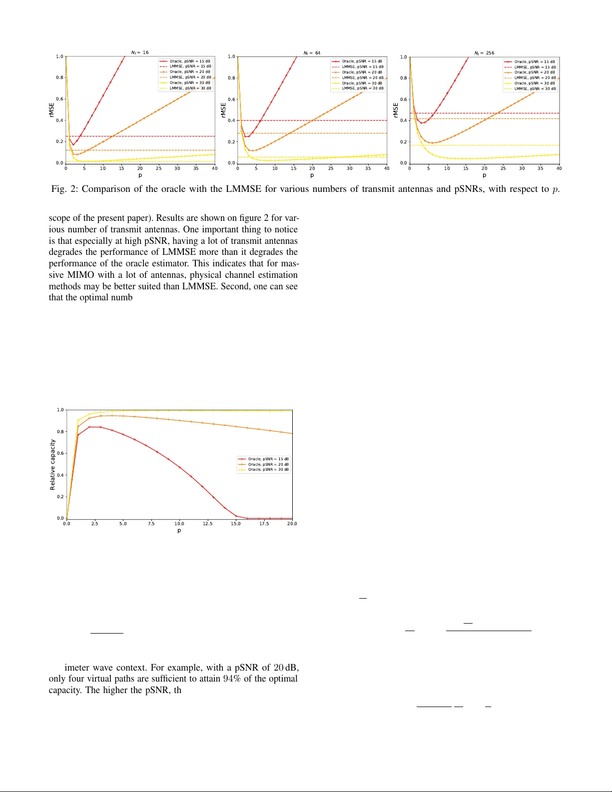
Bias-v ariance tradeof f in MIMO channel estimation Luc Le Magoarou, St ´ ephane Paquelet b <> com , Rennes, France Abstract —Channel estimation is challenging in multi-antenna communication systems, because of the large number of parameters to estimate. It is possible to facilitate this task by using a physical model describing the multiple paths constituting the channel, in the hope of reducing the number of unknowns in the problem. Adjusting the number of estimated paths leads to a bias-variance tradeoff. This paper explores this tradeoff, aiming to find the optimal number of paths to estimate. Moreov er , the approach based on a physical model is compar ed to the classical least squares and Bay esian techniques. Finally , the impact of channel estimation error on the system data rate is assessed. Index T erms —Channel estimation, physical model, MIMO I . I N T RO D U C T I O N Multiple-input multiple-output (MIMO) communication systems allow for a dramatic increase in channel capacity , adding space to the classical time and frequency dimensions [1], [2]. This is done by using sev eral antennas at the transmitter ( N t ) and at the receiver ( N r ). The capacity of MIMO systems is maximized if the channel state is perfectly known at both ends of the link. Channel estimation is deeply impacted by the transition from single antenna to MIMO systems. Indeed, it amounts to determine a complex gain for each transmit/recei ve antenna pair , the narrowband (single carrier) MIMO channel as a whole being usually represented as a matrix H ∈ C N r × N t of such gains. The number of real parameters to estimate is thus 2 N r N t , which may be very lar ge for massive MIMO systems, i.e. systems with up to se veral hundreds of antennas [3], [4]. In a massi ve MIMO context, the classical least squares (LS) estimator is not adapted because the high dimensionality of the parameter space leads to an ill-posed problem. Therefore, in order to add prior information, it has been proposed classically to use Bayesian estimation and thus model the channel matrix as random, gi ving rise to estimators such as the linear minimum mean square error (LMMSE) [5], [6]. Another possibility is to use a parametric model based on the physics of wa ve propagation, in which the channel is expressed as a sum of p paths [7]. Whereas LS and LMMSE estimators ha ve been studied extensi vely in terms of optimal training sequences and performance [8], a similar study is still lacking for channel estimators based on a physical model. Contributions. In this paper , the performance of MIMO channel estimators based on a ph ysical model is studied, highlighting a bias-variance tradeoff driv en by the number of paths p considered by the model. Moreover , physical channel estimators are compared to classical ones in a massiv e MIMO context. Finally , the impact of channel estimation error on the system data rate is theoretically assessed. This work has been performed in the framework of the Horizon 2020 project ONE5G (ICT -760809) receiving funds from the European Union. The authors would like to acknowledge the contributions of their colleagues in the project, although the views expressed in this contribution are those of the authors and do not necessarily represent the project. I I . P RO B L E M F O R M U L A T I O N Notations. Matrices and v ectors are denoted by bold upper-case and lower -case letters: A and a (except 3D “ spatial ” vectors that are denoted − → a ); the i th column of a matrix A by a i ; its entry at the i th line and j th column by a ij . A matrix transpose, conjugate and transconjugate is denoted by A T , A ∗ and A H respecti vely . The trace of a linear transformation represented by A is denoted T r ( A ) . For matrices A and B , A ≥ B means that A − B is positiv e semidefinite. The linear span of a set of vectors A is denoted: span ( A ) . The Kronecker product and vectorization operators are denoted by ⊗ and vec ( · ) respecti vely . The identity matrix is denoted by Id . C N ( µ , Σ ) denotes the standard com- plex gaussian distribution with mean µ and covariance Σ . E ( · ) denotes expectation and cov ( · ) the cov ariance of its argument. A. Channel estimation Consider a narrowband block fading channel between a transmitter and a receiv er with respectively N t and N r antennas. It is represented by the matrix H ∈ C N r × N t , in which h ij corresponds to the channel between the j th transmit and i th receiv e antennas. In order to carry out channel estimation, N s known pilot symbols are sent through the channel by each transmit antenna. The corresponding training matrix is denoted X ∈ C N t × N s . It obeys a power constraint of the form k X k 2 F = P where P is the total training energy . In addition, the transmit power is assumed constant during the training phase, leading to k x i k 2 2 = P e ,i = 1 ,...,N s , which implies P = N s P e . The signal at the receiv e antennas is thus expressed as HX + N , where N is a noise matrix (usually vec ( N ) ∼ C N (0 ,σ 2 Id ) ). One useful quantity is the potential signal to noise ratio (pSNR) defined as pSNR , P e k H k 2 F σ 2 . (1) It is an upper bound on the signal to noise ratio (SNR), which is used to quantify the performance of channel estimators in section III. Note that pSNR and SNR coincide for a rank one channel combined with an optimal precoding at the transmitter , and that with no precoding at all, SNR = pSNR − log 10 ( N t ) (in dB). Due to the high cost and power consumption of millimeter wa ve Radio Frequency (RF) chains, it has been proposed to have less RF chains than antennas in both the transmitter and recei ver [9]–[11]. Such systems are often referred to as hybrid ar chi- tectur es . Mathematically speaking, this translates into sensing the channel through analog precoders v i ∈ C N t , i = 1 ,...,N RF , with N RF ≤ N t , as well as observing the signal at the recei ver through analog combiners denoted w j ∈ C N r , j = 1 ,...,N c . The observed data is thus expressed in all generality as Y = W H HX + W H N , (2) where W , ( w 1 ,..., w N c ) and the training matrix is constrained to be of the form X = VZ , where Z ∈ C N RF × N s is the digital training matrix, and V ∈ C N t × N RF is the analog precoding matrix. For more con venience and to lighten notations, one can introduce the equiv alent vectorized observ ation model: y = Mh + n , (3) where y , vec ( Y ) ∈ C N c N s , h , vec ( H ) ∈ C N r N t , n , vec ( W H N ) ∈ C N c N s and M , X T ⊗ W H ∈ C N c N s × N r N t is called the observation matrix . In the remaining of the paper , it is assumed that the analog combiners are mutually orthogonal and of unit norm: w H i w j = δ ij . This yields k W k 2 F = N c and n ∼ C N (0 ,σ 2 Id ) . Objective. Channel estimation aims at retrie ving h (or equiv alently H ) from the observation of y , knowing the observ ation matrix M and the distrib ution of the noise vector n . The channel estimator is denoted ˆ h (or equi v alently ˆ H in matrix form). At first sight, the search space of channel estimation is thus of dimension 2 N r N t , which may be very large in massi ve MIMO systems (up to se veral thousands). For this reason, classical estimation methods such as the least squares (LS) may not be appropriate. In order to overcome this limitation, some information about the channel has to be used to regularize the problem. For example, the channel can be considered as a random vector whose distribution is kno wn, yielding Bayesian channel estimation [5], [6]. Another possibility is to use a physical channel model, as presented in the next subsection. B. Physical channel model Inspired by the physics of propagation under the plane wa ves assumption, it has been proposed to e xpress the channel as a sum of rank one matrices, each corresponding to a single physical path between transmitter and recei ver . This approach is used by most MIMO channel simulators [12]–[14] and has been validated by propagation measurements. Adopting this kind of modeling and generalizing it to take into account any three-dimensional antenna array geometry , channel matrices take the form H = X P i =1 c i e r ( − → u r,i ) e t ( − → u t,i ) H , (4) where P is the total number of considered physical paths (up to a few hundreds in classical simulators), c i , ρ i e j φ i is the complex gain of the i th path, − → u t,i is the unit vector corresponding to its direction of departure (DoD) and − → u r,i the unit vector corresponding to its direction of arriv al (DoA)(both being described in spherical coordinates by an azimuth angle η and an elev ation angle ψ ). The steering vectors e r ( − → u ) ∈ C N r and e t ( − → u ) ∈ C N t are defined as ( e x ( − → u )) j = 1 √ N x e − j 2 π λ − − → a x,j . − → u for x ∈ { r,t } . The set A x , { − − → a x, 1 ,..., − − − → a x,N x } gathers the positions of the antennas with respect to the centroid of the array (transmit if x = t , recei ve if x = r ). The same model is used in [15]. Estimation model. It makes sense to hav e the channel estimator ˆ H take a form similar to that of the physical channel H gi ven in (4) . It has indeed been proposed in several contexts [16]–[18], leading to estimators expressed as ˆ H = X p k =1 d k e r ( − − → v r,k ) e t ( − → v t,k ) H , (5) where p is the number of paths considered for estimation, called virtual paths . In practice, one takes p P (with p at most a few dozens), because several physical paths can be merged into a single virtual path without harming a lot description accuracy . Indeed, steering vectors associated to close enough directions are almost collinear , yielding a limited angular resolution for the system [7]. Moreov er , a smaller p leads to a better conditioned problem, as will be evidenced in the next section. Let us define the model set M p , A ∈ C N r × N t , A = P p k =1 d k e r ( − − → v r,k ) e t ( − → v t,k ) H to which the estimator made of p virtual paths belongs. By ab use of notation, the vectorized version of this set will be denoted the same way , such that M p = a ∈ C N r N t , a = P p k =1 d k e t ( − → v t,k ) ∗ ⊗ e r ( − − → v r,k ) . Such sets obey the inclusion relation M q ⊂ M q +1 . The estimation model can be seen as a parametric model with parameter vector θ = { θ ( k ) , ( ρ k ,φ k ,η r,k ,ψ r,k ,η t,k ,ψ t,k ) , k = 1 ,..., p } . There are thus 6 p real parameters in this model (the complex gain, DoD and DoA of ev ery path are described with two parameters each). Of course, the model is most useful for estimation in the case where 6 p 2 N r N t , since the number of parameters is thus greatly reduced. Conv ersely , taking p too small may harm the descriptive power of the model. The number of virtual paths p thus drives a tradeoff between complexity and expressi veness, whose study is the object of the next sections. I I I . P E R F O R M A N C E O F E S T I M A T O R S Let us consider an estimator ˆ h of a channel h . Its performance is assessed using the relati ve mean square error (rMSE) defined as rMSE ( ˆ h ) , E " h − ˆ h 2 2 k h k 2 2 # . (6) For any estimator , this error can be decomposed [19] as rMSE ( ˆ h ) = h − E [ ˆ h ] 2 2 k h k 2 2 + T r [ cov ( ˆ h )] k h k 2 2 , (7) where the first term called bias represents the error due to the de viation of the average estimate from the true channel and the second called variance represents the error due to fluctuations around the average. In this section and the following, the rMSE of various channel estimators is studied. The emphasis is put on physical channel estimators, for which a bias-v ariance tradeoff driven by the number of virtual paths p is exhibited. The study of this tradeoff is made possible by the definition of an appropriate oracle estimator . A. Classical channel estimators Let us now revie w the performance of the most classical MIMO channel estimators that are the least squares (LS) and the linear minimum mean square error (LMMSE). This subsection essentially summarizes the main results of [8], in a way that takes into account hybrid systems. LS. The least squares estimator is an unbiased estimator defined (using the vectorized notation of (3)) as ˆ h LS , argmin g k y − Mg k 2 2 = ( M H M ) − 1 M H y . (8) It requires to send N s ≥ N t pilot symbols to exist (for the matrix M H M to be in vertible). In that case, the v ariance (and thus the rMSE) is minimized if the observation matrix obe ys the condition M H M opt = P e N c N s N r N t Id , (9) leading to the optimal performance rMSE opt ( ˆ h LS ) = N r N t pSNR N r N t N c N s . (10) Note that in the case where N s = N t (which corresponds to the minimum number of pilot symbols) and N c = N r (which corresponds to a non-hybrid recei ver), the optimal rMSE is pro- portional to N r N t , showing that such an estimator is not adapted to massiv e MIMO systems in which this quantity is large. LMMSE. The linear minimum mean square error estimator is a Bayesian estimator , meaning that the channel is assumed to be random and to follow a kno wn distrib ution h ∼ C N ( 0 , R ) . A channel realization can then be seen as drawing at random a user location in a giv en region in a fixed en vironment: the smaller the region the closer to singular R . Note that in practice the cov ariance matrix R has to be estimated using previous channel estimates.If R is perfectly known, the LMMSE is the linear estimator minimizing the MSE, it takes the form ˆ h LMMSE , RM H MRM H + σ 2 Id − 1 y , (11) with RM H MRM H + σ 2 Id − 1 = argmin A E h k h − Ay k 2 2 i , where the expectation is taken over both the noise and the channel distributions. In that case, the rMSE is minimized if the observation matrix obeys the condition (for a high enough SNR, see [8, section V] for more details) M H M opt = P e N c N s N r N t + σ 2 N r N t T r R − 1 Id − σ 2 R − 1 . (12) This leads to the optimal performance rMSE opt ( ˆ h LMMSE ) = 1 E [ pSNR ] N r N t N c N s N r N t + Tr [ R − 1 ] Tr [ R ] ( N r N t ) 2 . (13) In this expression, the first term at the denominator E [ pSNR ] N r N t N c N s N r N t corresponds to the expected in verse of the optimal LS performance, indicating that the LMMSE should exhibit the same behaviour for massi ve MIMO systems. Howe ver , the second term Tr [ R − 1 ] Tr [ R ] ( N r N t ) 2 may compensate for the first one. This term is lower-bounded by one (if all the eigenv alues of R are equal), and grows as the eigenv alues distribution becomes more uneven (if R is closer to be singular). Simply put, the distribution of the eigen values of R determines to which extent knowing it is informati ve for channel estimation. The cov ariance being estimated in practice with pre vious channel estimates, the smaller the used time interval, the closer to singular R (since the user stayed in a smaller region), so that it giv es more information and the optimal rMSE is reduced. B. Physical channel estimators As seen in the previous subsection, the LS and LMMSE estimators have been theoretically studied, and their performance is well understood. In contrast, estimators based on a physical model taking the form of (5) hav e not been in vestigated as deeply . This may be due to the difficulty to study jointly the bias and variance terms of the rMSE. T o overcome this difficulty , an oracle estimator is introduced here which allo ws to separate the analysis of the bias from that of the variance. This oracle should be seen as a tool to study theoretically estimators based on a physical model, and its rele v ance with respect to practical estimators is assessed in section VI. Oracle definition. First, one can notice that for an estimator ˆ h ∈ M p , rMSE ( ˆ h ) ≥ h − proj M p ( h ) 2 2 k h k 2 2 . where proj M p ( u ) , argmin a ∈M p k u − a k . Then, the oracle estimator ˆ h oracle is defined as the unbiased efficient estimator of proj M p ( h ) . In other words, the oracle property amounts to consider that M proj M p ( h ) + n is observed instead of Mh + n , and thus ignore the part of the channel that is orthogonal to the model set M p . Mathematically speaking, using the oracle allows to study separately the bias and variance terms of the rMSE, as done below . Intuitively , the v ariance should increase with p whereas the bias should decrease, since p represents the complexity/e xpressi veness of the model. V ariance. The oracle being efficient means that T r [ cov ( ˆ h oracle )] = CRB where CRB is the Cram ´ er-Rao lower bound [20], [21]. This bound has been deriv ed in [15], leading to the following bound for the variance term of (7). Theorem 1. The variance of the oracle estimator is given by T r [ cov ( ˆ h oracle )] k h k 2 2 ≥ 3 p pSNR . (14) The important feature of this result is the fact that the bound on the variance is proportional to the number of virtual paths p (see [15] for the proof of the theorem). Moreover , denoting proj M p ( h ) = X p i =1 b i e t ( − − → w t,i ) ∗ ⊗ e r ( − − → w r,i ) , (15) the inequality is replaced by an equality in the theorem if the observation matrix M = X T ⊗ W H obeys the two conditions span [ p i =1 n e t ( − − → w t,i ) , ∂ e t ( − − → w t,i ) ∂ η t,i , ∂ e t ( − − → w t,i ) ∂ ψ t,i o ⊂ im ( X ) , span [ p i =1 n e r ( − − → w r,i ) , ∂ e r ( − − → w r,i ) ∂ η r,i , ∂ e r ( − − → w r,i ) ∂ ψ r,i o ⊂ im ( W ) . Note that the variance is in that case directly proportional to the number of parameters to estimate. Moreov er the result is pretty general. Indeed, for example if the receiv er (or transmitter) has only one antenna, the theorem remains valid with the right-hand side of (14) becoming 2 p pSNR , since the two parameters corresponding to the DoA (or DoD) of each virtual path disappear , leading to only four parameters per path. Bias. The oracle being unbiased with respect to proj M p ( h ) means that E [ ˆ h oracle ] = proj M p ( h ) . In that case, the bias term of (7) becomes h − E [ ˆ h oracle ] 2 2 k h k 2 2 = h − proj M p ( h ) 2 2 k h k 2 2 . (16) The study of this bias term is the main contrib ution of this paper . It is carried out in the next section. I V . B I A S O F P H Y S I C A L C H A N N E L E S T I M A T O R S Computing the bias of the oracle estimator ˆ h oracle defined abov e amounts to compute the projection proj M p ( h ) . Unfortu- nately , ev en considering a discretized set of candidates DoAs and DoDs, this problem (which then becomes a sparse approximation problem) is NP-hard [22]. The projection can be approximated numerically using sparse recovery methods, as will be done in section VI. Howe ver the objectiv e of this section is to study theoretically the bias and gi ve an interpretable upper bound. Assumptions. Let us consider in this section the simpler case in which the transmitter or receiver has only one antenna ( N t = 1 or N r = 1 ). In that case, the physical channel h and its estimator ˆ h ∈ M p are expressed h = X P i =1 c i e ( − → u i ) , ˆ h = X p k =1 d k e ( − → v k ) , where the indices denoting transmitter or receiv er have been dropped since they are useless (they will be dropped in each nota- tion defined in section II-B used in this section). This assumption allows to lighten considerably the notations in the follo wing de velopment. Ho we ver , the general method used to bound the bias remains valid in the general model given by (4) and (5) . Bound on the bias. Starting from (16), the inequality h − E [ ˆ h oracle ] 2 ≤ h − ˆ h 2 is true for any ˆ h ∈ M p (by definition of the projection). In particular , it is true when using the following suboptimal strategy to define ˆ h : 1) Partition the set of P physical paths into p subsets R k ,k = 1 ,...,p , of paths with close directions. 2) Assign one virtual path of direction − → v k to each subset R k . 3) Set d k as the optimal coefficient to approximate the paths in each subset R k by d k e ( − → v k ) , giv en the direction − → v k . The two first steps of this strate gy amount to write h − ˆ h = X p k =1 h X i ∈R k c i e ( − → u i ) − d k e ( − → v k ) i , and the last one yields d k = P i ∈R k c i e ( − → v k ) H e ( − → u i ) (this is the coef ficient of the orthogonal projection onto e ( − → v k ) ). In that case, h − ˆ h 2 = p X k =1 h X i ∈R k c i e ( − → u i ) − e ( − → v k ) H e ( − → u i ) e ( − → v k ) i 2 ≤ p X k =1 X i ∈R k c i e ( − → u i ) − e ( − → v k ) H e ( − → u i ) e ( − → v k ) 2 = p X k =1 X i ∈R k | c i | q 1 − | e ( − → v k ) H e ( − → u i ) | 2 , where the second line is obtained by applying the triangle inequality twice and the third by simply dev eloping the norm in the second one. At this point, the bias is bounded by a sum o ver all physical paths, each term being a quantity p 1 − | e ( − → v k ) H e ( − → u i ) | 2 measuring the non-collinearity of the steering vectors corresponding to the physical path and to the associated virtual path, weighted by the modulus of its physical coefficient | c i | . T o go further, let us analyze in details the scalar product between steering vectors appearing in the previous inequality . Its expression is gi ven by e ( − → v k ) H e ( − → u i ) = 1 N X N n =1 e − j 2 π λ − → a n . ( − → u i − − → v k ) . Using the infinite series representation of the exponential function leads to the follo wing result. Lemma 1. pr ovided k − → u i − − → v k k 2 < 1 √ 2 π − → a n λ 2 , ∀ n , q 1 − | e ( − → v k ) H e ( − → u i ) | 2 ≤ 2 π k − → u i − − → v k k 2 s 1 N X N n =1 − → a n λ 2 2 cos 2 − → a n , ( − → u i − − → v k ) . The proof is given in appendix A. If the condition of the lemma is fulfilled by each physical path (if there are enough virtual paths with appropriate directions), this yields h − E [ ˆ h oracle ] 2 ≤ p X k =1 X i ∈R k 2 π | c i |k − → u i − − → v k k 2 v u u t 1 N N X n =1 − → a n λ 2 2 cos 2 − → a n , ( − → u i − − → v k ) . Interpr etations. First, notice that the part under the square root represents the angular sensitivity of the antenna array: it is bounded by the quantity κ ( A ) , q 1 N P N n =1 − → a n λ 2 2 which depends only on the antenna array geometry (lar ger antenna arrays e xhibit more angular sensiti vity). Second, let us assess the dependency of the bound to p . T o do so, assume that the assign- ment of physical paths to virtual paths is done by partitioning a given portion of the sphere in p regions and assigning all the physical paths whose direction falls into the k th region to the k th virtual path, whose direction is at the center of the region. That way , the bound is obviously decreasing when p increases, since adding a virtual path reduces the distance k − → u i − − → v k k 2 for paths of the ne w region. The rate at which it decreases depends on the physical directions distribution. For example, in the worst-case scenario of uniformly distributed paths over a giv en portion of the sphere and regions of equal size, each of the p regions gathers of the order of 1 p physical paths and the typical distance to the center of each region is of the order of 1 √ p . This leads to a bound of the order of p × 1 p × 1 √ p = 1 √ p and consequently to a bias in (16) of the order of 1 p at worst. The bias is e valuated numerically for realistic paths distributions in section VI. Finally , this bound lends itself to nice interpretations, b ut may be loose. A way of improving the bound is discussed in appendix B. V . I M PAC T O N T H E DAT A R A T E In order to assess the influence of channel estimation on the system performance, the rMSE in itself is of little use. Instead, the data rate loss caused by the estimation error (which leads to imperfect precoding) should be e v aluated. T o do so, assuming a transmission model of the form z = Hx + n after channel estimation has been performed and optimal nearest neighbour decoding [9], the channel capacity C = log 2 det Id + E nn H − 1 H E xx H H H should be studied. Gi ven the noise covariance E nn H = σ 2 Id and the channel singular v alue decomposition (SVD) H = UΛV H , the optimal signal covariance is giv en by E xx H opt = VD V H , where the diagonal matrix D corresponds to the optimal power allocation (computed by water -filling). Let us assume here that the channel is fixed but unkno wn to the system, which uses an estimate ˆ H instead (see [23] for a similar model). Moreover , gi ven the SVD ˆ H = ˆ U ˆ Λ ˆ V H , assume that the signal cov ariance is taken according to the imperfect estimate as E xx H = ˆ V ˆ D ˆ V H , leading to a mismatched precoder . In that case, C = C opt − C loss , with C opt = log 2 det Id + 1 σ 2 ΛDΛ H and C loss = − log 2 det Id + A Λ V H ˆ V ˆ D ˆ V H V − D Λ with A = 1 σ 2 Id + 1 σ 2 ΛDΛ H − 1 (see [23] for more details). This e xpression is difficult to study in the general case. Howe ver , it simplifies if the receiv er has only one antenna ( N r = 1 ), to C opt = log 2 (1 + pSNR ) and C loss = C opt − log 2 1 + |h h , ˆ h i| 2 k h k 2 2 k ˆ h k 2 2 pSNR . (17) This capacity loss can be linked to the rMSE of channel estimation by the following bound: C loss ≤ C opt − log 2 1 + pSNR 1 − rMSE ( ˆ h ) 2 − rMSE ( ˆ h ) , (18) prov en in appendix C. Note that the bound is v alid as soon as rMSE ≤ 1 . This bound giv es a worst-case data rate loss depending only on the rMSE and the pSNR. It is used in section VI to assess this loss for realistic channels. V I . E X P E R I M E N T S The objective of this section is to assess empirically the mathe- matical de velopments of the previous sections by: determining if using the oracle estimator makes sense, comparing physical chan- nel estimators to others and quantifying the data rate loss caused by physical channel estimation. All experiments performed here are done using realistic channels generated with help of the NYUSIM channel simulator [12], in a millimeter wav e massiv e MIMO downlink context. In particular , the frequency is set to f = 28 GHz and the distance between transmitter and receiv er to d = 30 m to obtain the DoDs, DoAs, gains and phases of each path. The channel matrix is then obtained from (4) (with the total number of physical paths P between fifty and a hundred), consid- ering a square uniform planar array (UP A) with half-wa velength separated antennas with N t = 64 (unless otherwise stated) at the transmitter and a single antenna recei ver ( N r = 1 ). All results sho wn here are averages ov er one hundred channel realizations. Relevance of the oracle. First, the goal is to determine whether or not the estimator ˆ h oracle has a behavior close to practical estimators. T o do so, the bias of the oracle (16) is numerically e v aluated by computing proj M p ( h ) with help of the orthogonal matching pursuit algorithm (OMP) [24], called directly on h (without noise). The variance of ˆ h oracle is taken directly as (14) with an equality (assuming optimal observations), and its rMSE is obtained by summing bias and variance. The oracle is compared to a practical estimator taking as input noisy observ ations of h , as in (3) with an optimal observation matrix, using OMP to get channel estimates. Results in terms of rMSE with respect to the number of virtual paths p for various pSNRs are shown on figure 1, in which the bias and v ariances of the oracle are also plotted (in black) to enhance clarity . First, one can notice that the oracle and the practical estimator exhibit a similar bias variance tradeoff, especially at high pSNR (note that for 64 antennas and no precoding, pSNR = SNR + 18 dB). This allo ws to confirm that the oracle estimator is rele vant, because it allo ws a separate study of the bias and variance while providing accurate performance predictions. Note that for a high p , the OMP estimator leads to a lower rMSE than the oracle, this is because it yields biased estimates with respect to the projection onto the model (thus the bound on the v ariance does not apply). Finally , note that the optimal number of virtual paths p yielding the smallest rMSE is very small compared to the number of physical paths P , (no more than a dozen against more than fifty), showing empirically that physical paths can indeed be merged into fewer virtual paths with little accuracy loss. 0 5 10 15 20 25 30 35 40 p 0.0 0.2 0.4 0.6 0.8 1.0 rMSE Bias Variance Oracle, pSNR = 15 dB Oracle, pSNR = 20 dB Oracle, pSNR = 30 dB OMP, pSNR = 15 dB OMP, pSNR = 20 dB OMP, pSNR = 30 dB Fig. 1: Oracle compared to the OMP algorithm for various pSNRs, with respect to p . Comparison with LMMSE. Let us now compare the oracle to other estimators presented in section III-A. Actually , the comparison is performed here with the LMMSE only , the comparison with the LS estimator not being shown for readability and brevity reasons. This is justified by the fact that the LS is always worse than the LMMSE in terms of optimal rMSE, but the same trends are observed, due to the similar expressions of the optimal performance (10) and (13) , leading to the same con- clusions. The performance of LMMSE is taken according to (13) , assuming the covariance matrix R is perfectly known, and taking Tr [ R − 1 ] Tr [ R ] ( N r N t ) 2 = 2 (this choice is rather arbitrary , but the point here is to show the relativ e behavior of the methods, assessing this quantity in practice would of course be v aluable b ut is out of the 0 5 10 15 20 25 30 35 40 p 0.0 0.2 0.4 0.6 0.8 1.0 rMSE N t = 1 6 Oracle, pSNR = 15 dB LMMSE, pSNR = 15 dB Oracle, pSNR = 20 dB LMMSE, pSNR = 20 dB Oracle, pSNR = 30 dB LMMSE, pSNR = 30 dB 0 5 10 15 20 25 30 35 40 p 0.0 0.2 0.4 0.6 0.8 1.0 rMSE N t = 6 4 Oracle, pSNR = 15 dB LMMSE, pSNR = 15 dB Oracle, pSNR = 20 dB LMMSE, pSNR = 20 dB Oracle, pSNR = 30 dB LMMSE, pSNR = 30 dB 0 5 10 15 20 25 30 35 40 p 0.0 0.2 0.4 0.6 0.8 1.0 rMSE N t = 2 5 6 Oracle, pSNR = 15 dB LMMSE, pSNR = 15 dB Oracle, pSNR = 20 dB LMMSE, pSNR = 20 dB Oracle, pSNR = 30 dB LMMSE, pSNR = 30 dB Fig. 2: Comparison of the oracle with the LMMSE for v arious numbers of transmit antennas and pSNRs, with respect to p . scope of the present paper). Results are shown on figure 2 for var - ious number of transmit antennas. One important thing to notice is that especially at high pSNR, having a lot of transmit antennas degrades the performance of LMMSE more than it de grades the performance of the oracle estimator . This indicates that for mas- si ve MIMO with a lot of antennas, physical channel estimation methods may be better suited than LMMSE. Second, one can see that the optimal number of virtual paths to consider for the oracle estimator grows with the number of antennas. This behavior was expected from the bound on the bias gi ven in section IV, since the quantity κ ( A ) gro ws with N t (the angular resolution increases). Finally , note that e ven though the curv es indicate that the estimation task is harder for a greater number of antennas at constant pSNR, high pSNRs are easier to attain with a lot of antennas since according to (1), pSNR is proportional to N t . 0.0 2.5 5.0 7.5 10.0 12.5 15.0 17.5 20.0 p 0.0 0.2 0.4 0.6 0.8 1.0 Relative capacity Oracle, pSNR = 15 dB Oracle, pSNR = 20 dB Oracle, pSNR = 30 dB Fig. 3: Relative capacity with respect to p for various pSNRs. Impact on data rate. Finally , let us quantify the data rate loss caused by the estimation error when using a physical model, with respect to the number of considered virtual paths. T o do so, the bound (17) is used with the rMSE of the oracle estimator , the results being shown on figure 3, where the relative capacity is defined as C opt − C loss C opt . These curves sho w it is sufficient to estimate very fe w virtual paths to guarantee a data rate close to the optimal one (obtained if the channel is perfectly known) in the tested millimeter wav e context. For example, with a pSNR of 20 dB, only four virtual paths are sufficient to attain 94 % of the optimal capacity . The higher the pSNR, the higher the optimal (in terms of capacity) number of virtual paths to estimate, which makes sense, since more physical paths are then above the noise le vel. V I I . C O N C L U S I O N In this paper, the performance of MIMO channel estimators using a physical model was theoretically studied. T o do so, an appropriate oracle estimator was defined which allo wed to study separately the bias and v ariance terms of the rMSE. The variance term ha ving been already studied in a previous work [15], the present paper focused on the bias term, which was bounded by an interpretable quantity depending both on the propagation properties of the channel and on the antenna arrays geometries. Moreover , the data rate loss caused by the channel estimation error was bounded by a quantity depending only on the rMSE and the pSNR. Then, the defined oracle, whose rele vance was empirically confirmed on realistic channels in a millimeter wav e massiv e MIMO context, was compared to the classical LMMSE estimator , showing that channel estimators based on a physical model may be better suited to systems with a large number of antennas. Finally , it was shown empirically that estimating very few virtual paths is sufficient to guarantee a data rate close to the optimum in the aforementioned context. In the future, it would be of great interest to perform extensi ve comparisons between physical channel estimators and other types of estimators such as the LMMSE, with the objecti ve to see emerge different characteristic settings in which one or the other type of estimator is more adapted. Such a study would be v ery useful for system design. On a more technical side, improving the bound on the bias proposed here should be possible, as mentioned in appendix B. A P P E N D I X A. Pr oof of lemma 1 Using the series representation of the exponential e x = P + ∞ l =0 x l l ! , the scalar product is expressed e ( − → v k ) H e ( − → u i ) = 1 N N X n =1 + ∞ X l =0 − j 2 π λ − → a n . ( − → u i − − → v k ) l l ! . Using P N n =1 − → a n = 0 since the antennas are located with respect to the centroid of the array , the term l = 1 is null, leading to e ( − → v k ) H e ( − → u i ) = 1 + + ∞ X l =2 − j2 π l l ! 1 N N X n =1 1 λ − → a n . ( − → u i − − → v k ) l . Both the real and imaginary parts of this series are alternating series. The terms are decreasing in magnitude if 1 l ! 2 π λ − → a n . ( − → u i − − → v k ) l > 1 ( l + 2)! 2 π λ − → a n . ( − → u i − − → v k ) ( l +2) , ∀ n. This condition is fulfilled as soon as k − → u i − − → v k k 2 < 1 √ 2 π − → a n λ 2 , ∀ n, (taking l = 0 and applying the Cauchy-Schwarz inequality). In that case, Re e ( − → v k ) H e ( − → u i ) ≥ 1 − 2 π 2 1 N P N n =1 1 λ − → a n . ( − → u i − − → v k ) 2 . Using 1 − e ( − → v k ) H e ( − → u i ) 2 ≤ 1 − Re e ( − → v k ) H e ( − → u i ) 2 and Re e ( − → v k ) H e ( − → u i ) 2 ≥ 1 − 4 π 2 1 N P N n =1 1 λ − → a n . ( − → u i − − → v k ) 2 , 1 − e ( − → v k ) H e ( − → u i ) 2 ≤ 4 π 2 1 N X N n =1 1 λ − → a n . ( − → u i − − → v k ) 2 . Dev eloping the scalar product proves the lemma. B. Impr oving the bound The bound of this paper is obtained applying the triangle inequality twice in a row , which may lead to a loose bound. Instead, one could apply it only once to get h − ˆ h 2 ≤ p X k =1 X i ∈R k c i e ( − → u i ) − e ( − → v k ) H e ( − → u i ) e ( − → v k ) 2 . At this point, one can notice that each term of the sum, when squared, corresponds to a quadratic form X i ∈R k c i e ( − → u i ) − e ( − → v k ) H e ( − → u i ) e ( − → v k ) 2 2 = c H Qc , where c = ( c 1 ,...,c |R k | ) T and Q ∈ C |R k |×|R k | with q ij = e ( − → u i ) H e ( − → u j ) − e ( − → u i ) H e ( − → v k ) e ( − → v k ) H e ( − → u j ) . Studying the properties of the matrix Q may lead to a tighter bound, but is not guaranteed to lead to interpretable results. C. Pr oof of (18) Starting from (17), one can first notice that |h h , ˆ h i| 2 k h k 2 2 k ˆ h k 2 2 ≥ Re ( h h , ˆ h i ) 2 k h k 2 2 k ˆ h k 2 2 , with Re ( h h , ˆ h i ) 2 k h k 2 2 k ˆ h k 2 2 = 1 + 1 4 h k h k 2 − ˆ h k ˆ h k 2 4 2 − h k h k 2 − ˆ h k ˆ h k 2 2 2 . Then, writing z , h k h k 2 − ˆ h k ˆ h k 2 2 2 = 2 k h − ˆ h k 2 2 k h k 2 2 − 2 x 2 + 4 αx − 2 α with x , k ˆ h k 2 k h k 2 and α , Re ( h h , ˆ h i ) k h k 2 k ˆ h k 2 , the bound z = h k h k 2 − ˆ h k ˆ h k 2 2 2 ≤ 2 k h − ˆ h k 2 2 k h k 2 2 = 2 rMSE holds if rMSE ≤ 1 . Indeed, in that case Re ( h h , ˆ h i ) ≥ 0 which yields − 2 x 2 + 4 αx − 2 α ≤ 0 . The function 1 + z 2 4 − z decreases for z ≤ 2 , which finishes the proof yielding |h h , ˆ h i| 2 k h k 2 2 k ˆ h k 2 2 ≥ 1 − rMSE (2 − rMSE ) . R E F E R E N C E S [1] Emre T elatar, “Capacity of multi-antenna gaussian channels, ” European transactions on telecommunications , v ol. 10, no. 6, pp. 585–595, 1999. [2] David Tse and Pramod V iswanath, Fundamentals of wir eless communication , Cambridge uni versity press, 2005. [3] Fredrik Rusek, Daniel Persson, Buon Kiong Lau, Erik G Larsson, Thomas L Marzetta, Ove Edfors, and Fredrik T ufvesson, “Scaling up mimo: Opportunities and challenges with very large arrays, ” IEEE Signal Pr ocessing Magazine , vol. 30, no. 1, pp. 40–60, 2013. [4] Erik G Larsson, Ove Edfors, Fredrik T ufvesson, and Thomas L Marzetta, “Massive mimo for next generation wireless systems, ” IEEE Communications Magazine , vol. 52, no. 2, pp. 186–195, 2014. [5] Emil Bj ¨ ornson, Jakob Ho ydis, Luca Sanguinetti, et al., “Massive mimo networks: Spectral, energy , and hardware ef ficiency , ” F oundations and T rends® in Signal Pr ocessing , vol. 11, no. 3-4, pp. 154–655, 2017. [6] Samer Bazzi and W en Xu, “Downlink training sequence design for fdd multiuser massive mimo systems, ” IEEE T ransactions on Signal Pr ocessing , vol. 65, no. 18, pp. 4732–4744, 2017. [7] Akbar M Sayeed, “Deconstructing multiantenna fading channels, ” IEEE T ransactions on Signal Pr ocessing , vol. 50, no. 10, pp. 2563–2579, 2002. [8] Mehrzad Biguesh and Ale x B Gershman, “T raining-based mimo channel estimation: a study of estimator tradeof fs and optimal training signals, ” IEEE transactions on signal processing , vol. 54, no. 3, pp. 884–893, 2006. [9] Omar El A yach, Sridhar Rajagopal, Shadi Abu-Surra, Zhouyue Pi, and Robert W Heath, “Spatially sparse precoding in millimeter wave mimo systems, ” IEEE T ransactions on W ireless Communications , vol. 13, no. 3, pp. 1499–1513, 2014. [10] Robert W Heath, Nuria Gonzalez-Prelcic, Sundeep Rangan, W onil Roh, and Akbar M Sayeed, “ An overvie w of signal processing techniques for millimeter wa ve mimo systems, ” IEEE journal of selected topics in signal pr ocessing , vol. 10, no. 3, pp. 436–453, 2016. [11] Akbar M. Sayeed and John H. Brady , Millimeter-W ave MIMO T ransceivers: Theory , Design and Implementation , pp. 231–253, John W iley & Sons, Ltd, 2016. [12] Shu Sun, George R MacCartney Jr , and Theodore S Rappaport, “ A novel millimeter-wa ve channel simulator and applications for 5g wireless communications, ” in IEEE International Confer ence on Communications (ICC) , 2017. [13] Stephan Jaeckel, Leszek Raschko wski, Kai B ¨ orner , and Lars Thiele, “Quadriga: A 3-d multi-cell channel model with time e volution for enabling virtual field trials, ” IEEE T ransactions on Antennas and Pr opagation , v ol. 62, no. 6, pp. 3242–3256, 2014. [14] 3GPP TR 38.901 v14.1.0, “Study on channel model for frequencies from 0.5 to 100 ghz, ” T ech. Rep., 2017. [15] Luc Le Magoarou and St ´ ephane Paquelet, “Parametric channel estimation for massiv e MIMO, ” in IEEE Statistical Signal Pr ocessing W orkshop (SSP) , 2018. [16] W . U. Bajwa, J. Haupt, A. M. Sayeed, and R. Nowak, “Compressed channel sensing: A new approach to estimating sparse multipath channels, ” Pr oceedings of the IEEE , v ol. 98, no. 6, pp. 1058–1076, June 2010. [17] Ahmed Alkhateeb, Omar El A yach, Geert Leus, and Robert W Heath, “Channel estimation and hybrid precoding for millimeter wav e cellular systems, ” IEEE Journal of Selected T opics in Signal Pr ocessing , vol. 8, no. 5, pp. 831–846, 2014. [18] Kiran V enugopal, Ahmed Alkhateeb, Nuria Gonz ´ alez Prelcic, and Robert W Heath, “Channel estimation for hybrid architecture-based wideband millimeter w av e systems, ” IEEE Journal on Selected Areas in Communications , v ol. 35, no. 9, pp. 1996–2009, 2017. [19] Stev en M. Kay , Fundamentals of Statistical Signal Pr ocessing: Estimation Theory , Prentice-Hall, Inc., Upper Saddle Ri ver, NJ, USA, 1993. [20] Calyampudi Radakrishna Rao, “Information and the accuracy attainable in the estimation of statistical parameters, ” Bulletin of the Calcutta Mathematical Society , v ol. 37, pp. 81–89, 1945. [21] Harald Cram ´ er , Mathematical Methods of Statistics , vol. 9, Princeton univ ersity press, 1946. [22] J.A. Tropp and S.J. Wright, “Computational methods for sparse solution of linear inverse problems, ” Pr oceedings of the IEEE , vol. 98, no. 6, pp. 948–958, June 2010. [23] June Chul Roh and Bhaskar D Rao, “Design and analysis of mimo spatial multiplexing systems with quantized feedback, ” IEEE transactions on signal pr ocessing , vol. 54, no. 8, pp. 2874–2886, 2006. [24] J.A. T ropp and A.C. Gilbert, “Signal reco very from random measurements via orthogonal matching pursuit, ” Information Theory, IEEE T ransactions on , vol. 53, no. 12, pp. 4655–4666, Dec 2007.
Original Paper
Loading high-quality paper...
Comments & Academic Discussion
Loading comments...
Leave a Comment