A Joint Combiner and Bit Allocation Design for Massive MIMO Using Genetic Algorithm
In this paper, we derive a closed-form expression for the combiner of a multiple-input-multiple-output (MIMO) receiver equipped with a minimum-mean-square-error (MMSE) estimator. We propose using variable-bit-resolution analog-to- digital converters …
Authors: I. Zakir Ahmed, Hamid Sadjadpour, Shahram Yousefi
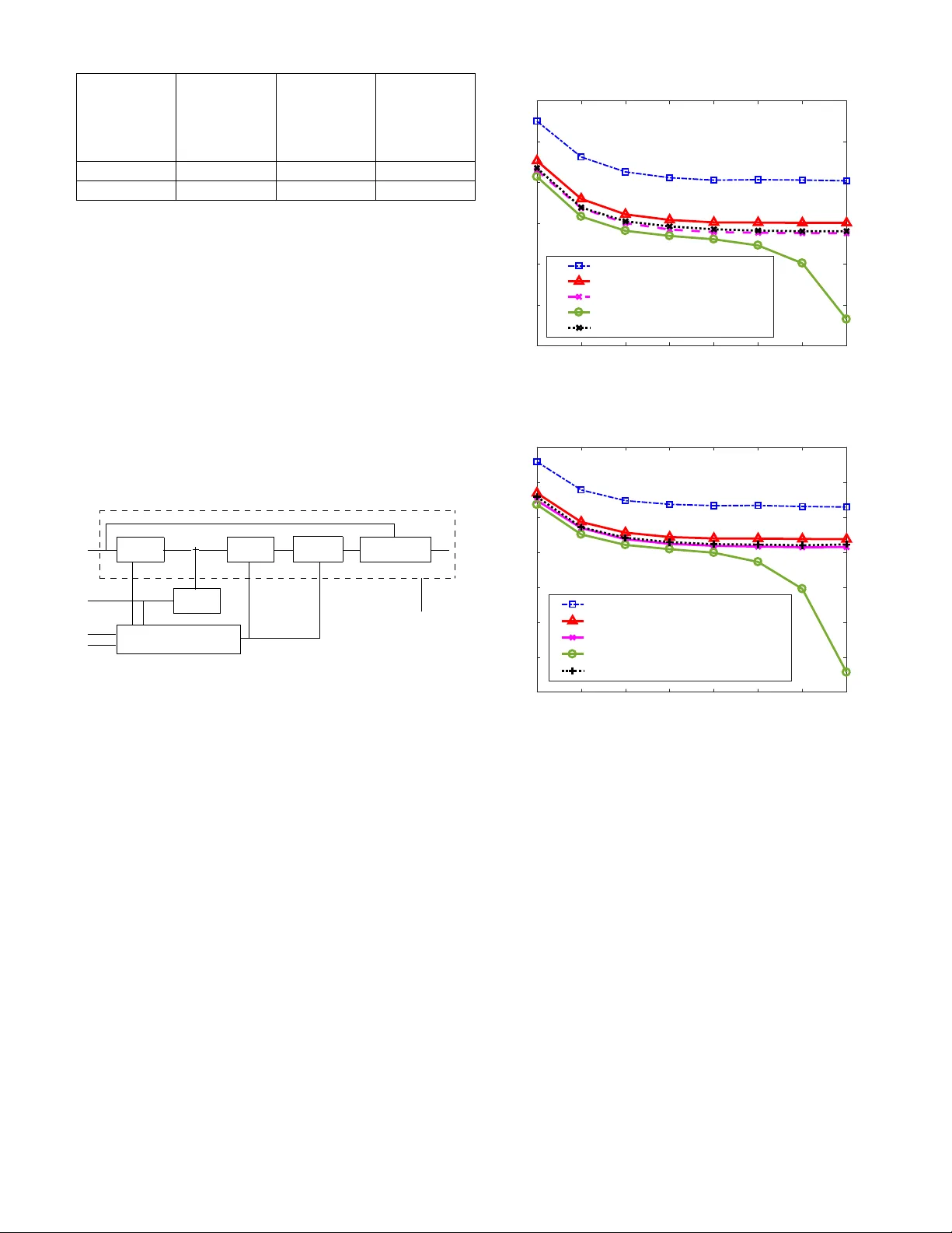
A Joint Combiner and Bit Allocation Design for Massi v e MIMO Using Genetic Algorithm I. Zakir Ahmed and Hamid Sadjadpour Department of Electrical Engineering Univ ersity of California, Santa Cruz Shahram Y ousefi Department of Electrical and Computer Engineering Queen’ s Univ ersity , Canada Abstract —In this paper , we derive a closed-form expression for the combiner of a multiple-input-multiple-output (MIMO) recei ver equipped with a minimum-mean-square-err or (MMSE) estimator . W e propose using variable-bit-r esolution analog-to- digital con verters (ADC) across radio frequency (RF) paths. The combiner designed is a function of the quantization errors across each RF path. Using very low bit resolution ADCs (1-2bits) is a popular approach with massive MIMO r eceiver architectures to mitigate large power demands. W e show that for certain channel conditions, adopting unequal bit resolution ADCs (e.g., between 1 and 4 bits) on differ ent RF chains, along with the proposed combiner , improv es the performance of the MIMO recei ver in the Mean Squared Error (MSE) sense. The variable-bit-resolution ADCs is still within the power constraint of using equal bit resolution ADCs on all paths (e.g., 2-bits). W e propose a genetic algorithm in conjunction with the derived combiner to arrive at an optimal ADC bit allocation framework with significant reduction in computational complexity . I . I N T R O D U C T IO N In mmW ave massive MIMO, a large antenna array is used to form a beam at the receiver . In the Multi-User (MU) case, each user equipment (UE) with its antenna array typically forms a beam to the receiv er , which is either a Base Station (BS) or an Access Point (AP). The receiv er attempts to spatially decorrelate the signal from N such UEs. A Hybrid precoding/combining is a common architecture used with mmW av e massiv e MIMO transcei vers [ 1 ] , [ 3 ] , [ 4 ] . At the receiv er, the analog combining will combine the beams and a digital combiner spatially demultiplex es the signals from N users or streams. The combination of analog and digital precoding and combining will increase the performance of the communication system for a giv en channel realization [ 1 ] , [ 3 ] . In another architecture of MU massiv e MIMO operating at sub-6 Ghz frequencies, the BS with tens to hundreds of anten- nas would receiv e signals from N UEs (which typically could be single antenna systems) [ 2 ] . The BS will demultiplex the signal from N UEs. In both scenarios, the spatial multiplexing of streams increases the capacity of the system linearly with increasing N [ 5 ] . Howe ver , this imposes hardware and particularly power constraints with increasing number of users or independent spatial streams (RF chains) [ 3 ] . The biggest part of the power consumption on the receiver side is from ADCs. The power consumed by the ADCs is exponential in the number of bits (resolution) and directly proportional to the bandwidth of the signal [ 3 ] , [ 6 ] and [ 7 ] . Prior works analyze the performance of the receivers with 1-bit ADCs to constraint power [ 1 ] , [ 2 ] , [ 3 ] . Mixed ADCs with variable bits for each RF chains were proposed in [ 6 ] , [ 7 ] , [ 8 ] . The intent has been to improve the performance of the receiv er by increasing the ADC bit resolution by more than 1 bit at a small sacrifice of power . Howe ver the analysis is done with equal bit ADCs on all RF Paths. Distributing the bits unequally across RF paths with power constraint was explored in [ 8 ] . In [ 8 ] , a bit allocation strategy was arriv ed in the closed form with a fix ed combiner . In our work, we deriv e the expression for the combiner based on the MMSE criteria which is dependent on the channel. The combiner designed is a function of ADC bit allocation. An optimal bit allocation is obtained using a genetic algorithm together with the help of the combiner designed in the first step. The proposed combiner and bit allocation will be part of digital combining block of the hybrid combining technique for mmW av e massiv e MIMO architecture or simply a linear digital combiner in a massiv e MU-MIMO framew ork for sub-6 Ghz frequencies. W e present the simulation results with number of RF paths equal to 8 and 12 using channel models in [ 5 ] , [ 9 ] . W e observe that the combined optimal bit allocation and combiner under a giv en power constraint does not always result in equal distribution of bits to all streams (RF chains); howe ver would depend on the channel H . I I . S I G N A L M O D E L In this work, we consider a signal model that captures a variety of MIMO communication systems. T wo such exam- ples are: (i) multi-user, multiple-input-multiple-output (MU- MIMO) uplink scenario in which Base Station (BS) with M antennas receiv e signal from N single-antenna User Equip- ment (UEs) [ 2 ] , [ 7 ] and (ii) a mmW av e MU-MIMO communi- cation link with hybrid combining where the receiv er consists of large number of antennas. T ypically , a Uniform Linear Array (ULA) of fers combining via analog beamformers and digital combiners [ 1 ] , [ 3 ] , [ 4 ] . In (i), the channel H = [ h ij ] is a M × N rich scattering matrix with h ij ∼ N (0 , 1) . The received signal is giv en by r = √ p u Hx + n , (1) where p u is the av erage power transmitted per symbol, M >> N , r is an M × 1 receiv e symbol vector; x is an N × 1 transmitted signal vector , and n is an M × 1 noise vector with entries independent and identically distributed (i.i.d) random variables having complex Gaussian distribution with n ∼ C N ( 0 , σ 2 n I M ) : In (ii), a mmW ave which is either Single-User MIMO (SU- MIMO) or MU-MIMO communication link is considered with hybrid combining. In SU-MIMO case, the communication link is between a single UE and either an AP or BS. In this case, there are N parallel streams of data transmitted and received on N RF paths. In case of MU-MIMO, N UEs talk to an AP/BS receiv er . The hybrid combining is di vided between the analog and digital domains. The signal model for this system can be represented as r = √ p u W H rf Gx + W H rf n , (2) where r is an N × 1 receiv e symbol vector after analog beam combining from N UEs or parallel data streams, W rf is an M × N analog combiner , G is an M × N channel matrix where M is the number of receive antennas at the receiv er (usually BS or AP). Let’ s define H 0 , W H rf G and n 0 , W H rf n . Channel H 0 can be treated as a matrix whose entries are complex Gaussian random variables C N (0 , σ 2 n ) and n 0 is an N × 1 noise vector with entries as i.i.d random variables having complex Gaussian distribution such that C N ( 0 , σ 2 n I N ) . Then, (2) can be written as r = √ p u H 0 x + n 0 . (3) It is easy to see that equations (1) and (3) are analogous to H and H 0 being M × N and N × N matrices, respectiv ely . W e shall consider equation ( 1 ) with M = N for our analysis. The extension of the analysis to M > N is straightforward. The receiv ed symbol vector r is digitized using a variable bit quantizer . The quantizer is modeled as an Additiv e Quantiza- tion Noise Model (A QNM) [ 6 ] , [ 7 ] . Howe ver , when we extend this model for allocating unequal ADC bits (1-4 bits) across N RF paths, the A QNM model Q b ( r ) can be succinctly written as [ 8 ] z = Q b ( r ) = W α ( b ) r + n q , (4) where n q is the additiv e quantization noise vector that is uncorrelated with r and has Gaussian distribution [6], [7], [8], W α ( b ) = diag { α 1 , α 2 , α 3 , ...α N } , and α i = 1 − β i . β i is defined as β i = π √ 3 2 2 − 2 b i for a non-uniform MMSE quantizer . Here, b = [ b 1 b 2 b 3 ....b N ] T is a vector whose entries b i indicate the number of bits b i (on both I and Q channels) that are allocated to the i th ADC RF path. Based on our proposed bit allocation framew ork, the number of bits b i would vary between 1 to 4 depending upon the signal and the channel characteristics. In the expanded form W α ( b ) can be written as in ( 5 ). This approximation holds for b i > 5 and for b i ≤ 5 , the values are b i 1 2 3 4 5 β i 0.3634 0.1175 0.03454 0.009497 0.002499 T ABLE I β i F O R D IFF E R E NT A D C Q UA N T I ZATI O N B I T S b i indicated in T able I [ 7 ] . W α ( b ) = I N − π √ 3 2 2 − b 1 0 0 0 0 2 − b 2 0 0 0 0 . . . 0 0 0 0 2 − b N (5) The quantized signal vector z is then combined using a linear combiner C ( b ) as shown in Fig 1. C H ( b ) - - - - - 6 H x r z y Channel ADC n Combiner Q b ( . ) l Fig. 1. Signal Model A. Combiner Design W e design a combiner C ( b ) such that the mean square error between the transmitted signal v ector x and the combined output signal vector y is minimized. C ( b ) MMSE = argmin | {z } C ( b ) ∈ C N × N E {k C H ( b ) z − x k 2 } (6) The solution to ( 6 ) can be written in the compact form [5], [10] as C ( b ) MMSE = R − 1 zz ( b ) R zx ( b ) , (7) where R zz ( b ) is the cov ariance matrix of the receiv ed and quantized signal vector z , and R zx ( b ) is the cross-covariance of the transmitted signal vector x and z . The cov ariance of quantization noise vector n q is giv en by R n q n q = W α ( b ) W 1 − α ( b ) diag p u HH H + I N (8) By substituting ( 3 ) into ( 4 ) and by using the expression for cov ariance of quantization noise vector , we can compute R zx ( b ) , R zz ( b ) , and C ( b ) MMSE . R zx ( b ) = p u W α ( b ) H R zz ( b ) = p u W α ( b ) HH H W α ( b ) + σ n 2 I N W α ( b ) W α T ( b ) + W α ( b ) W 1 − α ( b ) diag p u HH H + I N , (9) C ( b ) MSE = p u W α ( b ) HH H W α ( b ) + σ n 2 I N W α ( b ) W α T ( b ) + W α ( b ) W 1 − α ( b ) diag p u HH H + I N − 1 p u W α ( b ) H . (10) B. Bit Allocation F ormulation It is noted that C ( b ) MSE is a non-linear function of W α ( b ) . W e intend to find an optimal b ∗ such that C ( b ∗ ) MMSE minimizes the MSE as giv en in ( 6 ), under the power budget constraint P ADC for ADC. W e formulate the cost function J ( b ) as E {k e 2 k} = J ( b ) = E {k R H zx ( b ) R − H zz ( b ) z − x k 2 } . (11) The power consumed [ 7 ] by a single b -bit ADC is given as p ( b ) = cf s 2 b , (12) where c is the power consumed per con version step and f s is the sampling rate in Hz. Gi ven that we hav e a power budget P ADC , we optimize the function J ( b ) under the constraint that the total po wer consumed by the ADCs with b bits is less than or equal to P ADC . Let the total power consumed by ADCs using b be denoted as P TO T = N X i =1 cf s 2 b i . (13) W e formulate the following optimization problem. b ∗ = argmin | {z } b ∈ I N × 1 E {k C H ( b ) z − x k 2 } subject to the constraint P TO T ≤ P ADC (14) C. Genetic Algorithm for Bit Allocation Since the cost function J ( b ) is non-linear , we make no assumption about the cost function and solve the optimization problem in ( 14 ) using Genetic Algorithm (GA). Gi ven that we need to find an N -tuple integer vector as our solution, GA is an attractiv e choice. W e modify the basic framew ork of the GA described in [ 11 ] to our problem formulation. Genetic Algorithms are a class of metaheuristic algorithms that are commonly used to find solutions to optimizations in volving non-linear , non-con ve x cost functions with multiple local minima/maxima or con voluted search spaces that have no closed form representations. GA uses biological principles like mutation and cross-ov ers to mimic natural selection. When applied to optimization problems, the algorithm selects a set of chromosomes at random into a population set. The chromosomes are the possible solutions to the optimization problem in question. The selected chromosomes are always the ones that adhere to the constraints (for constrained op- timization). The fitness test on the chromosomes (e v aluation of the cost function) is done on all the chromosomes in the population set. If at any time, a chromosome is found to be fit (passes a minimum or maximum threshold test), the algorithm halts and declare this particular chromosome as the solution. Otherwise, the GA gets into an iteration loop of generating more chromosomes in the population set by performing cross- ov er between two or multiple chromosomes in that same set based on a metric called cross-ov er probability . The newly formed chromosomes could undergo a mutation based on a mutation probability metric. The ne w chromosomes thus added into the population set are again ev aluated for fitness and the loop continues either till a fit chromosome is found or a decided number of iterations is exhausted. In the scenario where the maximum number of iterations are exhausted without any chromosome passing the test criterion, the most fit chromosome within the population is declared as the solution ev en though the fitness threshold is not met. The threshold for fitness and the maximum iteration allo wed decide the computational complexity of GA [ 11 ] . In our proposed GA, as part of initialization we select a set of vectors b (possible solutions called chromosomes) that adhere to the power constraint and bit allocations as giv en by B set = { b j = [ b j 1 , b j 2 , . . . , b j N ] T for 0 ≤ j < 4 N | 1 ≤ b j i ≤ 4 and N X i =1 cf s 2 b j i ≤ P ADC } (15) The initial number of chosen chromosomes is K . W e call the selected chromosomes set as C h set . W e also maintain a complimentary set of possible solution vectors C set , that are not part of C h set such that anytime during the GA we have B set = C h set ∪ C set and C h set ∩ C set = φ . The fitness J ( b ) is ev aluated for each of the b chromosomes in C h set using ( 11 ). W e then test if an y of the chromosomes hav e a fitness better than threshold T . If so, we exit the GA and declare that chromosome as the solution b ∗ . If none of the chromosomes in C h set meets the threshold criteria, we move to the next step in GA wherein we grow the C h set by performing cross- ov er . Based on a random measure out of a Bernoulli trial, we pick a ne w possible solution that gets added to the population. W e pick one chromosome from C set in this fashion for every two distinct chromosomes in C h set . This is analogous to performing a cross-over of 2 fit chromosomes to create a new chromosome and mutating the same to update the chromosome population C h set . The cross-ov er and mutation probabilities are factored in this Bernoulli-trial experiment. The fitness of the chromosomes are e v aluated at each iteration when C h set is updated . The process is repeated until either a threshold criterion T is reached for fitness or maximum number of iterations L is exhausted, in which case, we pick the most fit chromosome b as the solution b ∗ . I I I . T E S T S E T U P A N D S I M U L A T I O N R E S U L T S W ith our T est setup, we simulate N = 8 and 12 RF paths at the receiver having ADCs that operate with flexibility to Number of RF paths N Initial Number of Chromo- somes K Maximum Iterations to update chro- mosomes L Threshold T est Criteria for Chromo- some fitness T 8 64 4 0.001 12 400 4 0.001 T ABLE II P A R AM E T E RS O F G A S E A RC H choose bit resolutions between 1 and 4 bits on each RF path. The Channel H in this setup is assumed ill-conditioned with condition number greater than 500. W e use N = 8 and 12 parallel data streams having 400 symbols each of which is modulated using 64-QAM. The channel is assumed to be stationary over these 400 symbols. The A QNM described in ( 4 ) is used to simulate additiv e ADC quantization noise. The A WGN model is used to simulate different Signal-to-Noise (SNR) conditions. This setup is illustrated in Fig- 2 . The GA parameters selected for our tests are giv en in T able II. Q b ( . ) - - ? - - - ? 6 ? - - - - ? 6 6 C H ( b O ) T est Loop Generate Noise Compute C and GA to find b O S N R (dB) B set N H x i e Compute MMSE e i n i e N : Number of RF paths (8 and 12) in our T ests x i : N × 1 Symbol vector for 0 ≤ i < 400 Symbols H : N × N Channel Matrix b O : Optimal Bit allocation output of GA Q b ( . ) : A QNM as defined by bit allocation b O C H ( b O ) : Optimal Combiner with bit allocation b O . B set : Set of all possible solutions which adhere to the power constraint P ADC = cN B 2 − 2 (2 bits on all RF paths) e i : J ( b O ) = E {k C H ( b O ) z i − x i k 2 } MMSE for symbol i e : MMSE averaged over 400 symbols and 100 iterations Fig. 2. Simulation test setup Using this test setup, we run the Full Search (FS) technique and Proposed GA search to find an optimal bit allocation vector for a giv en channel H . W e set the ADC power budget P ADC = cN f s 2 2 , that is, the power consumed for having 2-Bit ADCs on all RF paths. Under this constraint, we allow the FS or GA to select ADC bit resolutions between 1 and 4 bits across the RF chains. In FS technique, the cost function J ( b j ) is computed for ev ery vector b j in the constrained solution set B set . W e then select the b j that yields the minimum J ( b j ) for a giv en SNR as the FS solution b FS ( SNR ) . W e use this vector to compute the A QNM. Thus, b FS ( SNR ) is computed for -5 0 5 10 15 20 25 30 SNR(dB) 0.85 0.86 0.87 0.88 0.89 0.9 0.91 Mean Squared Error (MSE) MSE vs SNR for Num of RF Paths (Nr=8) Equal Bit Allocation [1,1,1,1,1,1,1,1] Equal Bit Allocation [2,2,2,2,2,2,2,2] Full Search (FS) Lower Bound (No Quantization) Genetic Algorithm (GA) Fig. 3. MSE vs. SNR for N = 8 -5 0 5 10 15 20 25 30 SNR(dB) 0.895 0.9 0.905 0.91 0.915 0.92 0.925 0.93 Mean Squared Error (MSE) MSE vs SNR for Num of RF Paths (Nr=12) Equal Bit Allocation [1,1,1,1,1,1,1,1,1,1,1,1] Equal Bit Allocation [2,2,2,2,2,2,2,2,2,2,2,2] Full Search (FS) Lower Bound (No Quantization) Genetic Algorithm (GA) Fig. 4. MSE vs. SNR for N = 12 different SNRs in the range -5 to 30dB in steps of 5dB. The MSE FS ( SNR ) is computed using b FS ( SNR ) for each SNR in the above range using (11). The plot MSE FS ( SNR ) vs. SNR thus obtained is shown in pink in the simulation results Fig- 3 and Fig- 4 . Similarly , with the proposed GA, we find the optimal solution b ∗ ( SNR ) at different SNR. Using this solution b ∗ ( SNR ) , MSE GA ( SNR ) is computed for SNR in the above range. The plot of MSE GA ( SNR ) vs. SNR is shown in black in the simulation results of Fig- 3 and Fig- 4 . The MSE performance of the MIMO receiv er using 2-Bit ADCs on all RF paths is shown as a plot of MSE 2Bits ( SNR ) vs. SNR in red in Figures 3 and 4 . Similarly , the plots in Blue and Green are obtained by having 1-Bit ADCs and infinite bit ADCs (that is, without quantization errors), respectiv ely . T able III describes the computational performance results with the proposed GA and FS Algorithms. Here the compu- tational complexity is measured by the number of ev aluations Number of RF paths Number of Evaluations of the Cost Function J ( b ) with Full Search Number of Evaluations of the Cost Function J ( b ) with Genetic Algorithm 8 1878 324 12 133253 2025 T ABLE III C O ST F U NC T I O N E V A L UATI O N S F O R F U LL S E AR C H V S . G A of J ( b ) required to arriv e at the optimal solutions b ∗ and b FS . I V . C O N C L U S I O N In this paper, we deri ve an optimal linear digital combiner C for a given channel realization H with the MMSE criterion. The MMSE factors in the channel and A QN for optimal ADC bit allocation. W e see that the deriv ed combiner C is a function of the variable ADC bit allocation vector b across the RF paths of the MIMO receiv er . W e then devise a scheme to search for an optimal bit allocation solution b ∗ using a computationally efficient GA such that C ( b ∗ ) minimizes the mean-squared error between the transmitted signal vector x and the receiv ed, quantized and combined vector y under a power constraint. From the simulation results, we see that the optimal bit allocation solution for a given channel H and giv en power b udget need not always be uniform and depends on the channel H . By using variable-bit allocations for ADCs across RF paths, we have more options to choose the power budget for different channel conditions. This becomes significant as the number of users (streams) increases. Also, we observe from the simulation results that for some channel realizations H , there exists a different optimal solution b ∗ in MSE sense within the solution space, which does not coincide with the all-one or all-two allocations. This optimal b ∗ would not meet the po wer budget of all-one bit allocation, ho we ver we observe substantial MSE improvements over the all-one case at the expense of extra power spending. The proposed technique can be used for v arious MIMO architectures. Examples include [i] uplink MU-Massi ve MIMO systems at sub-6 Ghz frequencies, [ii] mmW a ve based SU-MIMO with N spatial streams or MU-MIMO with N users within the frame work of hybrid precoder/combiner by appropriately taking care of the constraints on the analog precoders and combiners [ 3 ] . A C K N O W L E D G M E N T The authors would like to thank National Instruments for the support extended for this work. R E F E R E N C E S [1] Ahmed Alkhateeb, Jianhua Mo, Nuria Gonzlez-Prelcic, and Robert W . Heath Jr, “MIMO Precoding and Combining Solutions for Millimeter- W ave Systems, ” IEEE Communications Magazine , 2014. [2] Zhen gao, Linglong Dai, De Mi Zhaocheng W ang, Muhammed Ali Imran, AND Muhammed Zeeshan Shakir, “mmWave Massiv e-MIMO- based Wireless Backhaul for the 5G Ultra-Dense Network, ” IEEE W ireless Communications , 2015. [3] Robert. W . Heath Jr ., Nuria Gonzalez-Prelcic, Sundeep Rangan, W onil Roh, Akbar M. Sayeed, “An Overview of Signal Processing T echniques for Millimeter W ave MIMO Systems, ” IEEE Journal of Selected T opics in Signal Processing , vol. 10, no. 3, 2016. [4] Z. X. Shuangfeng Han, Chih-Lin I and C. Rowell, “Large-Scale Antenna Systems with Hybrid Analog and Digital Beamforming for Millimeter W ave 5G, ” IEEE Communications Magazine , 2015. [5] David Tse, Pramod V iswanath, “Fundamentals of Wireless Communi- cation, ” Cambridge University Press , 2005. [6] O. Orhan, E. Erkip, and S. Rangan, “Low power analog to- digital con- version in millimeter wave systems: Impact of resolution and bandwidth on performance, ” Pr oc. IEEE Info. Theory and Applications W orkshop , pp. 191–198, Feb. 2015. [7] L. Fan, S. Jin, C.-K. W en, and H. Zhang, “Uplink achiev able rate for massive MIMO systems with low resolution ADC, ” IEEE Comm. Letters , vol. 19, no. 12, pp. 2186–2189, Oct. 2015. [8] Jinseok Choi and Brian L. Evans, Alan Gatherer, “ADC BIT ALLOCA TION UNDER A PO WER CONSTRAINT FOR MMW A VE MASSIVE MIMO COMMUNICA TION RECEIVERS. ” [Online]. A vailable: https://arxiv .org/abs/1609.05165 [9] Theodore S. Rappaport, Robert W . Heath Jr , Robert C. Daniels, James N. Murdock, “Millimeter W ave Wireless Communications, ” Pr entice Hall Pr ess . [10] H. Q. Ngo, “Massive MIMO: Fundamentals and System Designs, ” Ph.D. dissertation, Linkoping Studies in Science and T echnology . [11] Pratibha Bajpai, Manoj Kumar , “Genetic Algorithm - an Approach to solve Global Optimization Problems, ” Indian Journal of Computer Science and Engineering , vol. 1, no. 3, pp. 199–206.
Original Paper
Loading high-quality paper...
Comments & Academic Discussion
Loading comments...
Leave a Comment