NOMA Assisted Joint Broadcast and Multicast Transmission in 5G Networks
In this paper, we employ the non-orthogonal multiple access (NOMA) technique to convey joint broadcast and multicast streams to a set of users. Thanks to the spatial beamforming, different groups of users is able to receive different streams in addit…
Authors: Pol Henarejos, Musbah Shaat, M`onica Navarro
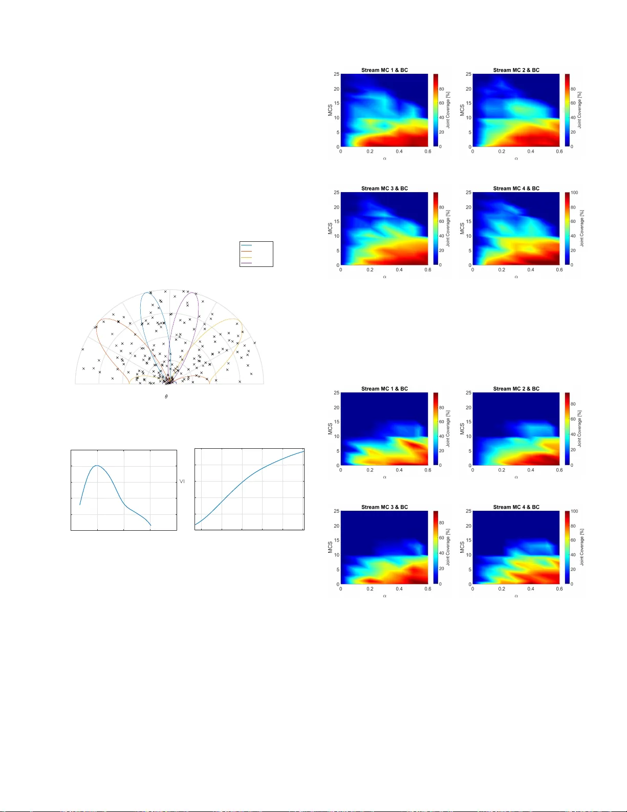
NOMA Assisted Joint Broadcast and Multicast T ransmission in 5G Networks Pol Henarejos, Mus bah Shaat and Monica Navarro Centre T ecnol ` ogic de T elecomunicacio ns de Catalunya (CTTC/C ERCA) Parc Mediterran i de la T ecn ologia, A v . Carl Friedrich Gauss 7 , 08860, Castelldefels, B arcelona, Sp ain. Phone: +34 93645 2900 , Fax: +34936 45290 1 Email: { pol. henarejos,m usbah.shaat,monica.nav arro } @cttc.es Abstract —In this p aper , we employ the n on-orthogonal mul- tiple access (NOMA) techniq ue to co n vey joint broadcast and multicast streams to a set of users. Thank s to the spatial beamf orming, different g roups of users is a ble to rec eiv e different streams in addition to the comm on broadcast inform ation. With the proposed scheme, the same time-frequency re sources can be shared between different streams, without requiring addit i onal bandwidth. The transmitter implementation is p resented a nd two recei ver c lasses are considere d based on S uccessiv e Interfer ence Cancellation (SIC) and Joint Decoding (JD) approaches. In addition to the performa nce assessment via simul ation, a real hardwar e proof of concept implementation of the proposed technique is perf ormed in order to show the practical viability of the pr oposed scheme. Key words — Broad cast,Multicast,NOMA, Non-orthogonal Infor- mation, 5G. I . I N T RO D U C T I O N Considering the emerging tren d in u ser behavior and de- mands for multimedia services, 5G networks are predicted to support many more users per cell than cu rrent deploymen t. Reliable integration of b roadcast and multicast services with the mobile br oadban d wireless n etworks can offer si gnificant benefits to different serv ices like: multimedia content deli very , file d istribution, software update s, emergency messages and public warning, etc. Current limitations of long term ev o- lution (L TE) e v olved multimedia bro adcast multicast serv ice (eMBMS), in having low Do ppler speed tolerance and in limiting cyclic prefix supported leng th, add more challenges in sup porting the users’ m obility and in increasing th e service coverage. Ad d itionally , eMBMS services do not fully exploit the spatial d imension. Non-or thogon al tr ansmission ap proach e s are being con - sidered as a promising so lution to m ultiplex different ser- vices under common physical lay er reso urces, increasin g net- work throug hput an d efficiency [1], [2]. In par ticular , no n- orthog onal multiple access (NOMA) is a promising mu ltiple- access scheme that exploits the differences in u ser channel quality (SNR) along with suitable power allocation and succes- si ve interfer ence c ancellation (SIC) at the recei ver in order to improve the system throu ghput [3]. I n fact, NOMA ap plies the well-known superpo sition coding solution fr om inf ormation theory , which achiev es the broadcast channel capacity for single antenna systems. Howe ver , the capacity and the capacity achieving transmission technique for the M IMO b roadcast channel are in general unkn own. When th e chan nel is fixed it is known th at dirty paper coding [4] achiev es c a p acity . Howe ver , ev en in this pa r ticular case the techn iq ue is far from being implemented in practice. Multicast beamform in g with superposition coding (SC) with two-stage beamform in g is ap plied to NOMA system to support mu ltip le users in [5], [6]. Th e same scheme is u sed to perfor m multiresolutio n broadcasting w h ere both high an d low priority data are tr a nsmitted in th e network. Laye r ed di vision multiplexing (LD M ) which is a form of NOMA is prop o sed in [7] to simu ltaneously using the same r e so urce bloc k for multiple unicast or for broadcast transmission assuming a single frequency n etwork (SFN). The applicatio n of NOM A to mu lti-user network with m ixed multicasting and unicasting traffic is con sidered in [8]. Th e beam forming and power allocation are design e d in order to ensu re an improvement in the unicasting perfor mance while maintain the rec eption reliability of m ulticasting. In this paper, we develop a n ovel system that is able to d eliv er multiple multimed ia streams sha r ing the same frequen cy-time reso urces by enabling non-orth ogona l trans- missions. Moreover, than ks to spatial be a mformin g, we a re able to secto rize such informatio n dy namically , allowing the coexistence of different multicast and broad cast streams de- voted to different grou p of users. Fin a lly , we also p rovide a demonstra tio n of its viability by a Proof o f Concept (Po C), where the proposed techniques are implemented in r eal de vices by m eans of Software Defined Radio (SDR). The rest of this paper is organ ized as follows: the system model is describe d in the sectio n II, where the transmitter scheme is analyzed; two different strategies of rec e p tion b ased on SIC an d J oint Decoding ( JD) a re introduced in section I II and IV , r espectively . Finally , the Po C is describe d in section V . I I . S Y S T E M M O D E L Giv en a MIMO system with N t and N r antennas at transmission and rece p tion, we aim at conve ying o n e broadcast stream inten ded to all user s in the system and N t multicast streams to dedicated users or to a dedicated cluster of users. Each multicast stream is co n veyed u sing an orthonorm al beam and a ll are superposed with the bro adcast stream by adju st- ing the p ower level by the par ameter α . W ith this scheme , N t orthog onal beams can be constructed and therefore 2 N t indepen d ent streams can b e conv eyed. Howev er , we also want to preserve the b r oadcast stream. Th is means that at least, o ne stream sh all be th e same for a ll o rthogo nal beams. Hence, ther e are N t + 1 a v ailable streams. The sup erposed sign al, which contains the contribution of the par ticular multicast stream in addition to the broadcast stream, is denoted as x k = √ α t k + √ 1 − α t BC , k = 1 ...N t , (1) where t k is the encod ed blo c k, i.e., t k = G ( u k ) using the encod ing function G ( · ) , t BC = G ( u BC ) is the enc o ded broadc a st c o dew ord, u k and u BC are the multicast and broa d- cast p ayloads, and α is the balancing p arameter between the multicast and br oadcast streams. Note th a t each symbol in u k [ n ] and x BC [ n ] is conve yed at n th tim e index. It is worth to men tion that each en coded block ca n be encod ed u sing different coding rates. The beam forming matrix B ∈ C N t × N t contains the beam- former s in each column. Th e channel matrix H ∈ C N r × N t is assumed as a rand om variable, with ar b itrary statistic. F or the particular m th user, th e r eceiv ed signal at the n th discrete time instant is y m [ n ] = H m [ n ] Bx [ n ] + w m [ n ] , (2) where y m [ n ] ∈ C N r is the received signal by the m th user , H m ∈ C N r × N t is the channel between the transmitter and user, x [ n ] = ( x 1 [ n ] · · · x N t [ n ] ) T is the tr a nsmitted vector , and w m ∈ C N r is the Additi ve Wh ite Gaussian Noise (A WGN). From now on, we assum e that the user m belon gs to the k th m ulticast g roup. I I I . B R O A D C A S T A N D M U LT I C A S T S I C D E C O D I N G The system mo d el can be envisaged as th e contribution of desired s ignals ( th e broadcast and in tended mu lticast stream), the inter ference of oth er multicast stre a ms and th e no ise. T hus, expanding (2), we can group the dif ferent con tributions as y m [ n ] = H m [ n ] √ α b k t k [ n ] | {z } Multicast Stream + √ 1 − α t BC [ n ] N t X k =1 b k | {z } Broadcast Stream + √ α N t X k ′ 6 = k b k ′ t k ′ [ n ] | {z } Inter-b eam Interference + w m [ n ] = H m [ n ] √ α b k t k [ n ] | {z } Multicast Stream + √ 1 − α B1 t BC [ n ] | {z } Broadcast Stream + √ α ˘ B k ˘ t k [ n ] | {z } Inter-b eam Interference + w m [ n ] , (3) where 1 is all-o nes vector , B = ( b 1 · · · b N t ) T , ˘ B k is the beamform in g m atrix witho ut the k th column and ˘ t k [ n ] = ( t 1 [ n ] · · · t N t [ n ] ) T \ t k [ n ] . T o estimate th e symbo ls t k [ n ] and t BC [ n ] , the Minimu m Mean Squar e Error (MMSE) estimator is em ployed with SIC. The g eneralized MM SE expr ession can b e summ arized as Definition 1 (MMSE): Given a linear process such that y = Ax + z , where A is a deterministic and k nown matrix, x is an unknown zero mean v ector and z is a ze ro mean u ncor- related rand om vector , th e MMSE estimation of x is defined as ˆ x = Wy where W = C xx A H C z z + A C xx A H − 1 . Dependin g on th e k nowledge of th e p recoding matr ix at receiver , i.e., wheth e r the user k nows the full B or k n ows b k , different math ematical f ormulatio n can be expr essed as i n th e sequel sub sections. A. Users with full form knowledge of B In this case, users only know the full form of matrix B . It correspond s to the scenario wh ere the beamfor ming matrix is static and offline-known by all the u sers or it is signaled to users in a semi-static basis. For the sake of clarity , we omit the n index. Based on MMSE definition, the parameters as follows x , t BC A , √ 1 − α H m B1 z , √ α H m Bt MC + w m C xx = 1 C z z = α H m B I E t MC t H MC B H H H m + σ 2 w m I = α N t H m H H m + σ 2 w m I , (4) where t MC = ( t 1 · · · t N t ) T contains the N t multicast sym- bols an d I E {·} is th e expectation operato r . T o estimate th e broadc a st symbo l, we consider multicast symbols as interfer- ence. Thus, the expression of the MMSE filter for the broadcast symbol has the follo wing expression W BC = √ 1 − α 1 H B H H H m α N t H m H H m + σ 2 w m I + (1 − α ) H m B11 H B H H H m − 1 . (5) According ly , the bro adcast symbol can be estimated as ˆ t BC = W BC y m (6) T o e stimate the multicast symbol, first we apply the SIC principle where th e estimated broa d cast symbol is subtracted from the received signal. Hence, ˘ y m = y m − √ 1 − α H m B1 ˆ t BC . (7) At this stag e, ˘ y m only contains the multicast symbo l plu s the interferen ce of o ther m ulticast sy mbols an d no ise. Hence, the MMSE definitions c a n be described as x , t k A , √ α H m b k z , √ α H m ˘ B k ˘ t k + w m C xx = 1 C z z = α H m ˘ B k I E t k t H k ˘ B H k H H m + σ 2 w m I = α H m ˘ B k ˘ B H k H H m + σ 2 w m I , (8) and the MMSE filter for the m u lticast symbo l is e xpressed as W MC = √ α b H k H H m σ 2 w m I + α H m ˘ B k ˘ B H k H H m + α H m b k b H k H H m − 1 = √ α b H k H H m σ 2 w m I + α N t H m H H m − 1 . (9) Finally , the multicast sym b ol can be estimated as ˆ t k = W MC ˘ y m . (10) Once ˆ t BC and ˆ t k are estimated , both are stacked to compose t BC and t k vectors, respectiv ely . Thu s, k th multicast payload and th e bro adcast o n e are decoded as ˆ u BC = G − 1 ( t BC ) ˆ u k = G − 1 ( t k ) , (11) where G − 1 is the in verse procedure of channel coding. The p roposed scheme accepts two refinements depe nding on 1 ) the feedback erro r correction mo tiv ated by the er ror correction pr o perty of the chan nel codin g , and 2) u sing a pre-equ alization stage to increase the co mpatibility of existing schemes. 1) W ith F eedback Err or Corr ectio n: On e of the advantages of using cod ed symbols is th e fact that the chan nel coding can correct errors. T o exploit this advantage, the receiver c a n stack first the estimated br o adcast symbo ls, decode a n d r e - encode them and finally s ubtract from the recei ved signal. In this c a se, ( 7) is replaced by ˘ y m = y m − √ 1 − α H m B1 ¯ t BC , (12) where ¯ t BC = G ( ˆ u BC ) is the re-encoded bro a d cast codeword. Finally , br oadcast an d multicast symbo ls ar e estima te d by using (6) a n d ( 1 0), where y m is rep laced b y ˘ y m giv en in (12). Alth o ugh this schem e exploits the c o rrection pro p erties of chann el coding, it increases the latency , since the receiver cannot perform parallel decoding of the multicast an d broad- cast sym bols. 2) W ith Pr e- Equalization : A possible app r oach is pre- equalizing th e chan nel matrix by an MM SE filter o r oth er standard equalizers o f the chann el matrix. That is equ i valent to: 1) e q ualize the channel m atrix, an d 2) equalize pr ecoding matrix an d sup erposed codewords. The pre-equalized received signal with a M M SE filter is de n oted as ¯ y m = σ 2 w m I + H H m H m − 1 H H m y m . (13) T o com pute the multicast and br oadcast symbo ls, we use (6) and (1 0) af ter replacing y m by ¯ y m giv en in (1 3). Note that pre-equ alization is compatible with Feedbac k Erro r Correction. Thus, (7) a n d (12) ca n also be u sed after r eplacing y m by ¯ y m giv en in (13). At th is stage, we assume that the chan n el contribution in (13) is compen sated and therefor e, the MM SE b roadcast and multicast filters can be com p uted by suppressing the channel contribution in (5) and (9). Thus, W BC = √ 1 − α 1 H B H α N t I + R ˜ w m + (1 − α ) B11 H B H − 1 W MC = √ α b H k R ˜ w m + α N t I − 1 , (14) where ˜ w m = σ 2 w m I + H H m H m − 1 H H m w m R ˜ w m = I E ˜ w m ˜ w H m = σ w m H H m H m σ 2 w m I + H H m H m − 2 . (15) On one side, alth ough this scheme simplifies the exp r es- sions, it propagates the error s p roduced by the pre-equalizatio n and colourizes the noise autoco r relation matrix. On th e other side, it increa ses the comp a tibility with the previous deploy- ments, since the recei ver can b e upgraded wit hout modifying the e x isting sign a l proc e ssing blocks. B. Users with beam weight knowledge This is th e case where the u sers on ly know their b eam weights. Users estimate bea m weig h ts based on pilots an d ar e not ab le to estimate th e adjacen t beam weights since they are almost ortho gonal to their chan nel. This corresp onds to the scenario where th e tran sm itter op timizes the preco ding matrix dynamica lly while the users have to estimate their respective beam weights. Since B is partially known (indeed , only b k is kn own), it means that ˘ B k is also un k nown a n d the expressions have to be rewritten b a sed on this con straint. Accordingly , we assume tha t the ch a nnel matches with the intended beam an d no t matches with the r est o f the b eams. In other words, we assume that k H m b k k≫ k H m b j k , k 6 = j. (16) This assumption approx imates (3) b y taking o nly the c o ntri- butions of b k into account. Hence, y m [ n ] ≈ H m [ n ] √ α b k t k [ n ] | {z } Multicast k th Stream + √ 1 − α b k t BC [ n ] | {z } Broadcast Stream + w m [ n ] (17) This is valid in th e case where the channel matches with the beam k and is orth ogona l with the rest. Hen ce, the bro adcast filter definitions become x , t BC A , √ 1 − α H m b k z , √ α H m b k t k + w m C xx = 1 C z z = α H m b k b H k H H m + σ 2 w m I . (18) Thus, the b roadcast MMSE filter is expre ssed as W BC = √ 1 − α b H k H H m σ 2 w m I + α H m b k b H k H H m +(1 − α ) H m b k b H k H H m − 1 = √ 1 − α b H k H H m σ 2 w m I + H m b k b H k H H m − 1 . (19) The subtracted received signal is obtain e d by rec onstructing by with the tran smitted sign al. Hence, ˘ y m = y m − α H m b k ¯ t BC (20) Finally , the multicast MMSE filter is expressed as W MC = √ α b H k H H m σ 2 w m I + α H m b k b H k H H m − 1 . (21) Pre-equalizatio n can also be ap p lied in this case, where ( 1 9) and ( 21) are reduced to W BC = √ 1 − α b H k R ˜ w m + b k b H k − 1 W MC = √ α b H k R ˜ w m + α b k b H k − 1 . (22) In summary , there are se veral possibilities and combin a- tions depending o n the knowledge of the beam f orming matrix , on the feedback err or correc tion and the pre-equ alization. In detail: • Users know B fully or partially: ◦ Pros: the accuracy p r oduces better results. ◦ Cons: increase the complexity a n d requires signalling of B . • Feedback correction is applied or n ot: ◦ Pros: reconstru cted signals are more pr ecise since some errors are c orrected. ◦ Cons: incre a se th e d elay since the mu lticast signal h a s to be deco ded initially . • Pre-equalizatio n is a pplied or not: ◦ Pros: incr ease the accur acy and simplify the expressions. It can be used with legacy chann el estimators an d equ alizers. ◦ Cons: propagates chann e l e stima tio n err ors. I V . J O I N T D E C O D I N G In the pr evious schem es, the SIC pr in ciple is applied where the broadcast symbol is decoded first, reconstructed, subtracted from the received signal and then, the m ulticast symbo l is estimated. SIC in volves the err or forwarding drawback, which means that if the broadc ast sy m bol is not decoded successfully , the multicast symbol will n ot. Fortun ately , (2) can be r ewritten with a joint m atrix n otation as y m [ n ] = H m [ n ] ( b k B1 ) √ α 0 0 √ 1 − α t k [ n ] t BC [ n ] + √ α ˘ B k ˘ t k [ n ] + w m [ n ] = H m [ n ] ¨ B k ∆ ¨ t k [ n ] + √ α ˘ B k ˘ t k [ n ] + w m [ n ] , (23) where ¨ B k = ( b k B1 ) , ∆ = √ α 0 0 √ 1 − α , and ¨ t k [ n ] = ( t k [ n ] t BC [ n ] ) T . W ith this notation, th e receiver o nly ap plies o ne MMSE filter at once. Thus, the jo int MMSE filter d efinitions ar e x , ¨ t k [ n ] A , H m ¨ B k ∆ z , √ α H m ˘ B k ˘ t k [ n ] + w m C xx = I C z z = α H m ˘ B k I E ˘ t k ˘ t H k ˘ B H k H H m + σ 2 w m I = α H m ˘ B k ˘ B H k H H m + σ 2 w m I , (24) and th us, the joint MMSE filter is expressed as W J = ∆ ¨ B H k H H m σ 2 w m I + α H m ˘ B k ˘ B H k H H m + H m ¨ B k ∆ 2 ¨ B H k H H m − 1 . (25) Therefo re, th e jo int pay load ¨ t k is estimated by ¨ t k = W J y m . (26) Finally , in the case where pre- equalization is perfo rmed, (25) is reduced to W J = ∆ ¨ B H k R ˜ w m + α ˘ B k ˘ B H k + ¨ B k ∆ 2 ¨ B H k − 1 . (27) V . R E S U LT S In this section we describe the results obtained with joint broadc a st and multicast tr a nsmissions. W e simu late a scenario with a single base statio n and se veral user equipme nt placed at different positions within the cell. Modulation and Coding Schemes (MCS) and f raming is th e same as u sed in L TE. The simulation parameters are summarized in T a b le I . T ABLE I. C O M M O N R A D I O P A R A M E T E R S Bandwidt h 5 MHz Resource Blocks 25 Occupied Resource Elements 100 % Antennas at Bas e Station 4 Height of BS 15 meters Power 50 dBm Antennas at Us er Equipment 4 Number of users 100 Carrier Frequency 1 . 9 GHz Cell Radius 500 m Coding Rate 1 / 3 Antenna Correlation Low Path Loss Model Macro cell urban area [TS 36.942] N 0 − 174 dBm/Hz Noise Figure 7 dB Channel Model ITU Pedestrian B Max. Doppler Frequency 0 Hz Outage Probability 10 − 2 W e analyze the coverage using SIC and JD approaches. T o ev aluate the p erforman ce o f the propo sed schemes, we employ the coverage and joint coverage metrics. The cov e r age m etric is defined as Coverage ( k ) = 1 − N ′ ( k ) N ( k ) , (28) where k corr esponds to th e index of the stream, N ′ ( k ) are the numb er of users in outage (PER > 0 . 01 ), and N ( k ) is the total number of users served by stream k . The joint coverage metric comb ines the coverage of multicast stream k and the broadc a st stream, ensurin g that b oth achieve at lea st the same coverage individually . For example, a jo int coverage of 98% ensures that the multicast and bro a dcast s treams are received with a coverage o f 98 % each. In the considered scenario, th e users are pla c ed randomly in a cell with d ifferent distances. The path loss is d ifferent for each user and also its Signal to Noise Ratio (SNR). Fig. 1 illustrates the users across the cell an d the beam patter n used to conv ey th e multicast streams jointly with the br oadcast stream. Note that ea c h group k c on veys the k th multicast stream and the br oadcast stream. Fig. 2a and Fig. 2b depic t th e PDF and CDF of th e SNR distribution in this scenario , respectively . From the SNR distribution, we can ap preciate that the a verag e SNR v alue is 10 dB, with a maximum value of 30 dB and a minimum value of 4 dB. Radius [km] [º] 0.5 1 1.5 2 30 60 90 270 300 330 0 Group #1 Group #2 Group #3 Group #4 Fig. 1. Distrib ution of user and beam pattern. 0 10 20 30 40 SNR [dB] 0.01 0.02 0.03 0.04 0.05 0.06 p(SNR) (a) PDF 5 10 15 20 25 30 SNR [dB] 0 0.2 0.4 0.6 0.8 1 p(SNR) X (b) CDF Fig. 2. Probabili ty and Cumulati ve Density Func tions of SNR. A. F irst App r oach: SIC Receiver The transmitter implements the SIC princip le, with feed - back error corre c tion –sy m bols are d ecoded, re-enco ded and subtracted– , ledge of B , and pre-equ alization of the channel matrix. Fig. 3 illustrates th e joint coverage m etric (in % ) of each group as a fu nction of M CS and α . It is clea r that the maximum joint coverag e is achieved for low M CS and fo r an α in the vicinity o f 0 . 5 . B. Sec ond App r oach: Joint Decoding Receiver This receiv er imp lements the JD strategy , with also pre- equalization s tage. Fig. 4 depicts the joint coverage metric of each g roup as a function of MCS and α . As in the previous (a) Group 1 (b) Group 2 (c) Group 3 (d) Group 4 Fig. 3. Joint Coverag e for the SIC Rece i ver . scheme, the maximum join t c overag e is achie ved for low MCS and for an α in the vicinity of 0 . 5 . Ho wever , the c overage is reduced when it is compa r ed with SIC sch eme. (a) Group 1 (b) Group 2 (c) Group 3 (d) Group 4 Fig. 4. Joint Coverag e for the SIC Rece i ver . V I . I M P L E M E N TA T I O N A N D P RO O F O F C O N C E P T In this section we describe the implementation o f the Proof o f Concep t (PoC) o f Joint Broadcast and Multicast Communica tio ns. Particularly , we d emonstrate th e viab ility of the JD rec ei ver . For this PoC we u se 3 Universal Serial Radio Peripherals ( USRP) co nnected to a Gener al Purpose Processing Unit (GPPU). U SRP process the d igital samples gener ated by the GPPU according the fram ework that we d escribe in the previous sections, co n vert the d igital signal to/from analog domain and up(down)conv er t the analog signal to/from the RF band. In th is Po C on e USRP is configur ed as eNB and oth er two USRP as UEs. All USRP ar e c onnected to the GPPU via 1 Gigabit Ethernet. All USRP are c o nfigured with the same parameter s. The cell search stage is per formed by using a single carrier frequency , off-line configured . Althou gh th e carrier fre q uency is pr e-configu red in this setup, UEs shall to synchronize at subframe level. It imp lies that UEs h av e to use the synchron ization signals provided by L TE stand ard to determine the T ime Advance (T A). Once this synchronizatio n is stablished, UEs hav e to search the Master Information Block, which car ries info rmation about the ban dwidth and the number o f antennas at eNB. All configuration par a meters are estimated b y the UEs, except the carrier f requency and the sampling rate. T able II de scr ibes the main configuration parameters u sed for the demo. T ABLE II. C O M M O N R A D I O P A R A M E T E R S Frame T ype FDD Prefix T ype Normal Carrier frequency 915 MHz Bandwidt h 5 MHz Sampling frequency rate 7 . 68 MS/s Number of s ubcarriers 300 Control Channel width 3 symbols Coding Rate B C 0 . 3 Constellation BC QPS K Coding Rate MC1 0 . 43 Constellation MC1 QPSK Coding Rate MC2 0 . 43 Constellation MC2 QPSK Fig. 5 contains pictur e s taken from the PoC where tran s- mitter an d receivers are working in real time during the sho t. It is importan t to remark that each receiver decod es th e common broadc a st video (the same f or both receivers) as well as th e intended m ulticast video (different for each receiver). In this PoC, 5 MHz of ban dwidth are shared b y the three v ideos simultaneou sly . Constellations r eveal which is the impact of superp osing streams. Altho ugh all streams are co n veyed using a QPSK constellation, th e superp osing introdu c es cross in terferenc e s between the streams and th e constellation contain s more points compare d with the single case. Hence, the receiver has to cancel th is interference and r ecover b oth strea ms. It is shown that the schem e is applicab le and the dem o perform ance is satisfactory . (a) eNB (b) UE Fig. 5. General overvie w from eNB and UE sides. V I I . C O N C L U S I O N S In this paper, we considered the joint broad cast an d mul- ticast streaming by allowing n on-orth ogona l and sup erposed transmissions. W e first introdu c e th e tran smission scheme, which thanks to beamformin g it is possible to tran smit different multicast stream s separated by sp atial r egio n s in additio n to a comm on super p osed b roadcast stream, which is received by all u ser s. Different receiving strategies are also tackled. In p articular, SIC receiver is employed to redu ce the in ter- beam interf erence. A novel Jo in t Decod e r scheme is intro- duced, which dec o des the intended symbols withou t recur sio n. Finally , we built a Proof of Con cept of the p roposed techniqu e, demonstra tin g its viability . W e remar k that thanks to the pro- posed tech nique, different multimed ia services can be d eliv er ed without req u iring additional b andwidth nor mu ltip lexing in time slots. Sharing the same freq uency-resou rces and allo win g different Quality of Service (QoS) enhances the flexibility and efficiency of the system compared with traditional d eployments such as L TE. A C K N O W L E D G M E N T This work is supp orted by th e Ho rizon 202 0 pr o ject F ANT ASTIC-5G (ICT -671 660), which is partly fu nded by the Europ e a n Union, and also supported by the Spanish Govern- ment u nder project E LISA (TE C2014-5 9255- C3-1-R). R E F E R E N C E S [1] L. Dai, B. W an g, Y . Y uan, S. H a n , C. l. I, and Z. W ang, “Non-or thogon al mu ltiple access fo r 5G: Solution s, chal- lenges, o pportu nities, and f uture researc h trends, ” IEE E Communicatio n s Magazine , vol. 53, no. 9 , pp. 74–8 1, Sep. 2 0 15. [2] Z. Ding, Y . Liu, J. Choi, Q. Sun, M. Elkashlan, C. L. I, and H. V . Poor, “App lica tio n of n on-or th ogona l multiple access in L TE and 5G networks, ” IEE E Communications Magazine , vol. 5 5, n o . 2, pp. 18 5 –191, Feb . 20 17. [3] N. Nonaka, Y . Kishiyama, and K. Higuchi, “Non- orthog onal multiple access using intra-beam superposi- tion codin g and SIC in base station coopera tive mimo cellular d ownlink, ” in 2014 IEEE 80th V ehicular T ec h- nology Conference (VTC2014 -F all) , Sep. 2014, pp. 1 –5. [4] G. Caire and S. Shamai, “On the achiev ab le th rough put of a mu ltiantenna gaussian broad c ast channel, ” IEE E T ransaction s o n In fo rmation Th eory , vol. 49 , no . 7, pp. 1691–1706 , Jul. 2 003. [5] J. Cho i, “Minimum power multicast b eamform in g with superpo sition cod ing for multireso lution bro adcast an d application to NOMA systems, ” IEEE T ransaction s on Communicatio n s , vol. 63, no. 3, pp. 7 91–8 0 0, Mar . 20 15. [6] D. Darsena, G. Gelli, and F . V e r de, “An opp ortunistic spectrum access scheme f o r multicarrier co gnitive sen - sor network s, ” IEEE S ensors Journal , vol. 1 7, no. 8 , pp. 2596–2606 , 2017. [7] J. Zhao , O. Sim eone, D. Gundu z, and D. Go mez- Barquero, “Non -orthog onal unicast and broad cast trans- mission via joint beamf orming an d LDM in cellular networks, ” in IEEE Global C ommunica tions Conference (GLOBECOM) , De c . 2 016, p p. 1–6. [8] Z. Din g , Z. Zha o , M. Peng, and H. V . Poor, “On the spectral e fficienc y a n d secu rity en hanceme n ts of NOMA assisted multicast-un icast streaming, ” IEEE T ransactions on Com m u nications , vol. PP, no. 9 9, p p. 1– 1, 201 7.
Original Paper
Loading high-quality paper...
Comments & Academic Discussion
Loading comments...
Leave a Comment