Advanced Signal Processing Techniques for Fixed and Mobile Satellite Communications
Enabling ultra fast systems has been widely investigated during recent decades. Although polarization has been deployed from the beginning in satellite communications, nowadays it is being exploited to increase the throughput of satellite links. More…
Authors: Pol Henarejos, Ana Perez-Neira, Nicol`o Mazzali
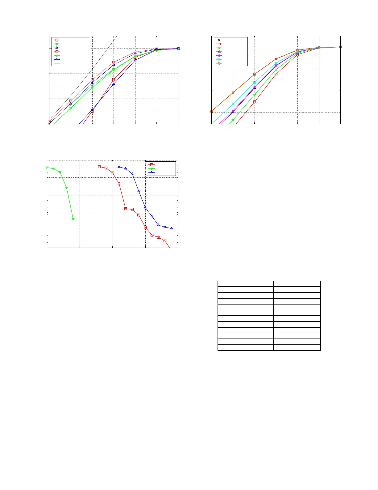
Adv anced Signal Processing T echniques for Fix ed and Mobile Satellite Commu n icati o ns Pol Henarejos ∗ , Ana P ´ erez Neira ∗ , Nicol ` o Mazzali † , Carlos Mosquera ‡ ∗ Centre T ecnol ` ogic de T elecomun icacions de C atalu nya 08860 Castelldefels, Barcelona, Spain Email: { pol.he narejos, ana.perez } @cttc.es † Interdisciplin ary C en tre for Security , Reliability and T r ust (SnT), University of Luxembou rg Email: nicolo.ma z zali@uni.lu ‡ Signal Theory and Comm u nications Dep artment, University of V igo , 36310 V ig o, Spain Email: mosquera @gts.u vigo.es Abstract —Enabling ultra fast systems h as been widely inv esti- gated d uring recent decades. Alth ou gh polarization is deployed from the beginning in satellite communications, nowadays it is being exploited for increasing the throughput of satellite links. More precisely , the irruption of multiple-in p ut multiple-output (MIMO) technologies combined with p olarization domain is a promising topic to p rovide reliable, robust and fast satellite communications. Better and more flexible spectrum use is also possible if transmission and reception can take place simultane- ously in close o r eve n overlapping frequency bands. In this paper we inv estigate nov el signal processing techniq ues to increase the th roughput of satellite communications in fixed and mobile scenarios. First, we analyse and inv estigate 4D constellations for the f orward link. Second, we foc u s on the mobile scenario an d introduce an adaptiv e algorithm which selects the optimal tuple of modulation order , codin g rate and MIMO scheme that maximizes the throughput constraint to a maximum packet err or rate. Finally , we describe th e operation of radio t ransceiv ers which cancel actively the self-interference posed by the transmit signal when operating in ful l-duplex mode. Index T erms —Satellite Communications, Polarization, Full Duplex, 4D Constellation s, Mu ltimedia Communications I . I N T RO D U C T I O N In recent years, the increa sin g dem and of higher data rate commun ications has mo tiv ated many resear c hers to focus their effort on the investi g ation of diversity techn iques, such as massi ve multiple-input multiple-ou tput (MIMO) systems [1] a nd space - time codes ( STC) [2]. Howe ver, both these technique s do not fit well the satellite scena r io: the spatial richness req uired by MI MO systems can not be provided b y fixed satellite links [3], and the delay caused b y STCs is not acceptable in systems having time con straints. Nevertheless, polarization diversity has been con sidered as a viable option in S-band applicatio n s [ ? ], [4]. The sign al processing described in these works is perfo r med after the mod u lation, making it agnostic to the ado pted constellation. On th e contrar y , sev e r al resu lts on con stellation design can be fou nd in the terrestrial MIMO literatur e , e.g., in [5] and r e ferences therein . I n most of these work s, the ad opted perfor mance metric is th e p airwise er ror pro bability and th e union boun d. In the first part of th e paper , we focus on assess in g the perfor mance o f constellation s for d ual-polar (DP) satellite systems serving fixed users. In p articular, we in vestigate fo ur- dimensiona l (4 D) constellation s, wh ere the number of dimen- sions is giv en b y the total number o f co mpone n ts (in-p h ase and quadr ature) over th e two polarization s. Mor eover , a joint processing of the two streams is considered at the receiver as in a traditional du al-polar MIMO scheme. Unlike the cited works on co nstellation design in MIMO systems, we choo se as main perfor mance metrics the a chiev able in f ormation rate (AI R) and the pragmatic achie vable information r a te (P AIR). The P AIR allows for a join t evaluation o f th e perfor m ance of the constellation symbols and their labels, which is of paramount importan ce in practical scena rios (i.e., where chann el coding is used). Ind e e d, m ost of the recent works on 4D constellations assess the performance in terms of sy mbol erro r rate o r in uncod e d sy stems [6], n eglecting to take into acc ount the impact of the labe llin g d esign. In gener al, multidimensional constellations show b etter per- forman ce than 2 D co nstellations [7]. For example, QAM con - stellations over A WGN chan nel suffer from a loss with r espect to the capacity of 1 .53 dB. This sh a p ing loss can b e pa r tially compen sated by using a 4D con stellation based o n lattices. Indeed , th e asympto tic shaping gain pr ovided by a 4D lattice- based de sig n is only 0.46 d B [7]. The den sest lattice in 4D is known, and its character istics have been thor oughly studied in [8]. Ne verth eless, dense lattice- based constellation s may perfor m poo rly in p r actical systems because they maxim iz e only the minim um E uclidean distance between sym bols, which is a good d esign criterion only at high signal-to-n oise ratios (SNRs). In th e following we co mpare the pe rforman ce in terms of P AIR of 4D constellations ov e r the A WGN channel. In particular, we will con sider lattice-based con stellations ( also called lattice amplitu d e mod ulation, LAM) , enhan ced po lypo- larization mo d ulation (EPPM, as descr ibed in [6]), and con - stellations generated by means of the Cartesian product of two standard 2D constellations, denoted as as √ M × √ M -QAM. The last approach is eq uiv alent to tran smitting ind e pendently over th e two po larizations or performing spatial mu ltiplexing [3]. In the seco nd part o f the pap er , we stud y the viability of DP in mo bile scenarios. Althou gh DP has b e en used fo r many decad es in fixed satellite comm unications, the polariza- tion mu ltiplexing was perfo rmed without any a d aptation no r flexibility and DP was not receiv ed simultaneo usly . Howe ver , it has been proven that DP can also be ap plied to mob ile satellite co mmunica tio ns. In this way , DP may be emp loyed to inc rease the system cap acity to increase th e throug hput o f the individual link s and in crease th e num b er of User T erminals (UE) connected to the network by taking th e advantage of the partial d ecorrelation of the two polarization s. This approa c h is mo delled using MIMO notation and it c a n be exploited by MIMO signal proc essing tech niques. The first challenge of DP is to provide a new commun ica- tion system wh ere the inf o rmation can be modu lated on th e polarization state of the w aveform and satis f y the scenario constraints. T o achieve it, the terminals are able to ad apt to the satellite chann el and feedback to the ground gateway which modulatio n and codin g schem e is th e b est for the session as well as which polar ization MIMO scheme should be used. The second ch allenge is to implemen t the pro posed a lg o- rithms in realistic scenarios. T o f ulfil it, we aim to dep loy an adaptive algo rithm and use the Broadband Global Area Network (BGAN) standard , specified in [9], as a ben chmark . This standar d describ es pr ocedure s which p rovide m u ltimedia mobile satellite com m unications with low laten cy and high flexibility in terms of th roughp ut. D u e to the lon g and slow shadowing, it is necessary to impleme nt the p hysical layer abstraction (PLA) of the proposed scheme. Thus, the PLA is a tool to model the PHY , o btain these parameters that are in volved in the a d aptation of the link an d estimate the err or rate, without to ru n th e whole codin g an d decoding chain. W ithin the fram ew ork of the SatNEx consortium special attention has been also pu t on the co m parison between fu ll- duplex and half-d uplex operation in the satellite fo r the op e r a- tion of the new VHF Data Ex change System (VDES) standard [10]. Fu ll Duplex (FD) represents an attractive solution to improve the th rough p ut o f wireless comm unications. The term FD is historically u sed to refer to tho se system s th a t transmit and receive simultaneou sly , like Freq u ency-Division Duplexing (FDD). If tran smission and reception take place in the same fr e quency band, then In-Band Fu ll Dup lex (IBFD) is th e right term . W e will present some initial considerations on the coexistence of simultaneou s transmission and reception when leakage from the tran smitter affects the recei ver; some cancellation techniques are commo n also to novel I BFD, which have spurred a lo t of a cti v ity in th e last f ew years [11], [12]. ENC MOD PROJ DET DEMAP DEC b n x k x k,H x k,V w k,H w k,V y k,H y k,V ˆ P ( x k | y k ) L n Fig. 1. System model for the performanc e assessment of 4D constellati ons. I I . P E R F O R M A N C E A S S E S S M E N T O F 4 D C O N S T E L L AT I O N S In the following, we d escribe the system model assumed for the perf o rmance assessment, as well a s the cho sen p er- forman ce metric. Finally , we p rovide some details about the in vestigated constellations. A. System Model The co nsidered system model is depic te d in Fig. 1. The informa tio n symbols { x k } belong to a 4D constellation χ having M = 2 m symbols, which are ass o ciated to the b its { b n } throu gh the labeling µ : χ → { 0 , 1 } m . W e den ote by µ i ( x k ) the value of the i - th bit of the la b el mappe d to symbol x k . Since the transmission on the ph ysical chan nel is separate fo r each p olarization, the selected 4 D symbol x k has to be pr o jected o n to two o r thogon al 2 D p lanes. Th is operation generates two 2D symbols, x k,RH and x k,LH , wh ich are to be transmitted over the right-hand (RH) and left-hand (LH) side circular polarization s, resp ectiv ely . In the following, we assume the infor mation symbols { x k } to be indep endent and uniform ly d istributed r andom variables. Depending on the chosen 4D constellation χ , the projected symbols x k,RH and x k,LH may b e co r related and have a non -unifo rm pr obabil- ity distribution [13]. In deed, if the 4D constellation is n ot obtained as the Cartesian produ ct of two 2D constellation s, then the projection onto a 2D plan e may in duce a shaping in the projected 2D constellation s. W e deno te by x k the 4D transmitted symbol a t time k , and by x k = [ x k,RH , x k,LH ] T the cor respondin g vector containin g the 2D p rojected symbols transmitted on the two polarizatio ns at time k . Hence, the received symbo l r eads y k = [ y k,RH , y k,LH ] T = x k + w k where w k = [ w k,RH , w k,LH ] T denotes the samples of the A WGN process intro duced by the chan nel. On each po lar- ization, we assume the ad d iti ve noise compo n ent w k,c to be a circularly -symmetric com plex Gaussian rando m variable with mean zero and variance σ 2 per compon ent, wh ere c identifies th e two polariza tio ns. Since the p ossible co rrelation between x k,RH and x k,LH may ca u se a p erforman ce lo ss if the de tection is per formed separately o n each po larization, only joint d etection will be con sidered. The cho sen detection strategy is the soft maximum likelihood, pr oviding as outpu t of th e d etector, a t every time k , the set of M a posterior i probab ilities { P ( x k | y k ) } [14]. B. Pragmatic Achievable Information Rate In o r der to assess the co n stellation perfo rmance, the ch osen metric is the P AIR [ ? ], defined as I p ( χ, µ ) = 1 M m X i =1 X x ∈ χ E w log P ( y | µ i ( x )) P ( y ) (1) where th e expectation is taken with respect to the A WGN dis- tribution. Since a closed-form expression for th e expectation in (1) is no t av ailable, nu merical method s are usually employed for its ev aluatio n . C. 4D Constellation Design s In the following, the two classes of 4 D co nstellations are described and their main features ou tlined. 1) Cartesian Constellations: The simplest way to obtain a M -ar y 4D constellation is by taking the Cartesian pro duct of two 2D constellation s (e.g ., √ M -QAM) , c a lled c onstituent constellations [13]. Since √ M × √ M -QAM ar e equiv alent to MIMO with spatial mu ltiplexing, they will be used in the following as per f ormance benchmark. It is w o rth noting that the projectio n is n ot necessary in DP system s using Cartesian- based 4 D co nstellations. In deed, since the p r ojection can b e viewed as the in verse of the Cartesian produ ct, the projected constellations coincid e with the co nstituent constellations. For √ M × √ M -QAM, the map ping h a s been obtained by ap plying the Gray mappin g separately on the two 2D constituent constellations. 2) Non-Cartesian Constellation s: The rema ining types of constellations considered in this p aper , i.e., L A M an d EPPM, belong to this class. Sin ce the constru ction of EPPM is detailed in [6], it is no t re ported here. The adop ted map p ing h as been o btained nu merically by u sing an instance o f the gen eric algorithm aiming at ma x imizing th e P AIR. The densest lattice in 4D is the c e ntered cubic lattice D 4 , the so-called checkerbo a rd [8]. Being the d ensest lattice in 4 D, it provides the best coding gain by max imizing th e min imum Euclidean distance between the co nstellation symbols [8]. In order to get a M -LAM, only M points of th e lattice are selected. The selection is done b y ch oosing the points closest to the origin, i.e., the ones with the lowest energy . This is equiv alen t to perf orm a cut of the lattice with a centered sphere an d selectin g th e lattice poin ts inside the sphere. Such a s p herical cut induces a shaping gain in the projected 2D constellations. If the spherical cut selects more than M points, it means that many M -ary constellations with different av er a ge energies exist. Th en, an in stan ce o f the gen etic algor ithm is applied ov e r th e set of possible con stellations with the lowest energy in order to find the one with the h ighest AIR. For M - LAM, because of the hig h numbe r of neigh boring points [8], n o G r ay mapping exists. Moreover , for some values of M it is possible to construct a quasi-Gray m apping (QG) of order 2 or 3 (where QG( n ) deno tes a m apping where the labels of neigh boring symbols differ f or at mo st n bits), but in gen eral the co rrespond ing per f ormance is worse than that obtained with a n u merically o ptimized mapping . I I I . A D A P T I V E M I M O S C H E M E , M O D U L AT I O N O R D E R A N D C O D I N G R A T E I N D U A L P O L A R I Z E D I N S A T E L L I T E C O M M U N I C AT I O N S A. Physical Layer Ab straction The g o al o f PLA is to obtain the instantane ous erro r rate in order to estimate th e instantan e o us of capacity as a function of the r adio ch a nnel coe fficients. Henc e , it is p ossible to run the simulations where the channel fading may not be corr elated in time and therefore sp eed up th e time of simulation. T h e m odel takes the mod u lation scheme, the co ding rate, polar ization scheme an d many other param eters to adju st the bit load ing depend ing on the magn itudes of the radio channel. PLA also offers the chance to stud y and analyse th e impact of th e feedback carried by UE. Since the conve y ed symbols are conv o luted by the chan- nel, each symbol experimen ts a different channel fadin g and therefor e the Signal to Interf e r ence plu s No ise Ratio (SI NR) is different b etween the symbols in the same block. Thus, a metric of effecti ve SINR is need e d. This metric maps the equiv alen t SINR of the transmitted blo ck to the erro r r ate an d it is called effecti ve SINR mappin g (ESM). Hence, th e ESM is defined as a function to obtain the error rate from a single v alue that rep resents the ef fective SINR. From [15], the effecti ve SINR is mathematically defined as ¯ γ = β 1 φ − 1 1 N N X n φ γ n β 2 ! (2) where γ is the N -length vector o f the SINR of each symb o l and β 1 , β 2 are parameters to a d just the accuracy of th e approx imation. Th e fu nction φ ( . ) defines th e appro ach o f ESM. In some cases, the rep resentation of the err or curves does not con tain an analy tical expression or becomes too complex. Thus, different a p proach e s are pr oposed in the literature. In th is pap er , we use Mutu al Info rmation Effecti ve SINR Mapping (MIESM) since it takes the function o f th e cap acity of the link and estimates the equ i valent SINR. It is expr essed as φ ( x ) = I E X Y log 2 P ( Y | X , x ) P X ′ P ( X ′ ) P ( Y | X ′ , x ) (3) where X is the tran smitted symb ol, Y is the re c ei ved sym b ol and I E { . } is the expected value. Assumin g that a symb ol is transmitted with a M -ar y constellation, (3) can be expressed as φ ( y ) = log 2 M − 1 M X x ∈ X I E w ( log 2 X x ′ ∈ X e − | x − x ′ + w | 2 −| w | 2 σ 2 ) (4) where X is th e set of the constellation an d w ∼ C N (0 , σ 2 ) and σ 2 = 1 /γ . This expression c an be com puted offline via Montecar lo simulations generating different realizations of the random variable. Ne vertheless, in [16] different results are exposed by QPSK, 16 QAM and 64 QAM, fo r a ran g e of − 20 : 0 . 5 : 2 7 d B of SINR. Although ther e is not a closed expression, it is possible to compute this expression for different values and store the results in a look up table (LUT) to find the values of φ − 1 ( x ) [17]. B. Physical Layer Ab straction an d MIMO In the pre v ious section we described the PLA for the Single- Input Single- Output ( SISO) and Single-I n put Mu ltiple-Output (SIMO) scen arios. In the case, the perfo rmance of th e pre v ious abstraction d epends on the imp lementation of the receiver . In [16] pro pose two app roaches dependin g on the receiver: • Line a r M I MO Receivers. Th e use of linear r eceiv er s allows low com putational co mplexity implemen tations and offers th e chanc e to suppress or mitigate the cro ss interferen ce o f th e inputs. T hus, witho ut loss of general- ity , the receiv er can decouple both po larizations into two separate stream s. Hence, the mapp ing is p erforme d using the SISO/SIMO appr o aches. • Max im um Likelihood (ML) Receivers. In this ap- proach , (4) is rewritten as a fun ction of the pr o bability of log-likeliho o d ratio (LLR). Howe ver , this ap p roach re- quires much mor e co mputation a l co mplexity and requires additional LUTs, which enlarges the required memo ry . For a given n th symbol, the system m odel of t inpu ts and r outputs MIMO scenario is d e scribed as y n = H n x n + w n (5) H = ( h 1 h 2 ) = h 11 h 12 h 21 h 22 (6) where y ∈ C r is the recei ved v e c to r , H ∈ C r × t is the random channel matrix, x ∈ C t is the transmitted vector and w ∼ C N 0 , σ 2 w I r is th e additive white Gaussian noise (A WGN). In order to g uarantee a feasible implemen tation, we use the linear MIMO receivers app roach. MIESM for linear r e ceiv ers is described by th e SINR expression depending on the MIMO scheme: • SISO: a single polar ization is used. Thus, the system model is expr essed as y n = h n x n + w n and therefor e γ n = | h n | 2 /σ 2 w . • Orth o gonal Polar ization T ime Block Codes (OPTBC): adaptation of the Ortho g onal Space T im e Block Codes, introdu c ed in [18], re placing the spatial componen t b y the polarization compon ent. The Since the OPTBC scheme exploits the full di versity of th e channel [19], the SINR can be expre ssed as γ n = k H n k 2 /σ 2 w , where k H n k 2 is the Frobeniu s nor m. • Polariz a tio n Mu ltip lexing ( PM): each po la r ization con - veys a symbol an d thus, two sym bols are transmitted in each cha n nel access. Assuming that the receiver is able to cancel the interfere n ce between both stream s, we obtain two equivalent SINR f o r each symb ol of each polarization [19], [2 0]. Hence, it is eq uiv alent to the previous section (th e SISO case) but with 2 N symbols rather than N . Therefor e, the equivalent SIN R of the m th po larization using the Zer o Forcer (ZF) r eceiv er is expressed as γ n,m = h H n,m h n,m /σ 2 w • Polariz e d Modulation ( PM): a single symb ol is tr ansmit- ted using a single polarization but the index of the used polarization is also a plac e f or con veying bits. In the case where two po larizations ar e used , PMod conve y s M + 1 bits ( M b its of th e symbol and a n additiona l bit o f the polarization state index) [2 1], [22]. Since a single symbol is transmitted, th e received SINR is equ ivalent to SISO expression. C. Physical Layer Abstraction and BGAN After the in troductio n o f the PLA for MIMO scheme s, we aim to im plement it to the BGAN standard. T his standard d e- scribes dif feren t modulation and coding schemes (MODCOD), with d ifferent modulation sch emes and different coding rates called bea r ers. Each bearer d efines a MOD COD, which h as different bit rate. From this standard , we g et that th e length of the block , N , can be 640 , 1 098 or 941 ; and the constellation size M can b e 2 , 4 , 5 or 6 . It is imp ortant to r e m ark tha t since each MIMO scheme produces a d ifferent SINR, for the same ch annel realization each MIMO scheme will produce a different er ror curve. Said that, we can form u late the objectiv e problem as max u m,d,c X m ∈M X d ∈D X c ∈C u m,d,c r m,d,c ( ¯ γ ) (7) s.t.P E R ( ¯ γ ) ≤ 10 − 3 (8) X m ∈M X d ∈D X c ∈C u m,d,c = 1 (9) where M is th e set o f MIMO modes, D is th e set o f modulatio n orde r s a n d C is th e set o f a vailable coding rates, r m,d,c ( ¯ γ ) is the achievable rate given the effectiv e SNR ¯ γ and the tuple m, d, c . In th is pap e r, we constrain t the PER less or equal to 10 − 3 . I V . N U M E R I C A L R E S U LT S In this section we pr esent the numerical results obtain ed in the different scena r ios. A. 4D Constellations in Fi x e d Scenarios For lack of space, we report the results obtained for M = 64 only . Fig . 2 shows th e perfor mance of 8 × 8 -QAM, 64-LAM, and 64-EPPM in terms of AIR and P AIR. Conce rning the AIR, 64- LAM and 6 4-EPPM o utperfo r m 8 × 8 -QA M , showing gains stemming from the shaping of the co rrespond ing 2D projected constellations caused by their non-Cartesian nature. Howe ver , when th e mappin g is ap plied (Gra y f or 8 × 8 - QAM, numerically o ptimized for 64 -LAM an d 64 -EPPM), non-Cartesian constellation s show an im pressiv e loss with respect to th eir AI Rs ( around 2 dB at 5 bits/ch.u se). These results are validated by the bit error rate (BER) curves shown in Fig. 3, whe r e a LDPC code with rate 5 / 6 has been used. The er ror floors in the curves r elativ e to 64 - LAM an d 64- EPPM testify that the chosen c o de is n ot suitable f or these non-Cartesian constellations. Better results can be obtain ed by using nu m erically optimized con stellatio n s over the A WGN channel [ 23], or by considerin g fading c h annels, wher e the robustness stemming from th e correlation b etween th e po lar- izations introdu ced by the shaping c a n be exploited [ 24]. 3 3.5 4 4.5 5 5.5 6 6.5 6 8 10 12 14 16 18 Pragmatic AIR [bit/ch.use] E s /N 0 [dB] 64-LAM opt 8x8-QAM Gray 64-EPPM opt 64-LAM AIR 8x8-QAM AIR 64-EPPM AIR 4D capacity Fig. 2. AIR and P AIR for 64-ary 4D constella tions. 10 -6 10 -5 10 -4 10 -3 10 -2 10 -1 11.5 12 12.5 13 13.5 BER E s /N 0 [dB] 64-LAM 8x8-QAM 64-EPPM Fig. 3. BER for 64-ary 4D constell ations. Since the main respon sible for the losses for LAM and EPPM is the bin ary mappin g, we h av e tested n on-bin ary mapping s for 64-LAM. In p articular, we have n umerically op- timized non-bina r y map pings over GF( 2 n ) with n = 2 , . . . , 6 , where GF( q ) d e notes the Galois field of order q . For each value of n , the map ping has b een optimized b y using the genetic algorithm to max imize the P AIR. Since n > 1 , in non-bin ary mapping s each label is fo rmed by ⌈ lo g 2 n M ⌉ digits belongin g to GF( 2 n ), where ⌈ x ⌉ denotes th e closest integer hig her than x . The results reporte d in Fig. 4 sh ow that incr e a sing the order of the Galois field is beneficial, making th e P AIR curve gettin g closer to the AIR curve. Moreover, when n = 6 , P AIR a nd AIR coincid e. This is an expected result sinc e u sing n = 6 means that there is n o mapping at all and the co de shall operate directly o n the 64-ary sym bols, mak ing AIR and P AI R eq ual. B. 2D Constella tio ns in Mobile Scenarios T o simulate a mob ile scenario, we generate a m a ritime scenario, where the user terminal is placed at the center of the satellite spot and is m oving to the ed ge with a co nstant speed. During th e trip, th e term inal is receiving the blo cks o f 2.5 3 3.5 4 4.5 5 5.5 6 6.5 6 8 10 12 14 16 18 Pragmatic AIR [bit/ch.use] E s /N 0 [dB] 64-LAM AIR GF(2) GF(4) GF(8) GF(16) GF(32) GF(64) Fig. 4. P AIR for 64-LAM with non-bina ry m appings. symbols from th e satellite a n d f eedbacks the MODCOD and the MIMO mode, to optimize the throughp ut with a maximum P E R ≤ 10 − 3 . T o make the simulations mo re r ealistic, we assume that there is a delay of 500 ms, which is a typical value. T o guarantee a fair comp arison, first we generate a tim e series c h annel snap sh ot describ ed in [25], correspo nding to 300 km trip. Later, we use th is snapshot to r u n the different simulations fo r the different config urations and different user terminals. T a b le I d escribes the ma in para m eters used in the system simulation. T ABLE I S C E N A R I O P A R A M E T E R S Carrier 1 . 59 GHz Beam Diamete r 300 km Noise − 204 dBW/Hz Bandwidt h 32 KHz TX Po wer 4 dBW Symbols per Block ( N ) 640 Block Length 20 ms Channel Profile Marit ime Speed of T erminal 50 km/h G/T − 13 . 5 dB/K Feedbac k Dela y 500 ms PLA Scheme MIESM for MMSE Fig. 5 summarizes the p e rforman ce of the propo sed adaptiv e technique s. In this figure, the adaptation b etween the modula- tion, coder ate and also the MI MO mod e is clear . For instance, during the major p art of th e trip, the transmitter uses the VBLAST sch e m e and, near th e ed ge of the beam, u ses th e OPTBC scheme. Fig. 6 co mpares th e adap ti ve MIMO fram ew ork with the fixed V -BLAST scenario, i.e., wher e V -BLAST is always perfor med and the adap tation is d one o nly throug h the MOD- COD. In this case, the cummu lative den sity func tion of the throug hput is d e picted. Throughput [kbps] 0 500 1000 Modulation [b/s/Hz] 2 4 5 6 Coderate 0 0.5 1 MIMO Mode 1 2 3 4 Distance [km] 0 50 100 150 200 250 300 SINR [dB] 0 10 20 γ eff γ inst Fig. 5. MODCOD and MIMO adaptat ion and del ayed feedback of 500 ms. Throughput [kbps] 0 100 200 300 400 500 600 P(r
Original Paper
Loading high-quality paper...
Comments & Academic Discussion
Loading comments...
Leave a Comment