Practical Implementation of Adaptive Analog Nonlinear Filtering For Impulsive Noise Mitigation
It is well known that the performance of OFDM-based Powerline Communication (PLC) systems is impacted by impulsive noise. In this work, we propose a practical blind adaptive analog nonlinear filter to efficiently detect and mitigate impulsive noise. …
Authors: Reza Barazideh, Alexei V. Nikitin, Balasubramaniam Natarajan
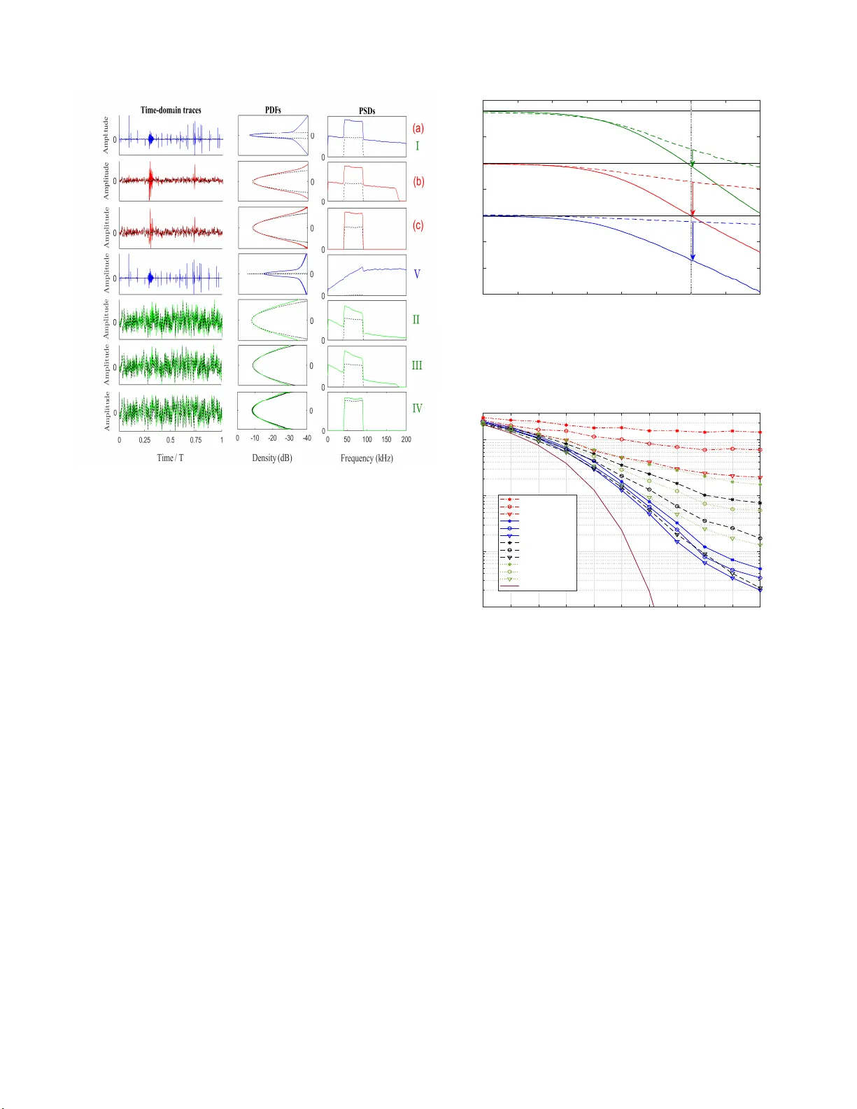
Accepted paper 2018 IEEE International Conference on Communica tio ns (ICC) Practic al Implementat ion of Adapti v e Analog Nonlinear Filtering For Impulsi ve Noise Miti gation Reza Ba razideh † , Alexei V . Nikitin † , ∗ , Ba lasubramaniam Natarajan † † Department o f Electrical and Computer Engineering, Kansas S tate University , Manhattan, KS , USA. ∗ Nonlinear Corp., W amego , KS 66547, USA. Email: { rezabarazideh,bala } @k su.edu, avn@nonlinearco rp.com Abstract —It is well known that the perf ormance of OFDM- based Powerline Communication (PLC ) systems is impacted by impulsive noise. In this work, we propose a practical blind adaptive analog nonli near filter to efficient l y detect and mitigate impulsive noise. S p ecially , we design an Adaptive Canonical Differential Limiter (A CDL) which is constructed from a Clip ped Mean T racking Filter (CMTF) and Quartile T racking Filters (QTFs). The QTFs help to determine a r eal-time range that excludes outliers. This range is fed into the CMTF which is responsible f or mitigating impul sive noise. The CM TF is a nonlinear analog filter and its nonlin earity is controlled b y the af orementioned range. Proper selection of this range ensu res the impro vement of the d esired signal quality in impulsive en vironment. It is important to note that the p roposed A CDL behav es like a li near fi lter in case of no impulsive noise. In th is context, th e traditional matched filter construction is modifi ed to ensure distortionl ess processing of th e desired signal. The perfo rmance imp ro vem ent of th e proposed A CDL is due to the fact that un like other nonlin ear methods, the A CDL is implemented in the analog domain wh ere th e outliers are still broadband and distinguishable. Simulation r esults in PRIME (OFDM-based narrowband PLC system) demonstrate the su- perior BER performance of A CDL relative to other nonli near approaches such as blanking a nd clippin g in imp ulsive noise en vironments. Index T erms —Impulsive n oise, analog n onlinear filter , adap- tive canonical differential limiter (A CDL) , cli p ped mean track- ing filter (CMTF); quantile tracking filter (QTF), orthogonal frequency-division multiplexing (OFDM ) , powerline communi- cation (PLC). I . I N T RO D U C T I O N W ith the pervasiv e reach of powerline infrastructur e, low deployment costs, and its wide frequen cy ban d, powerline commun ication ( PLC) has become a strong c a ndidate for a variety of smar t g rid app lications [1]. High speed co mmu- nication over p owerlines h as recen tly attracted con siderable interest and offer a very in teresting alternativ e to wireless commun ication s ystems. Th e ability to sup p ort high data rates in PLC req uires multicar r ier proto cols such as ortho gonal frequen cy division multiplexing (OFDM) [2]. Th e two major issues in OFDM-based PLC are: (i) imped ance m ismatch that is d u e to th e fact that the powerline infrastru cture is origin ally designed for p ower delivery an d not for c o mmunica tio ns [1], and (ii) noise that typically consists of two parts: the therm al noise, which is assumed to be add iti ve Gaussian noise, a n d impulsive no ise that may be synchron o us or asynchro nous relativ e to the main fre quency [3], [4]. Since OFDM emp loys a larger symb o l dur ation ( i. e., nar rowband subcarrier s), the energy of i mpulsive noise is natu rally spread o ver all s ubcarri- ers. While this provides some level of robustness to impulsive noise, system per forman ce can still d egrade if impulse no ise power exceed s a certain threshold [5]. A plethor a of techniqu es to m itig ate the effect of impulsive noise have b een propo sed over the past few decades. For example, chan nel coding techniques suc h as turb o codes (TC) [6] and low density par ity check codes (LDPC) [7] have been used to im prove bit error rate (BER) in imp u lsi ve noise en vironm e n ts. It has been shown that these app roaches are effecti ve only in sing le carrier sch emes and there is small gain in OFDM systems which are widely used almost in all PLC applicatio ns [ 4]. The r e d uction of signal-to- n oise ratio (SNR) in hig hly impulsive noise environments such as PLC can be too se vere to b e handled by forward error co rrection (FEC), frequen cy-domain b lock interleaving (FDI) [8] or time-dom a in block interleaving (TDI ) [9]. Many appr oaches assume a statistical m o del such as α -stable [10] and Middleton class A, B an d C [ 11] for the impu lsi ve no ise an d use parametric meth ods in the receiver to m itigate impu lsi ve noise. Such p arametric me th ods requ ire the overhead of tr a ining and parameter estimation. In addition, difficulty in parameter esti- mation an d m odel mismatc h degrade the system perform a nce in non stationary no ise. The non -Gaussian nature of impulsive noise h as also motivated th e use of various memo ryless nonlinear a pproach es such as clipping [1 2], blankin g [13], joint blank ing-clippin g [ 14], linear co m bination of blanking and clippin g [ 15], and deep clipping [16]. As shown in [2], these m ethods have go o d per f ormance only for asynchro n ous impulsive noise in high sign al-to-impu lsi ve noise ra tios (SIR) and their per f ormanc e degrades dram atically in severe impu l- si ve environment. T o address the challen ge of severe impulsiv e noise con ditions, a two-stage nu lling algorithm ba sed on iterativ e chan nel estimation is propo sed in [17] wh ic h is computatio nally intensiv e. The curren t state-of- a rt appr oach to mitigate the effects o f impulsive n oise is to convert the analo g signa l to d igital and then using d igital nonlinea r meth o ds. T his classical ap p roach has two ma in prob lems. First, the signal b andwidth dec r eases in the p r ocess of an alog-to- d igital conversion and an initially impulsive broad band n oise will appear less impulsive mak in g it challenging to remove outlier s via digital filters [1 8]- [19]. 1 Although , this p roblem ca n be overcome b y increasing th e sampling rate ( and th us th e ac quisition b andwidth ) , it exac- erbates th e memo ry , complexity and compu ta tio nal load on digital signal pro cessor ( D SP). Second, digital no nlinear filters are n ot ide ally suited to real- time pr ocessing relative to a nalog filters due to adde d com putational burden. Ther efore, in our prior work we pro posed a blind adaptive analog filter, refer red to as Adaptive Nonlinear Differential Limiter (ANDL) to mitigate imp u lsi ve noise in ana log domain before the analog - to-digital converter ( ADC) [20], [2 1]. In [20], we studied the basics o f the ANDL ap p roach and the gener al behavior o f SNR in a conc e p tual system withou t realistic OFDM trans- mitter and receiver modu les. In [21], we extended th e analysis by explicitly q u alifying the BER perfo rmance of th e ANDL in a pra ctical OFDM-ba sed PLC system. Although , in [21] a simple m e th od is p roposed to deter mine an effective value for the reso lution param e te r that m a x imizes the signal q uality while mitigating the impu lsi ve noise, findin g the re solution parameter in real-time and practical imp lementation of th e filter a r e still a open p roblem th a t we add ress in th is pap er . In th is paper, f or the first time, a practical blin d adaptive analog n o nlinear filter, refer red to as Ada p tiv e Canon ic a l Differential Limiter ( A CDL) is propo sed to mitigate the effect of imp ulsiv e n o ise in PLC system. In practice, the A CDL consists of two m odules: (i) the range modu le that uses Quartile Tracking Filters (QT Fs) to establish the rang e that excludes impulsi ve no ise, and (ii) Clipped Me an T r acking Filter (CMTF) tha t con sists of a no nlinear filter th at mitigates outliers with out k nowledge of th e n oise distribution. The effects of this filter on the desired signal are totally different relativ e to that on th e impulsive noise becau se o f non linearity of this filter . There fore, SNR in the de sired bandwid th will increase by reducing the spectral density o f n o n-Gaussian noise without significan tly affecting th e d esired signal. W e validate the per forman ce of the AC DL by measur in g the SNR and the BER o f a practical PLC system. In addition , we highligh t the prefere n ce of our approach rather than other conv entional ap proache s suc h as blankin g , clipping and lin e ar filtering. The rema inder of this pa per is o rganized as follows. Sectio n II describ es the system and noise m odels. Section I I I details the prop osed analog non lin ear filter mod ules an d their prac- tical implem entation. Section IV pr esents simulation resu lts and fin ally con clusions are drawn in Section V . I I . S Y S T E M M O D E L The OFDM-based PLC system conside r ed in this work is shown in Fig. 1. In this system, in formation bits are first modulated by phase shift keying (PSK) or q uadratur e am p li- tude mo dulation (QAM) schemes. Th e modu lated data s k are passed th rough an inverse discrete Fourier transform (IDFT) to generate O FDM symb ols over o rthogo nal subcar riers and th en shaped by a root raised cosine wav eform with roll- off factor 0 . 25 and transmitted through th e channel. The transmitted analog sign a l envelope in time domain can b e expressed as s ( t ) = 1 √ N N − 1 X k =0 s k e j 2 πkt T p ( t ) , 0 < t < T , (1) where N is the number o f subcarrie r s; T is the O FDM symbol duration ; an d p ( t ) deno tes the pulse shape. In genera l, f or different applicatio ns, we can construct an OFDM sy mbol with M non -data subcarrier s and N − M data su bcariers. The non-d ata subcar riers are either pilots for chan nel estimation and sy nchron ization, or n ull for spectral shaping and inter- carrier interf erence reductio n. Un der p erfect synch ronization , the rece ived signal in an add itiv e noise chan nel is given b y r ( t ) = s ( t ) + w ( t ) + i ( t ) . (2) Here, s ( t ) denotes th e desired signal with variance σ 2 s ; w ( t ) is complex Gaussian no ise with mean ze r o and variance σ 2 w ; and i ( t ) r epresents the impulsive no ise which is not Gau ssian and it is assum ed that s ( t ) , w ( t ) , and i ( t ) are m utually indepen d ent. In gener a l, the mo d el in (2) can b e exp a nded to in clude chann el atten uation (fading ) effect. However , sinc e the goal of the work is to demonstrate a n ovel ap p roach to mitigation o f impulsive noise, we restrict ourselves to additive noise chann el m odel in (2). It is impo rtant to note that the propo sed A CDL appr oach is ap plicable to altern ate ch annel model as well. As shown in Fig. 1, the conventional structur e of the r eceiv er is m odified in ord er to deal with impulsive noise i ( t ) and the a dditional proposed filter is implemen ted before the ADC as a front end filter . No n-Gaussian noise i ( t ) is the main challeng e in th e PLC and it has been shown b y field measurements that cyclostation ary impulsive n oise a n d asynchro nous im pulsiv e noise are dominant in narrowband PLC (NB-PLC) an d br oadban d PLC (BB-PLC), respectively [22]. Since both types of impulsive n oises are presented in the NB-PLC [ 22], [20], we conside r b o th of them simu ltane- ously . Based o n field measur ements [3], the dom in ant part of cyclostationar y impulsi ve noise is a strong and narrow exponentially d e caying no ise burst tha t occu rs perio dically with half th e alternate cu rrent (A C) cycle. As discussed in our previous work [21], th is no ise co rrespond s to i cs ( t ) = A cs ν ( t ) ∞ X k =1 exp − t + k 2 f AC τ cs ! θ t − k 2 f AC , (3) where A cs is a constant; τ cs is characteristic decay time f o r the cyclostationary noise; ν ( t ) is co mplex white Gaussian noise proce ss with zero mean and variance one; and θ ( t ) is the Heaviside u nit step functio n. Th e sp e ctral density of th is noise is shaped based on measu r ed spectr um of impulsivity in practice (p ower spectra l density (PSD) decaying at an approx imate rate of 3 0 dB per 1 MHz) [ 3]. On the oth er hand, asynchron ous imp ulsiv e consists of short duration an d high power impulses with rando m ar riv al. Accord ing to [21], this n oise can be modeled as i as ( t ) = ν ( t ) ∞ X k =1 A k θ ( t − t k ) e − t + t k τ as , (4) Constellation Mapper (PSK or QAM) 0 1 2 ... d d d 0 1 2 ˆ ˆ ˆ ... d d d Constellation Demapper & Detection P/S S/P IFFT FFT P/S S/P D/A Pulse shap ing (Root Raise d Cos ine) Modifie d Matched Filter A/D Thermal Noise + Impulsive Noise ACDL a Information Bits Fig. 1: System model block diagram. A /D M odifi e d M atched Fi l t er Broad band Lo wpass Clipped M ean Tracki n g Fi lter A nt i -alia sing T uke y ’ s R ang e Quartile T r acking Filter + A A - A A - + + g + + · V 1 1 3 ( , ) h Q Q D 3 Q - 1 Q - 1 2 A 1 2 A - • ( ) t ( ) x t G a + a - 1 x << xt 1 d t t × × × ò ( ) a a + - × × × ( ) a a + - × × × 0 1 d t T - × × × ò 0 1 d t T - × × × ò [ ] [ ] h k h k t + ] h k [ [ ( ) 3 3 1 1 Q Q Q g b + - é ù ë û ( ) 1 3 1 1 Q Q Q g b - - é ù ë û · · · · I II II I IV K ( ) r t - + Fig. 2: Practi cal implementat ion of A CDL. where A k is the am p litude of k th pulse; t k is a arrival time of a Po isson pro cess with p arameter λ ; and τ as is characteristic decay time f or the asynchrono us noise and has a duration about few microseco nds. In the next section, we discuss the A CDL desig n and im plementation in detail. I I I . P R A C T I C A L I M P L E M E N TA T I O N O F AC D L The principa l bloc k d iagram of the A CDL is shown in Fig. 2. W ithout loss of gen erality , it is assume d that th e output ranges o f th e active compo nents (active filters, integrators, and compara to rs), as well as the inp ut rang e of the ADC, are limited to a c e rtain fin ite range, e.g . , to the p ower supply ran ge ± V c . The time p arameter τ is such th at 1 / 2 π τ is eq ual to the corner frequen cy of the an ti-aliasing filter (e.g ., appr oximately twice th e b andwidth of the signal of the inter est B x ), and the time co nstant T 0 is two-to-th r ee ord ers of the magnitude larger than B − 1 x . Th e purpose of th e front-e n d lowpass filter is to limit the input noise power an d at th e sam e time its bandwidth should r emain sufficiently wid e ( i.e., ξ ≫ 1 ), so that the impulsive noise is not excessi vely spr ead out in time. In gener al, we can assume that the gain K is constant and is largely depend ed on the value of the parameter ξ (e.g., K ∼ √ ξ ), a n d the g ains G and g ar e adju sted in ord er to fully utilise the av ailable outpu t ra n ges of the active co mponen ts, and the inpu t ran g e of the ADC. For in stance, G and g may be chosen to ensure that the a verage ab solute value of the o u tput signal (i.e., o bserved at p oint IV) is app roximately V c / 10 , and the difference Q 3 − Q 1 is 2 V c / 5 . A. Clipped Mean T rac k ing F ilter (CMTF) The r ole of th e CMTF is to mitigate outliers from th e input signal and at the sam e time it should be designed to be have like a linear filter in the absence of ou tliers. As shown in the block diagram of th e CMTF in Fig. 2, the input x ( t ) an d the output χ ( t ) signals can be related by the following first ord er nonlinear differential equ ation d d t χ ( t ) = 1 τ C α + α − ( x ( t ) − χ ( t )) , (5) where th e clippin g functio n C α + α − ( x ) is define d as C α + α − ( x ) = α + f or x > α + α − f or x < α − x otherw ise , (6) where α + and α − are the u pper an d lo wer clipping values, respectively . Note that for the clipp in g values such that α − ≤ x ( t ) − χ ( t ) ≤ α + for all t, equation (5) describes a first o rder linear lowpass filter with co rner freq uency 1 / 2 π τ , and the filter shown in Fig. 2 op e rates in a linear regime as shown + Modified Matched Fil t e r Broadband Lowpass 1 st order lowpas s G Anti-aliasing Matched Fil t er Anti-alia sing [ ] [ ] h k h k t + ] h k [ [ [ ] h k @ ( ) x t ( ) x t • • • 1 x << 1 x << G 1 d ... t t ò • ( ) t (a) (b) (c) xt xt II I A /D A /D Broadband Lowpass K K - + Fig. 3: Equi valent block diagram of Fig. 2 operating in linear regi me. in Fig . 3. Howe ver, wh en the values of the difference signal x ( t ) − χ ( t ) are outside of the interval [ α − , α + ] , th e rate of change of χ ( t ) is lim ited to either α − /τ or α + /τ and no longer depen ds on the m agnitude of x ( t ) − χ ( t ) . T hus, if the values of the difference signa l that lie o utside of th e interval [ α − , α + ] are outliers, the o utput χ ( t ) will be in sensiti ve to further incr ease in th e amp litude of such o utliers. In this work, an effectiv e value of the in terval [ α − , α + ] is obtained as th e T u ke y’ s range [ 23], a linear combinatio n o f first ( Q 1 ) an d th e third ( Q 3 ) quartiles o f the linear-regime difference signal [ α − , α + ] = [ Q 1 − β ( Q 3 − Q 1 ) , Q 3 + β ( Q 3 − Q 1 )] , (7) where β is a constant co efficient (e.g., β = 3 ) . A s illustrated in panel I of Fig. 3, in th e lin ear regime the CMTF o perates as a first o rder linear lowpass filter with time con stant τ . Then the qu artiles Q 1 ( t ) and Q 3 ( t ) are obtain ed as output of the QTFs d escribed in the next subsection . B. Quartile T rac king F ilters (QTFs) Let y ( t ) be a quasi-station ary ban dpass ( zero-mea n) signal with a finite interqu artile range (IQR), char acterised by an av erage cro ssing rate h f 0 i of the threshold equ al to the third quar tile o f y ( t ) . (See [24] for discussion o f quantiles of continu ous signals, an d [25] for discussion of threshold crossing rates.) Let us furthe r consider the signal Q 3 ( t ) related to y ( t ) by th e f o llowing differential equa tio n d d t Q 3 = A T 0 sgn( y − Q 3 ) + 1 2 , (8) where A is a co nstant (with the same units as y a nd Q 3 ), and T 0 is a c o nstant with the u n its of time. A c c ording to equation (8), Q 3 ( t ) is a p iecewise-linear sig n al consisting of the altern ating segments with positiv e (3 A/ (2 T 0 )) and negativ e ( − A/ (2 T 0 )) slopes. Note th at Q 3 ( t ) ≈ co nst for a sufficiently small A/T 0 (e.g., mu c h sm aller than the prod uct of the I QR an d the average cr ossing rate h f 0 i of y ( t ) and its third qu artile), an d a steady-state solution of equation (8) can be written imp licitly as θ ( Q 3 − y ) ≈ 3 4 , (9) 0 1 2 3 4 5 6 7 8 Amplitude Fig. 4: Illustra tion of QTFs’ con ver gence to steady state for diffe rent initial conditi ons. Eb/N0 = 0 dB, SIR = 0 dB. where the over-line denotes averaging over some time interval ∆ t ≫ h f 0 i − 1 . Thus, Q 3 approx imate the th ird qu artile of y ( t ) in the time interval ∆ t . Similarly , f or d d t Q 1 = A T 0 sgn( y − Q 1 ) − 1 2 , (10) a stead y-state solu tio n can be wr itten as θ ( Q 1 − y ) ≈ 1 4 , (11) and thu s Q 1 would appr o ximate the first qu a rtile of y ( t ) in the time interval ∆ t . Fig . 4 provid es an illustration o f the QTFs’ conv ergence to the steady state for different initial condition s. In Fig. 4 signal y ( t ) plotted b y green line, first (red line) and third ( blue line) qu artiles, in co m parison with the exact quartiles of y ( t ) computed in th e f ull shown tim e interval (black lines). C. Matched filter Modificatio n In the a b sence of the CMTF in the sign a l chain , the match ed filter (MF) following the ADC would have the impu lse response h [ k ] that can be viewed as a digitally sampled continuo us-time imp u lse response h ( t ) as shown in p a nel II of Fig. 3. Since o ur prop osed filter should not have any n egati ve impact when there is no im pulsiv e no ise, it is essential to modify the MF to com p ensate f or th e CMTF in a line ar ch ain. W e pr oposed a mod ification in the digital domain becau se it 1 6 11 16 21 26 31 0.2 0.4 0.6 0.8 1 1.2 1.4 1.6 1.8 2 0 0.5 1 1.5 Fig. 5: Impulse and frequenc y response of matched filter and modified matched filter . is simpler and doe s n ot need any extra co mponen ts. In case of no impulsive n oise CMTF acts like a first order lin e ar lowpass filter with time co nstant τ . Theref o re, the r e la tio n b etween the input x ( t ) an d the outpu t χ ( t ) can be expre ssed as x ( t ) = χ ( t ) + τ ˙ χ ( t ) . (12) In the line ar regime we want to hav e same result either with or without CMTF (Panels I and II in Fig. 3) . Thus, the outpu t of mod ified matched filter with the input χ ( t ) sh o uld be eq ual to the ou tput of MF with the inp ut x ( t ) . Theref o re, we h av e χ ( t ) ∗ h mo d ( t ) = x ( t ) ∗ h ( t ) = ( χ ( t ) + τ ˙ χ ( t )) ∗ h ( t ) , (13) where the asterisk den otes conv olution and th e im pulse re - sponse h mo d [ k ] of the mo dified matched filter in the digital domain can be expressed as h mo d [ k ] = h [ k ] + τ ˙ h [ k ] . (14) The impulse and freq uency respon ses o f the match ed filter (a r oot-raised- cosine filter with roll-off factor 1 / 4 , ban dwidth 5 B x / 4 , and the samplin g r a te 8 B x ) and the mo dified matched filter (with τ = 1 / (4 π B x ) ) are shown in Fig. 5. In the presence of CMTF the com pensation of the modified match ed filter on the BER per f ormance of a OFDM sy stem with B x = 50 k Hz and BPSK modu lation is shown in Fig . 6. As it can be seen the effect of CMTF in linear chain comp letely alleviated by the mod ified matc h ed filter which mean s th at our pro posed filter do es not harm the desired signal in case of n o impu lsi ve noise. I V . S I M U L AT I O N R E S U LT S As a specific exam ple, we simu late an OFDM- based PLC in acco r dance with the PRIME standard [26]. The sampling frequen cy is chosen as f s = 2 50 kHz and the FFT size is N = 5 1 2 , i.e., the subcarrier spacing f = 488 Hz. As carriers 8 6-182 are used for d ata tra nsmission, the PRIME signal is located in the freque ncy range 42-89 kHz [26]. -4 -2 0 2 4 6 8 Eb/N0 (dB) 10 -4 10 -3 10 -2 10 -1 BER Modified Matched Filter Matched Filter Theoretical AWGN Fig. 6: P erformance comparison be tween matched fil ter and modified matched filter in the presence of CMTF for BPSK m odulat ion. The system is studied in a noise en vironmen t an d it con- sists of three co mponen ts: (i) a thermal noise (ii) p eriodic cyclostationary exponentially decay ing compo nent with the repetition frequ ency at twice th e A C line frequen cy ( 2 × 60 Hz) and τ cs = 200 µs (on e tenth of OFDM symb ol), an d (iii) asynch ronou s random impu lsi ve n o ise with nor mally distributed amplitudes captu red by a Poisson arriv al process with parameter λ and τ as = 2 µs . Based o n IEE E P1901.2 standard [3] the PSD of noise com ponents ( i) and (ii) d ecay a t a rate of 30 dB per 1 MHz. Since the cyclostationary noise is dominan t in the NB-PLC, we set the power of th is comp o nent three times higher th an the asyn chrono us imp u lsi ve noise. T o emulate the analog signals in the simulation, the digitization rate is chosen to be significantly high e r (b y about two orde r s of magn itude) tha n the ADC sampling rate. In the fo llowing, SNR a n d BER of an OFDM system with BPSK m odulation are used as two metr ic s to ev aluate the perf ormance o f the propo sed analog no nlinear filter in comparison with other conv entional app roaches such as linea r filterin g, blankin g and clipping. Fig. 7 shows an in formative illustration of the chan g es in the signa l’ s time and frequ ency d omain pro perties, and in its amplitude distribution, while it prop agates thro ugh the sign a l processing chains. Sp ecifically the pro perties with a linear chain (p oints (a ), (b ), and (c) in panel II o f Fig. 3) and the ACDL (poin ts I th rough V in Fig. 2) are h ig hlighted. In Fig. 7, the b lac k dashed lines co rrespon d to the desired sign al (without noise), an d the colore d solid line s correspo nd to the signal+noise m ixtures based on the PRIME standard. The leftmost panels show th e time domain traces, the r ightmost panels show the PSDs, and the middle panels show the amplitude densities (PDFs). The value of parame ter β f or T ukey’ s range is set to β = 3 . As it can be seen in th e panels of ro w V , the difference signal largely reflects the temporal b ehavior and the amplitude o f the n oise. Thu s, its output can be u sed to ob tain th e range for identifyin g the n o ise outliers (i. e., the clipp ing value V c /g ). From the panels of Fig. 7: Illustra tion of changes in the s ignal time- and frequency domain properti es, and in its amplitud e distrib ution. Eb/N0 = 10 dB, SIR = 1 dB. row II, it is clear tha t CMT F disprop ortionately affects signals with different temporal and/or amplitude structures an d th en reduces th e spectra l density o f the impulsive no ise in th e signa l passband w ith out significan tly affecting the signal o f interest. The anti-aliasing ( r ow III) a n d the ba seb and (r ow IV) filters further r educe the rema ining noise to within the baseba n d, while the mo dified m atched filter a lso comp ensates for th e insertion of the CMTF in the sign al chain. By comparin g the panels of r ow ( c) and row IV (specially PSDs panels), one can see the ach iev ed impr ovement due to A CDL in the quality of the baseband signal is significant. In the following, we sh ow the a f orementio ned impr ovement in ter ms of SNR a nd BER. Fig. 8 compares the output SNR perform a nce for the linear pr ocessing chain and AC DL for v arious signal+n o ie composition s. As o ne can see in Fig. 8, f or an effecti ve value β = 3 , bo th linear and A CDL provide effecti vely equiv alent perform ance when ther mal noise dominates the impulsive noise. Howe ver , the ACDL shows its potency when the impulsive noise is dominant and in low SNR (SNR less than zer o ) its p erform a n ce is insensitiv e to further incr e ase in the im pulsive noise. The robustness of th e ACDL in d ifferent types of impu lsi ve no ise is demonstrated by consid e ring the case wh en both asynchro nous an d cyclostationary impu lsi ve noise im pact the signal simultaneou sly . Th e BER perf o rmance of the ACDL f or different values o f SIR versus Eb /N0 is shown in Fig. 9. The perf o rmance of the ACDL is comp ared with linear filter, blan king and clippin g when the op timum thresholds for blankin g an d clipping are found based on -20 -15 -10 -5 0 5 10 15 20 Impulsive noise to thermal noise ratio in baseband (dB) -15 -10 -5 0 5 10 15 20 Output SNR (dB) ACDL (dashed Lines) LIN (Solid Lines) 7.5 dB 6.5 dB Eb/N0 = 20 dB Eb/N0 = 10 dB Eb/N0 = 0 dB 3.3 dB Fig. 8: Comparison of output SNR for the linear processing chain (solid lines) and AC DL (dashed lines). 1 /λ = 2 e − 5 s . -4 -2 0 2 4 6 8 10 12 14 16 Eb/N0 (dB) 10 -4 10 -3 10 -2 10 -1 BER LIN, SIR = -3 dB LIN, SIR = 0 dB LIN, SIR = 3 dB ACDL, SIR = -3 dB ACDL, SIR = 0 dB ACDL, SIR = 3 dB BLN, SIR = -3 dB BLN, SIR = 0 dB BLN, SIR = 3 dB CLP, SIR = -3 dB CLP, SIR = 0 dB CLP, SIR = 3 dB Theoretical AWGN Fig. 9: BER versus Eb/N0 with fixed SIR. 1 /λ = 2 e − 5 s . an exha u sti ve numerical search. Fig. 9 shows that ACDL outperf orm oth er app roaches, especially at h igh SNR. It is imp ortant to m ention that the rang e [ α − , α + ] in Fig. 9 are determined by QTFs module an d β = 3 whic h is an effecti ve value for ran ge α but n ot th e op tim um on e . It is clear that a fixed value o f β can not g u arantee the optimum value of α for all kinds of noise, but an effecti ve value of β f or a specific app lication can b e easily found by training the A CDL in a short dura tion o f time . The effect of β on the per forman c e of the A CDL is illustrated in Fig. 10. As it ca n be seen the value of β is cr itica l esp e c ially at high SNR but selectin g a value n ear the op tim um one ( e.g., β = 2 . 5 , 3 . 5 in Fig . 10) can ensur e a reasonable perfo rmance. Using inef ficient β , i.e., with high deviation from the effecti ve value, may cause considerab le perf ormance d egradation at higher SNR. Such behavior is due to inappro priate elimination of the impulsive noise o r cr opping the desired signal in large or small β values, respectively . -4 -2 0 2 4 6 8 10 12 14 16 Eb/N0 (dB) 10 -4 10 -3 10 -2 10 -1 BER = 0.5 = 1 = 1.5 = 2 = 2.5 =3 = 3.5 = 4 Theoretical AWGN Fig. 10: E f fect of β on ACDL performance. SIR = 0 dB, 1 /λ = 2 e − 5 s . V . C O N C L U S I O N In this work , a practical implementation of adap ti ve an alog nonlinear filter , ref erred to as Adaptive Can onical Differential Limiter (ACDL) is prop osed to mitigate impulsive noise. Th e A CDL consists of two m odules: Clipped Mean T racking Filter (CMTF) and Qu artile Tracking Filters (QTFs), which take care of ou tliers m itigation and finding a rea l- time range for parameter α , respectively . In add ition, a mod ified match filter is intr oduced to alleviate th e effect of CMTF . W e d emonstrate the performa nce of the A CDL consider ing an OFDM-b a sed PLC sy stem with b oth asyn chrono us an d cyclostationary impulsive noises. The results show that the ACDL can pro- vide improvement in the overall signal q u ality r anging from distortionless b e havior fo r low impu lsive n oise cond itions to significant imp rovement in SNR or BER pe r forman ce in the presence of a stro ng im pulsive compone n t. Moreover , the A CDL ou tperfor ms other appr oaches such as blank ing and clipping in r educing the BER in impulsive no ise environments. It is important to note that our filter can be dep loye d either as a stand-alo ne low-cost real-time solu tion for impu lsi ve no ise mitigation, or combin ed with oth e r interf erence reduction technique s. R E F E R E N C E S [1] S. Galli, A. Scaglione, and Z. W ang, “For the grid and through the grid: The role of power line communicat ions in the sm art grid, ” Pr oc. IEEE , vol. 99, no. 6, pp. 998–1027, Jun. 2011. [2] S. V . Zhidko v , “ Analysis and comparison of se ve ral s imple impulsiv e noise mitigat ion schemes for OFDM recei vers, ” IEEE T rans. Commun. , vol. 56, no. 1, pp. 5–9, Jan. 2008. [3] IEEE Standar d for low frequ ency narr owband power line communica - tions , Std., 2012. [4] G. Ndo, P . Siohan, and M. H. Hamon, “ Adapti ve noise m itiga tion in impulsi ve en vironment: Applicati on to power -line communications, ” IEEE T rans. P ower Del. , vol. 25, no. 2, pp. 647–656, Apr . 2010. [5] M. Ghosh, “ A nalysis of the effe ct of impulse noise on multica rrier and single carrier QAM systems, ” IEEE T rans. Commun. , vol. 44, no. 2, pp. 145–147, Feb . 1996. [6] D. Umehara, H . Y amaguchi, and Y . Morihiro, “Tu rbo decoding in impulsi ve noise envi ronment, ” in Global T elecommu n. Conf . , vol. 1, Nov . 2004, pp. 194–198. [7] H. Nakagaw a, D. Umehara, S. Denno, and Y . Morihiro, “ A decodin g for lo w density parity check codes ov er impulsi ve noise channels, ” in International Symposi um on P ower Line Communications and Its Applicat ions, 2005. , April 2005, pp. 85–89. [8] M. Nassar, J. L in, Y . Mortazavi , A. Dabak, I. H. Kim, and B. L. Eva ns, “Local util ity po wer line communicati ons in the 3–500 kHz band: Channel impairments, noise, and standards, ” IE E E Signa l Pr ocess. Mag . , vol . 29, no. 5, pp. 116–127, Sep. 2012. [9] A. Al-Dweik, A. Hazmi, B. Sharif, and C. T simenidis, “Effici ent inter- lea ving technique for OFDM system ove r impulsiv e noise channels, ” in Pr oc. IEEE Int. Symp. on P ersonal, Indoor and Mobile Radio Commun. , Sep. 2010, pp. 167–171. [10] G. Samorodnitsk y and M. S. T aqqu, Stable Non-Gaussian Random Pr ocesses: Stoch astic Models with Infinite V ariance . New Y ork: Chapman and Hall, 1994. [11] D. Middle ton, “Non-Gaussian noise models in signal processing for telec ommunicati ons: New methods and results for class A and class B noise m odels, ” IEEE T rans. Inf. Theory , vol. 45, no. 4, pp. 1129–1149, 1999. [12] D. -F . Tseng et al. , “Rob ust clippin g for OFDM transmissions over memoryless impulsi ve noise channels, ” IEEE Commun. Lett. , vol. 16, no. 7, pp. 1110–1113, J ul. 2012. [13] C.-H. Y ih, “Iterati ve interfer ence cancella tion for OFDM signals with blankin g nonlinea rity in impulsi ve noise channels, ” IE E E Signal P r o- cess. Lett. , vol . 19, no. 3, pp. 147–150, Mar . 2012. [14] M. Korki, N. Hosseinzad eh, H. L. V u, T . Moazzeni, and C. H. Foh, “Impulsi ve noise reduction of a narrowba nd powe r line communication using optimal nonlineari ty technique , ” in Pr oc. Aust. T elecomm. Netw . and App. Conf. , N ov . 2011, pp. 1–4. [15] F . H. Juwono, Q. Guo, Y . Chen, L. Xu, D. D. Huang, and K. P . W ong, “Linear combining of nonlinear preproce ssors for ofdm-based power - line communications, ” IEEE T ransactions on Smart Grid , vol. 7, no. 1, pp. 253–260, Jan 2016. [16] F . H. Juwono, Q. Guo, D. Huang, and K. P . W ong, “Deep clip ping for impulsi ve noise m itiga tion in ofdm-based power -line communication s, ” IEEE T ransactions on P ower Delivery , vol. 29, no. 3, pp. 1335–1343, June 2014. [17] Y . R. Chien , “Iterati ve channel estimation and impulsi ve noise mitiga- tion algorithm for ofdm-based recei vers with applicat ion to power -line communicat ions, ” IEEE T rans. P ower Del. , vol. 30, no. 6, pp. 2435– 2442, Dec. 2015. [18] A. V . Nikitin, “On the intercha nnel interference in digita l communica- tion s ystems, its impulsiv e nature, and its m itiga tion, ” E URASIP J. Adv . Signal Proce ss. , no. 1, p. 137, Dec. 2011. [19] A. V . Nikitin, R. L. Davidchac k, and J. E. Smith, “Out-of-band and adjac ent-cha nnel int erferenc e reduction by analog nonlinear filters, ” EURASIP Journal on Adv . in Sig. Pr ocess. , no. 1, p. 12, Dec. 2015. [20] A. V . Nikitin, D. Scutti, B. Natarajan, and R. L. Davidchac k, “Blind adapti ve anal og nonlin ear filters for noise mitigat ion in po werline communicat ion systems, ” in Pr oc. IEEE Int. Symp. on P ower Line Commun. and its Appl. , Mar . 2015, pp. 1–6. [21] R. Barazideh , B. Nataraj an, A. V . Nikitin, and R. L. Davidc hack, “Per- formance of analog nonlinear filtering for impulsi ve noise mitigation in OFDM-based PL C systems, ” in IEEE Latin-American Confere nce on Communicat ions (LATINCOM) , Nov 2017, pp. 1–6. [22] J . Lin, M. Nassar , and B. L. Evan s, “Impulsiv e noise m itigation in po werline communicati ons using sparse Bayesi an lea rning, ” IEEE J. Sel. Areas Commun. , vol. 31, no. 7, pp. 1172–1183, Jul. 2013. [23] J . W . T uke y , Explorat ory Data Analysis . Addison-W esley , 1977. [24] A. V . Nikitin and R. L. Davidchac k, “Signal analysis through analog represent ation, ” in P r oc. Royal Society of London A: Mathe matical , Physical and Engineering Sciences , vol. 459, no. 2033, May 2003, pp. 1171–1192. [25] S. O. Rice, “Mathemat ical analysis of random noise, ” The Bell System T echnic al Journa l , vol. 23, no. 3, pp. 282–332, July 1944. [26] M. Hoch, “Compari son of PL C G3 and PRIME, ” in Pr oc. IEEE Int. Symp. on P ower Line Commun. and its Appl. , Apr . 2011, pp. 165–169.
Original Paper
Loading high-quality paper...
Comments & Academic Discussion
Loading comments...
Leave a Comment