Cognitive UAV Communication via Joint Trajectory and Power Control
This paper investigates a new spectrum sharing scenario between unmanned aerial vehicle (UAV) and terrestrial wireless communication systems. We consider that a cognitive/secondary UAV transmitter communicates with a ground secondary receiver (SR), i…
Authors: Yuwei Huang, Jie Xu, Ling Qiu
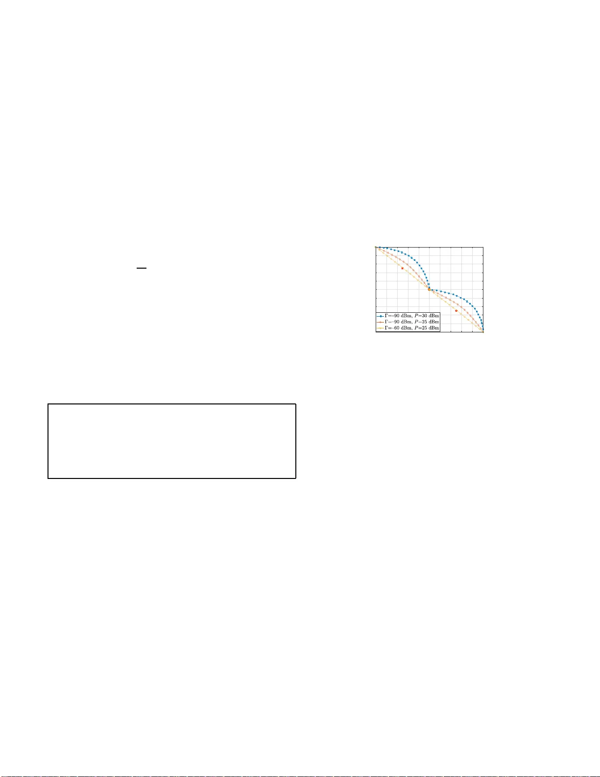
Cogniti v e U A V Communication via Joint T rajectory and Po wer Control (In vited P ape r) Y uwei Huang 1 , Jie Xu 2 , Ling Qiu 1 , and Ru i Zha ng 3 1 School o f Informati on Scien ce an d T echno log y , Uni versity of Science and T echn ology of China 2 School of Information Enginee ring, Guan g dong University of T ec h nology 3 Department of Elec trical a nd Computer Eng ine ering, Nationa l Uni versity of Sing apore E-mail: hyw1023@mail.ustc.e du.cn, ji exu@gdut.edu .cn, lqiu@ustc.edu.c n, elezha ng@nus.e du.sg Abstract —This paper in vestiga tes a new spectrum sharing scenario between unmanned aerial ve hicle (U A V) and terr estrial wireless communication systems. W e consider that a cogni- tive /secondary U A V transmitter communicates wi t h a ground secondary recei ver (SR), in the pr esence of a number of primary terrestrial communication li nks that operate over the same frequency b and. W e exploit the U A V’s controllable mobility via trajectory design, to improv e the cognitive U A V communication perfo rmance while cont rolling the co-channel interference at each of the primary receiv ers (PRs). In particular , we maximize the ave rage achievable rate from the U A V to the S R over a fi nite mission/communication period by jointly opti mizing the U A V trajectory and transmit power allocation, subject to constraints on the U A V’s maximum speed, ini tial/final locations, and a verag e transmit power , as well as a set of interference temperature (IT) constraints imp osed at each of the PRs f or protecting their communications. Ho wever , the joint t rajectory and power optimization pro blem is non-con vex and thus difficult to be solved opti mally . T o tackle this problem, we propose an efficient algorithm that en sures to obtain a locally o ptimal solution by applying the techniq u es of alternating optimization and successive con vex approximation (SCA). Numerical results show th at our proposed joint U A V trajectory and p ower control scheme significantly enhances the achieva ble rate of the cognitive U A V communication system, as compared to benchmark schemes. Index T erms —Unmanned aerial vehicle (U A V), U A V commu- nication, cognitive radio, trajectory d esign , power control. I . I N T RO D U C T I O N Unmanne d aerial vehicles (UA Vs) or drones a r e anticipated to have abundant civil applications in the fu ture, for e. g . cargo delivery , agr iculture inspectio n, surveillance, rescu e and search, an d communication relay in g [ 1 ]. As the number o f U A Vs increases explo sively , it is c r ucial to provide them with seamless wireless data connections, in order to n ot only support secu re, reliab le, and low-latency remo te comman d and control, but also enable high-capa c ity mission- r elated d ata transmission. There are gen erally two approaches to realize U A Vs’ commun ication with their ground users, namely the conv entional direct UA V -to- groun d com m unication and the newly propo sed cellular-connected U A V co mmun ic a tion [ 2 ]. In the former appro ach, UA Vs are directly con nected with groun d control stations via point-to -point wireless co mmu- nications; while in the latter case, UA Vs are integrate d into cellular networks as a new type of mo bile users. As compar e d to the conventional direct U A V -to-gro und commu nication, the cellular-connected UA V can considera bly improve the com mu- nication perfor mance in terms of reliability , throu ghpu t, secu- rity , etc., and thu s significantly inc r ease the UA Vs’ operation range. Due to th e scarcity o f wireless spe ctrum, for both ap- proach e s above, U A Vs may need to share the spectrum w ith existing wireless devices (e.g ., cellular mobiles on th e g roun d) for commu nications [ 3 ]. This resembles spec tr um sharing in cognitive radio (CR) network s, in which secondary users share the same freque n cy bands with existing primary u sers [ 4 ]. In this case, the U A V -to -grou nd communication may cause severe interferen ce to th e existing terrestrial user s, as U A Vs usually have strong line-of-sigh t (LoS) lin k s with ground nodes such as cellula r base stations ( BSs), du e to their high altitud e over the air . As a result, h ow to optimize the UA V commu nication perfor mance while effectively controlling the air-to-grou nd co- channel inter ference is a n ew and ch allenging p roblem to be solved. By leveraging the UA V’ s con tr ollable m obility , in this paper, we prop ose a new appro ach to so lve th is pro blem, which jointly optimize s th e UA V trajectory and tran smit power allocation to achieve the maximum thro ughpu t of the U A V - to-gro u nd comm unication an d yet control the interference to existing g round r eceivers b elow a tolerable lev el. Specifically , th is pap er con siders a cognitive UA V commu- nication system, where a cognitive/secondary UA V transmitter commun icates with a ground secondar y receiver (SR), in th e presence of a n umber o f p rimary terr estrial comm u nication links that opera te over the same frequ ency band. W e adopt the interfer en ce temperatur e (IT) method in CR networks [ 5 ], [ 6 ] to protect the primary com municatio n links, based on which the received interfer ence p ower a t each primary receiver (PR) cannot exceed a prescribed IT thresho ld. Und er this setup, we maximize the average achiev able rate of the co gnitive U A V commun ication over a finite UA V mission/commu nication period, b y jointly o ptimizing the U A V tr ajectory and transmit power allocatio n, subje c t to the maximum sp eed, initial/final locations and a verage tra n smit power con stra ints o f the UA V , as well as the average IT constrain ts at the PRs. Howe ver, the joint trajecto ry and power op timization pro b- lem is n on-co n vex and th us difficult to be solved op timally . T o tack le this problem, we p r opose an efficient algorith m that ensures to ob ta in a locally optima l solution by apply- ing the techniqu es of alter nating op timization and successi ve conv ex app roximatio n ( SCA). Num erical results show that our propo sed joint U A V trajectory and power control scheme significantly im p roves the achievable rate of the cognitive U A V commun ication system, as com pared to benchma r k schemes with trajectory optimization or p ower control only . Note that in th e litera tu re, there h ave b een a han d ful o f works th a t studied the U A V’ s trajectory design for im proving the UA V co mmunicatio n perform ance under different setups [ 2 ], [ 7 ] –[ 13 ]. For example, [ 7 ], [ 8 ] em ployed the U A V as a mobile relay to help enhance the commu nication throughpu t between two ground users. [ 9 ]–[ 1 3 ] employed U A Vs as aerial BSs to broadcast individual inf o rmation o r multicast commo n informa tio n to a set o f g round users. A cellu lar-connected U A V application was considered in [ 2 ], wh ich optimized the U A V trajectory to m inimize the m ission com pletion time, subject to the communicatio n connectivity constraints with groun d BSs. Furthermo re, in an other line of work, UA Vs were con sidered as mobile acc e ss po ints ( A Ps) for charging gro und In te r net-of- things (IoT ) d evices [ 14 ] and simu ltaneously collecting inf or- mation from them [ 15 ]. Dif ferent from these prior works, th is paper aims to in vestigate the new spectrum sharing scenario between U A V and terre strial wire less commu nication systems, while we exploit the join t U A V tra je c tory d esign and transmit power con trol for b oth enhancing th e U A V commu nication throug hput as well as effecti vely c ontrolling the air-to-gro u nd interferen ce to terrestrial users. I I . S Y S T E M M O D E L In th is pape r, we con sid er the scenario where a co gni- ti ve/secondary UA V transmitter sen ds info rmation to a grou nd SR, in the presence of a set of K ≥ 1 primar y users that operate over th e same frequen cy band. Let K , { 1 , . . . , K } denote the set of grou nd PRs. This ma y corr espond to the uplink tran smission fro m the UA V to its associated ground BS ( SR) in a cellular network, while there ar e K gr o und users in the ne ig hborh ood simu ltan eously tran smitting to th e ir respective gro und BSs (PRs) at the same frequency band. W e focus on the co g nitive U A V com munication over a p articular mission period, denote d by T = [0 , T ] , with duration T > 0 in second (s). W e consider a three-d imensional (3 D) Cartesian coo rdinate system, where the SR and each PR k ∈ K have fixed locations of w = ( x, y ) and w k = ( x k , y k ) , respectively . It is assumed that th e UA V p erfectly knows the locatio ns of the gr ound SR and PRs a-priori to facilitate the join t trajectory and power contr ol d esign. W e assume th at the U A V flies at a constant altitud e H > 0 in meter (m) w ith the time-varying horizon tal location ˆ q ( t ) = ( ˆ x ( t ) , ˆ y ( t )) , t ∈ T . Specifically , the UA V’ s initial an d final ( h orizon tal) loca tio ns are p re- determined as ˆ q I = ( x I , y I ) and ˆ q F = ( x F , y F ) , respectively . Let ˆ V d enote the maximu m U A V speed in m/s. The n we have q ˙ ˆ x 2 ( t ) + ˙ ˆ y 2 ( t ) ≤ ˆ V , ∀ t ∈ T , wh ere ˙ ˆ x ( t ) and ˙ ˆ y ( t ) de note the first deriv a tives of ˆ x ( t ) an d ˆ y ( t ) , respectively . For ease of exposition, we discretize the mission/co m municatio n perio d T into N time slots each with equ al d uration δ t = T / N , wh ere N is chosen to be suf ficiently large such that the U A V location can be assumed to b e approximate ly con stant within each time slot. Accordin g ly , let q [ n ] = ( x [ n ] , y [ n ]) d enote the horizontal U A V locatio n at time slot n ∈ N , { 1 , . . . , N } . As a result, we have the f ollowing constraints on the UA V trajectory . k q [ n ] − q [ n − 1] k 2 ≤ V 2 , (1) q [0] = ˆ q I , (2) q [ N ] = ˆ q F , (3) where V , ˆ V δ t denotes th e maximum U A V displacemen t during ea c h tim e slot, and k · k denotes the Euclidean norm. Furthermo re, at time slot n ∈ N , the distance b etween th e U A V and the SR and that b etween the UA V and each PR k ∈ K are r espectively gi ven by d ( q [ n ]) = p H 2 + k q [ n ] − w k 2 , (4) d k ( q [ n ]) = p H 2 + k q [ n ] − w k k 2 . (5) In practice, th e air-to-gr ound wireless channels are n ormally dominated by the LoS link [ 7 ]. There f ore, similarly as in [ 7 ] , we con sid e r the free-space path- loss mod el for th e wireless channels fro m the UA V to th e SR and PRs. As a result, at time slot n ∈ N , the cha nnel power gain from the U A V to the SR and th at to each PR k ∈ K ar e respectively expressed as h ( q [ n ]) = β 0 d − 2 ( q [ n ]) = β 0 H 2 + k q [ n ] − w k 2 , (6) g k ( q [ n ]) = β 0 d − 2 k ( q [ n ]) = β 0 H 2 + k q [ n ] − w k k 2 , (7) where β 0 denotes the ch annel power gain at the re f erence distance of d 0 = 1 m. Ac cording ly , by letting p [ n ] ≥ 0 denote the transmit power of the U A V at time slot n ∈ N , the achiev able rate from the U A V to the SR in bits/second/Hertz (bps/Hz) at time slot n is R ( p [ n ] , q [ n ]) = log 2 1 + h ( q [ n ]) p [ n ] σ 2 , = log 2 1 + η 0 p [ n ] H 2 + k q [ n ] − w k 2 , (8) where σ 2 denotes th e noise p ower at the SR recei ver , and η 0 = β 0 /σ 2 denotes the ref erence signal-to-noise ratio (SNR). Note that σ 2 also takes into accou n t th e interference from the pr imary transm itter s (PTs). Let P d enote the maximu m av erage transmit p ower at the UA V . W e thus have 1 N N X n =1 p [ n ] ≤ P. (9) Under spectru m sharing, the secondary U A V co mmunica tion system intro duces air-to-grou nd co-ch annel interferen ce to the groun d PRs. At time slot n ∈ N , the interf erence power from the U A V to each PR k ∈ K is Q k ( p [ n ] , q [ n ]) = g k ( q [ n ]) p [ n ] = β 0 p [ n ] H 2 + k q [ n ] − w k k 2 . (10) In order to protect the primary communication s, we apply the IT constraint [ 5 ], [ 6 ] at each PR k , such that the received av erage interferen ce power does not exceed the IT threshold, denoted by Γ k ≥ 0 , k ∈ K . 1 W e thus have 1 N N X n =1 β 0 p [ n ] H 2 + k q [ n ] − w k k 2 ≤ Γ k , ∀ k ∈ K . (11) Our objecti ve is to maxim ize the average achiev ab le rate of the secondary U A V commun ication system (i.e., 1 N N P n =1 R ( p [ n ] , q [ n ]) ), by jointly optimizing the U A V trajector y { q [ n ] } and the transmit p ower allocation { p [ n ] } , sub ject to the U A V maxim um spee d co nstraint in ( 1 ), the initial/final location constraints in ( 2 ) and ( 3 ), the a verage tran smit p ower constraint in ( 9 ), an d the IT con straints in ( 11 ). Th erefore , th e problem of our interest is f o rmulated as ( P1 ) : max { p [ n ] , q [ n ] } 1 N N X n =1 log 2 1 + η 0 p [ n ] H 2 + k q [ n ] − w k 2 s.t. p [ n ] ≥ 0 , ∀ n ∈ N , (12) ( 1 ), ( 2 ), ( 3 ), ( 9 ) , and ( 1 1 ) . Note that p r oblem (P1) is a no n-conve x optimization prob lem, as the objec ti ve fun ction is non- concave an d th e c o nstraints in ( 11 ) are non -conve x. Theref ore, this prob lem is generally difficult to be solved o ptimally . Remark 2.1: It is worth nothing that u n der given U A V trajectory { q [ n ] } , the transmit power allocation in (P1) is reminiscent of th at for th r ough p ut maximization in fadin g CR channels ( see, e.g., [ 16 ]). Howev er , dif ferent fro m conventional fading CR chan nels with rand om wirele ss chan nel fluctua tions, the cognitive UA V communicatio n sy stem can prop erly design the U A V trajectory for controlling the wireless ch annel power gains ov er time ( see (P1)). This thus provides a new and unique d esign degree of freed o m for com m unication perfo r- mance optimization . I I I . P RO P O S E D S O L U T I O N T O P RO B L E M ( P 1 ) In this section, we pr esent an efficient algorithm based on alternating o ptimization, to obtain a locally o ptimal solu tion to (P1), by optimizing one o f the tran smit power { p [ n ] } and the U A V tra je c tory { q [ n ] } with the oth er fixed in an alternating manner . A. T ransmit P ower Optimization Under Given T rajectory First, w e op timize the transmit power allocation { p [ n ] } under any g iven U A V trajecto ry { q [ n ] } , fo r which the problem is expressed as ( P2 ) : max { p [ n ] } 1 N N X n =1 log 2 1 + η 0 p [ n ] H 2 + k q [ n ] − w k 2 s.t. ( 9 ), ( 11 ) , an d ( 12 ) . Notice that prob lem (P2) is a conve x optim ization pro blem, as the o bjective function o f (P2) is concave with respect to { p [ n ] } , and all th e co nstraints ar e co n vex. Therefor e, problem (P2) can be solved op timally b y standa r d co nvex optimizatio n technique s, such as the interior p oint method [ 17 ]. 1 In this work, w e consid er the averag e IT constraint instead of the peak IT constrai nt, as it has been s hown in [ 6 ] that the former leads to better achie vabl e rates than the latter for both the primary and secondary links, under the same total resulte d inter ference power ove r time. B. T rajectory Optimization Un der Given T ransmit P ower Next, we optim ize th e UA V trajectory { q [ n ] } under any giv en transmit power { p [ n ] } , f or which the prob lem is f ormu- lated as ( P3 ) : max { q [ n ] } 1 N N X n =1 log 2 1 + p [ n ] η 0 k q [ n ] − w k 2 s.t. ( 1 ), ( 2 ), ( 3 ) , and ( 11 ) . Notice that p r oblem (P3) is non-convex, as the o bjective func- tion is no n-conc av e with respect to q [ n ] an d th e con straints in ( 11 ) are non-c o n vex. T o tackle this pro blem, we adopt the SCA techniq u e to obtain a loca lly optima l solution to (P3) in an iterati ve manner . The ke y idea of the SCA is that giv en a local point at each iteration , w e approx imate the no n- concave ob jectiv e functio n (or the non -conve x constra in ts) into a concave objective function (conve x constraints), in order to o btain an app roximated convex optimiza tion p r oblem. By iteratively solving a sequ ence of a pprox imated con vex problem s, we can obtain a n efficient so lu tion to the original non-co n vex optimization problem (P3). Specifically , suppo se that { q ( j ) [ n ] } corresponds to the ob- tained U A V trajectory at the ( j − 1 ) -th iteration with j ≥ 1 , where { q (0) [ n ] } cor respond s to the initial U A V trajector y . I n the following, we explain how to appro ximate the ob jectiv e function of (P3) and the co nstraints in ( 11 ), respectively . First, as for the n on-co n cave o b jectiv e function of (P3), w e have the following lemma. Lemma 3.1: For any given { q ( j ) [ n ] } , j ≥ 0 , it follows that R ( p [ n ] , q [ n ]) ≥ R lb ( p [ n ] , q [ n ]) , ( 13) where R lb ( p [ n ] , q [ n ]) , log 2 1 + η 0 p [ n ] H 2 + k q ( j ) [ n ] − w k 2 − η 0 p [ n ] log 2 e k q [ n ] − w k 2 − k q ( j ) [ n ] − w k 2 ( H 2 + k q [ n ] − w k 2 ) (( H 2 + k q [ n ] − w k 2 ) + η 0 p [ n ]) , (14) and the in equality in ( 13 ) is tight for q [ n ] = q ( j ) [ n ] . Pr oof: By introd ucing an auxiliary variable α = k q [ n ] − w k 2 ≥ 0 , we h ave R ( p [ n ] , q [ n ]) = ˜ R ( p [ n ] , α ) , log 2 1 + η 0 p [ n ] H 2 + α . It is evident th at ˜ R ( p [ n ] , α ) is a con vex function with re sp ect to α ≥ 0 . Th erefor e , ˜ R ( p [ n ] , α ) can be globally lower -bou n ded by its first-ord er T aylo r expansion with respect to α at any po int. By do ing so and substituting α = k q [ n ] − w k 2 , this lemma is pr oved. Next, consider the non-convex constrain ts in ( 11 ), wh ich can be eq uiv ale n tly expressed as th e f ollowing constrain ts by introdu c ing auxiliary variables { t k [ n ] } . t k [ n ] ≤ k q [ n ] − w k k 2 , ∀ n ∈ N , k ∈ K , (15) t k [ n ] ≥ 0 , ∀ n ∈ N , k ∈ K , (16) 1 N N X n =1 β 0 p [ n ] t k [ n ] ≤ Γ k , ∀ k ∈ K . (17) Notice th at th e co nstraints in ( 16 ) an d ( 17 ) are both con - vex, while on ly those in ( 15 ) are still no n-conve x. Since k q [ n ] − w k k 2 is a conve x functio n with respect to q [ n ] , we h av e the fo llowing inequ alities b y app lying the first-order T aylo r expa nsion at any gi ven poin t { q ( j ) [ n ] } : k q [ n ] − w k k 2 ≥ k q ( j ) [ n ] − w k k 2 + 2 q ( j ) [ n ] − w k T q [ n ] − q ( j ) [ n ] , ∀ n ∈ N , k ∈ K . (18) By replacing k q [ n ] − w k k 2 in ( 15 ) as the right-hand - side (RHS) of ( 1 8 ), we approx imate ( 1 5 ) as the following conv ex constraints: t k [ n ] ≤ k q ( j ) [ n ] − w k k 2 + 2 q ( j ) [ n ] − w k T q [ n ] − q ( j ) [ n ] , ∀ n ∈ N , k ∈ K . (19) T o summar ize, by replacing R ( p [ n ] , q [ n ]) in the o bjective function as R lb ( p [ n ] , q [ n ]) , an d rep lacing the con straints in ( 11 ) a s tho se in ( 16 ), ( 17 ), an d ( 19 ), prob lem (P3) is approx- imated as th e fo llowing c o n vex op tim ization problem (P3 .1) at any local p oint { q ( j ) [ n ] } , wh ich can be solved via standard conv ex o ptimization techniqu es such as the interior p oint method [ 17 ], with the optimal solution denoted a s { q ( j ) ∗ [ n ] } and { t ( j ) ∗ k [ n ] } . ( P3.1 ) : max { q [ n ] ,t k [ n ] } 1 N N X n =1 R lb ( p [ n ] , q [ n ]) s.t. ( 1 ) , ( 2 ) , ( 3 ) , ( 16 ) , ( 17 ) , and ( 1 9 ) . W ith th e conve x optimiza tio n problem (P3.1) at hand, we can ob tain an efficient algorithm to solve (P3 ) in a n iterativ e manner . In the j -th iteration, this algorithm solves the con vex optimization prob lem (P3.1) at the local point { q ( j ) [ n ] } , where { q ( j ) [ n ] } cor respond s to th e optim al tr a je c tory solution to ( P3 .1) obtained in the pr evious itera tio n ( j − 1) , i.e., q ( j ) [ n ] = q ( j − 1) ∗ [ n ] . W e summarize this algorithm in T able I as Algorithm 1. T ABLE I A L G O R I T H M 1 F O R S O LV I N G P RO B L E M ( P 3 ) a) Initialization: Set the initial U A V trajectory as { q (0) [ n ] } N n =1 , and j = 0 . b) Repeat: 1) Solve problem (P3.1) to obtain the optimal solution as { q ( j ) ∗ [ n ] } N n =1 and { t ( j ) ∗ k [ n ] } N n =1 . 2) Update the trajectory as q ( j +1) [ n ] = q ( j ) ∗ [ n ] , ∀ n ∈ N . 3) Update j = j + 1 . c) Until the objective value of (P3) conv erges within a given accuracy or a maximum number of iterations is reached. It is easy to sho w that in Algorith m 1, after each iteration j , the objective fu nction o f (P3) achieved by { q ( j ) [ n ] } is monoto nically no n -decrea sin g [ 1 4 ]. As the o ptimal value of problem (P3) is upp er-bounded, it is evident that Algorithm 1 can con verge to a locally optima l solution to problem (P3). C. Alterna ting Optimizatio n Now , we are ready to present a complete algo rithm to solve (P1) via alternating optim ization. T h is algo rithm o ptimizes the transmit power { p [ n ] } by solving ( P2) under given U A V trajectory { q [ n ] } , as well as the tr a je c tory { q [ n ] } with gi ven transmit power { p [ n ] } by solvin g (P3) via Algor ithm 1, in an alternating mann er . Notice that at ea ch iteration, th e alg orithm ensures that the objec tive value of (P1 ) is mono tonically no n- decreasing. As the optimal value o f (P1) is upper-bou nded, the alternating optimizatio n algorithm is ensur ed to coverage to a locally optimal solution to (P1 ). I V . N U M E R I C A L R E S U LT S In this section, we present numerical results to validate the perfor mance of o u r proposed design with joint U A V tr a je c tory and power optim iz a tio n. W e set the m aximum U A V speed as ˆ V = 50 m/s, the noise po wer at th e SR as σ 2 = − 50 dBm, the chann e l p ower gain at th e refer ence distance of 1 m as β 0 = − 30 dB, the a verage transmit p ower as P = 3 0 dBm, and the UA V’ s fixed fligh t altitude as H = 100 m. Furth er- more, we consider that the SR h as the horizon tal lo cation (0 m , 0 m ) , an d there are two PRs with horizon tal location s ( − 500 m , 500 m ) and (500 m , − 500 m ) , respectively . The UA V’ s initial and final hor izontal locations are set as ( − 1000 m , 1000 m ) and (10 00 m , − 1000 m ) , respectiv ely , and the IT constra in ts are identical for d ifferent PRs, i.e., Γ k = Γ , ∀ k ∈ K . In a ddition, fo r Algo rithm 1, we cho ose the initial U A V trajectory following a straight line, in which the U A V flies directly from the initial loc a tion to th e fin al lo cation with a constan t speed ˜ V = k ˆ q F − ˆ q I k /T , which is less th an the maximum sp eed ˆ V assumed. -1000 -800 -600 -400 -200 0 200 400 600 800 1000 x(m) -1000 -800 -600 -400 -200 0 200 400 600 800 1000 y(m) Fig. 1. U A V traject ories projec ted onto the ground (horizontal) plane by the proposed design with joint U A V traje ctory and po wer optimizat ion. The red stars represent the locat ions of the two ground PRs, respecti vely , and the red circle denotes the locat ion of the ground SR. Fig. 1 shows the o btained U A V trajectories by the prop osed design with jo int U A V trajector y an d p ower optimization , under different values of average transm it power constrain t P and average IT constraint Γ , wher e the co mmunic a tio n/mission duration is set as T = 2 00 s. Note that the trajector ie s shown are p rojected onto the groun d (horizo ntal) plane, a nd the points on each trajectory are sampled every 1 s. It is o bserved that when Γ = − 60 dBm and P = 25 dBm, the U A V trajectory follows a straig ht line from the initial to the final location; when Γ decreases (i.e., Γ = − 90 dBm, and P = 25 d Bm), the U A V trajectory deviates from the straig h t lin e to move away from the PRs for minimizing the air-to-ground interfer ence to them ; when P further incr eases (i.e., Γ = − 9 0 dBm, and P = 3 0 dBm), the U A V moves fu rther away from the PRs. It is also observed tha t for all th e three tr ajectories, the sampled points b ecome closer when the U A V moves near the SR, while they b ecome fur ther apart w h en the U A V is near each of the PRs. This indicate s that the UA V flies above the SR with lo w or ev en zero spee d fo r taking ad vantage of the best communication chan nel for tran smission, b ut moves away from the PRs w ith high or even maximum spee d for co- channel interfer e n ce power minimization. Such U A V trajecto - ries are intu iti ve, which show the benefit o f mobility control in balan cing the tra deoff between commu nication throug hput maximization a n d co-chann el interfer ence minimizatio n. Fig. 2 shows th e av erage achiev able r ate of the cog nitiv e U A V commu nication system versus the commun ication dura - tion T , where we set Γ = − 60 dBm and P = 30 dBm. F or 60 80 100 120 140 160 180 200 Communication duration, T(s) 0.5 1 1.5 2 2.5 3 Average achievable rate (bps/Hz) Joint trajectory and power optimization Trajectory optimization with constant power Power optimization with straight-line trajectory Power optimization with fly-hover-fly trajectory Fig. 2. The ave rage achie vable rat e of the cogniti ve U A V communication versus the communication durat ion T . perfor mance com p arison, we also consider the following three benchm a rk schemes: • T rajectory optimization with constant power : The U A V optimize s its trajector y { q [ n ] } via Algorithm 1, where th e tra nsmit power is fixed a s p [ n ] = p, ∀ n ∈ N . Here, p ≥ 0 is cho sen as the m a ximum value such that the transmit power constraint p ≤ P and the IT constrain ts at PRs are both satisfied. Und er our setup in the simulatio n , we set p = P . • Power optimizatio n with stra ight-line tra jectory : The U A V sets its trajectory following a straight line from the initial to th e final location with a constant speed. Un der this trajectory , the U A V op timizes its power allocation by solving problem ( P2). • Power optimiza tion with fly-hover -fly trajector y : The U A V first flies dir ectly from the initial locatio n to th e location above SR at th e max imum speed, then h overs above the SR f or a ce r tain (ma ximum) amount o f time, and finally flies directly to the final location at the maxi- mum speed. Under th is trajectory , the UA V optimizes its power allocation by solving p roblem (P2). In Fig. 2 , it is o bserved that a s the commu nication dura- tion T increases, the a verage achievable rate by the power optimization with straight-line trajectory r emains unchanged , while those by the othe r three schemes incr ease. This is d ue to the fact that under the straight-line traje c to ry with constant U A V speed, the UA V h a s the same channel g ain distribution with the SR ( or each of the PRs), which is regardless of T . By con trast, for the other cases with adaptive tra jec tory design with T , the U A V in gen e ral stays longer ne a r th e SR when T incr eases, thus leading to a b etter chan nel con dition on av erage and thus a higher average achievable rate. When T is small (e.g., T ≤ 60 s), it is observed that the three schemes with power o ptimization outperfo rm the trajecto ry optimization with constant power . This is because when T is small, th e gain o f trajector y design cannot be fu lly exploited, and th u s p ower optimization pla y s a mo re impo rtant role. By contrast, when T beco mes large (e.g . , T ≥ 70 s), the schemes with trajector y op timization are ob ser ved to outp erform th e power op timization with straig ht-line trajectory . Th is shows that trajec to ry optimization be c o mes more significan t in this regime. Over all regimes, the propo sed joint trajectory and power contro l design is o bserved to o utperfo rm the three benchm a rk schemes. This v alidates the prac tical th rough put gain o f su ch a jo int optimization a pproac h . V . C O N C L U S I O N This paper studied a n ew spectru m sharing scenario, where a co gnitive/secondary UA V commu nication system c o exists with primar y ter restrial wireless com m unication links. W e optimized the UA V’ s trajectory , jointly with its transmit power allocation, to maximize the average achie vable rate of the cognitive UA V com munication system ov er a finite mis- sion/commu nication per iod, subject to a set o f IT constraints for pro tecting the PRs. T o tackle this non-conve x o ptimization problem , we propo sed an ef ficient algorithm to obtain a locally optima l solution via alternating optimization and SCA. Numerical results validated the superior perfor m ance of our propo sed design against other benchmark scheme s. R E F E R E N C E S [1] Y . Zeng, R. Zhang, and T . J . L im, “W ireless communic ations with unmanned aerial vehicle s: Opportunities and challenges, ” IEEE Commun. Mag . , vol. 54, no. 5, pp. 36–42, May 2016. [2] S. Zhang, Y . Zeng, and R. Zhang, “Cellular -enabl ed UA V co mmunication: Tra jectory optimiz ation under connecti vity constraint , ” to appear in Proc. IEEE ICC , 2018. [Online ] A vailab le: https://a rxi v .org/abs/1 710.11619. [3] C. Zhang and W . Zhang, “Spec trum sharing for drone netwo rks, ” IEEE J . Sel. Areas Commun. , vol. 35, no. 1, pp. 136–144, Jan. 2017. [4] A. Goldsmith, S. A. Jafar , I. Maric, and S. Srini v asa, “Breakin g s pectrum gridloc k with cogniti ve radios: An informati on theoretic perspecti ve, ” Pr oc. IEEE , vol. 97, no. 5, pp. 894–914, May 2009. [5] R. Zhang, Y . C. Liang, and S. Cui, “Dynamic resource allocati on in cogniti ve radio networks, ” IEEE Signal Pr ocess. Mag. , vol . 27, no. 3, pp. 102–114, May 2010. [6] R. Z hang, “On peak ve rsus average interfe rence po wer constraints for protect ing primary users in cogniti ve radio networks, ” IEE E T rans. W ire less Commun. , vol. 8, no. 4, pp. 2112–2120, Apr . 2009. [7] Y . Zeng, R. Zhang, and T . J. Lim, “Throughput maximiz ation for U A V - enable d mobile relaying systems, ” IEEE T rans. Commun. , vol. 64, no. 12, pp. 4983–499 6, Dec. 2016. [8] J. Chen and D. Gesbert, “Optimal positioni ng of flying relays for wireless netw orks: A L OS map approach, ” in P r oc. IEEE ICC , pp. 1–6, Jul. 2017. [9] J. L yu, Y . Zeng, R. Z hang, and T . J. Lim, “Plac ement optimization of U A V -mounted mobile base stations, ” IE EE Commun. Lett. , vol. 21, no. 3, pp. 604–607, Mar . 2017. [10] Q. Wu , Y . Zeng, and R. Zhang, “Joint trajec tory and communic ation design for multi- U A V enabled wireless network s, ” to appear in IEEE T rans. W irel ess Commun. , 2018. [11] Q. W u, J. Xu, and R. Zhang, “Capacity charac teriza tion of U A V -enabled two-use r broadca st channel . ” [Online] A vaila ble: https:/ /arxi v .org/ab s/1801.00443. [12] Y . W u, J. Xu, L. Qiu, and R. Zhang, “Cap acity of U A V -enable d multicast channe l: Joint trajec tory design and po wer allocatio n, ” to appear in P r oc. IEEE ICC , 2018. [Online ] A vailab le: https://a rxi v .org/abs/1 711.04387. [13] Y . Zeng and R. Zhang, “Energy-e ffic ient UA V communication with trajec tory optimizat ion, ” IEEE Tr ans. W ir eless Commun. , vol . 16, no. 6, pp. 3747–3760 , Jun. 2017. [14] J. Xu, Y . Zeng, and R. Zhang, “U A V -enabl ed wireless power trans- fer: Traj ectory design and energy optimiz ation. ” [Online ] A v ailab le: https:/ /arxi v .org/ab s/1709.07590. [15] L. Xie, J. Xu, and R. Zhang, “Throughput maximizati on for U A V -enabled wireless po w ered communication network s, ” to ap- pear in Pr oc. IEE E VTC2018-Sprin g , 201 8. [Online] A vai lable: https:/ /arxi v .org/ab s/1801.04545. [16] X. Kang, Y . C. L iang, A. Nallanath an, H. K. Garg, and R. Zhang, “Op- timal po wer alloca tion for fading channe ls in cognit i ve radio netw orks: Ergodic capaci ty and outa ge capacity , ” IE EE T rans. W ir eless Commun. , vol. 8, no. 2, pp. 940–950, Feb . 2009. [17] S. Boyd and L. V andenbe rghe, Con vex Optimization. , Cambridge, U.K.: Cambridge Uni v . Press, 2004.
Original Paper
Loading high-quality paper...
Comments & Academic Discussion
Loading comments...
Leave a Comment