Association fairness in Wi-Fi and LTE-U coexistence
In this paper we address the issue of association fairness when Wi-Fi and LTE unlicensed (LTE-U) coexist on the same channel in the unlicensed 5 GHz band. Since beacon transmission is the first step in starting the association process in Wi-Fi, we de…
Authors: Vanlin Sathya, Morteza Mehrnoush, Monisha Ghosh
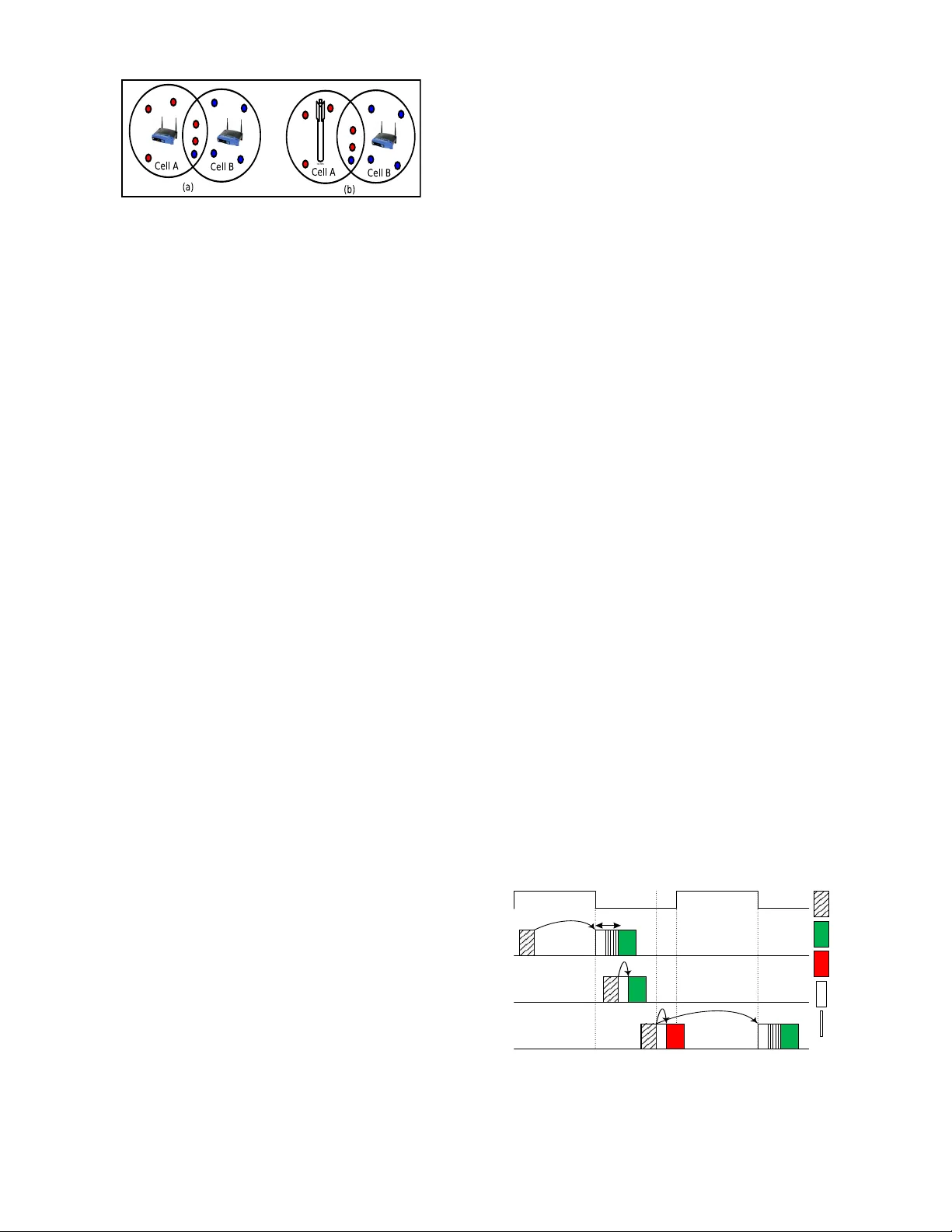
Association fairness in W i-Fi and L TE-U coe xistence V anlin Sathya † , Morteza Mehrnoush ∗ , Monisha Ghosh † , and Sumit Roy ∗ † Univ ersity of Chicago, Illinois, USA. ∗ Univ ersity of W ashington, Seattle, USA. Email: vanlin@uchicago.edu, mortezam@uw .edu, monisha@uchicago.edu, sroy@u.washington.edu. Abstract —In this paper we addr ess the issue of association fairness when Wi-Fi and L TE unlicensed (L TE-U) coexist on the same channel in the unlicensed 5 GHz band. Since beacon transmission is the first step in starting the association process in Wi-Fi, we define association fairness as how fair L TE-U is in allowing Wi-Fi to start transmitting beacons on a channel that it occupies with a very large duty cycle. According to the L TE-U specification, if a L TE-U base station determines that a channel is vacant, it can transmit for up to 20 ms and turn OFF for only 1 ms, r esulting in a duty cycle of 95%. In an area with heavy spectrum usage, there will be cases when a Wi-Fi access point wishes to share the same channel, as it does today with Wi-Fi. W e study , both theoretically and experimentally , the effect that such a large L TE-U duty cycle can have on the association process, specifically Wi-Fi beacon transmission and reception. W e demonstrate via an experimental set-up using National Instrument (NI) USRPs that a significant percentage of Wi-Fi beacons will either not be transmitted in a timely fashion or will not be received at the L TE-U BS thus making it difficult for the L TE-U BS to adapt its duty cycle in response to the Wi-Fi usage. Our experimental results corroborate our theoretical analysis. W e compare the results with Wi-Fi/Wi-Fi coexistence and demonstrate that L TE-U/Wi-Fi coexistence is not fair when it comes to initial association since there is a much larger percentage of beacon errors in the latter case. Hence, the results in the paper indicate that in order to maintain association fair ness, a L TE-U BS should not transmit at such high duty cycles, even if it deems the channel to be vacant. I . I N T R O D U C TI O N Driv en by increasing user demands for greater bandwidth and limited licensed spectrum, cellular systems will soon be deployed in the 5 GHz unlicensed bands, which are primarily used by W i-Fi today . T wo systems are under consideration for this deployment: (i) L TE-LAA [1], [2], which is being dev eloped by the 3GPP standardization body and uses listen- before-talk (LBT), which is similar to carrier sense multiple access with collision av oidance (CSMA/CA) used by W i-Fi and (ii) L TE unlicensed (L TE-U [3], [4]), which is being dev eloped by an industry consortium (L TE-U Forum) and employs a much simpler, b ut potentially more harmful to Wi- Fi, coexistence mechanism which depends on duty-cycling along with a “light” sensing technique called Carrier Sense Adaptiv e Transmission (CSA T) that adapts the duty cycle depending on the perceiv ed Wi-Fi usage at the L TE-U base station (BS). In this paper we focus on L TE-U in the following specific scenario: according to the L TE-U specification, if a channel is “v acant”, i.e. no Wi-Fi is detected, a L TE-U BS can transmit for a maximum 20 ms ON time and a minimum 1 ms OFF time thus leading to a 95% duty cycle [5]. If a W i-Fi access point (AP) now wishes to also share this channel with L TE-U, it has to begin by transmitting beacons, which are also subject to CSMA/CA. Howe ver with such a large duty cycle, and only 1 ms of OFF time, it is unclear as to ho w successful it will be in setting up its beacon transmissions, which is a necessary prerequisite before association with other W i-Fi devices can take place. W e call this criterion association fairness , to distinguish it from thr oughput fairness in which the L TE-U and W i-Fi share the channel fairly to achiev e the same system throughput. While there have been a number of papers in vestigating thr oughput fairness as a function of detection threshold and duty-cycle when Wi-Fi and L TE-U coexist [6]–[9], this particular issue of association fairness has not receiv ed much attention. In [10], an initial inv estigation by Google into the issue of coexistence between L TE-U and W i-Fi is summarized. L TE- U can lead to long consecuti ve strings of missed beacons for W i-Fi clients that giv e up on beacon reception after some pre- defined time, thus making dis-association even more likely than the a verage beacon delay time indicates. The association fairness problem is briefly described in this paper , but a comprehensiv e data analysis is missing. In this paper, we study specifically the association fairness issue theoretically as well as with an experimental test-bed using National Instrument (NI) USRPs that transmit a L TE- U signal, real Wi-Fi APs and laptops with Wireshark [11] installed to capture beacon transmissions and receptions, with the goal of quantifying the ef fect of L TE-U duty cycle and OFF time on W i-Fi beacon transmission and reception. The beacon drop probability and expected deliv ery time is modeled analytically and corroborated via NI experimental testbed for validating the results. Our results indicate that ev en when the channel is not occupied by a W i-Fi AP , L TE-U should not use its maximum allowed duty cycle of 95% in order to allow W i-Fi APs to begin the association for sharing the channel. I I . B AC K G RO U N D In this section, we present the system model that we consider in this paper , a brief background on Wi-Fi beacon transmissions and the L TE-U signaling scheme. A. Coe xistence System Model W e consider L TE-U/Wi-Fi coexistence in the unlicensed 5 GHz band. The L TE-U transmissions in the unlicensed band are only on the downlink, with all uplink traffic (acknowledge- ments and control) being transmitted on a licensed channel. W e will compare a L TE-U/W i-Fi coexistence scenario with a Fig. 1: (a) Cell A and Cell B use W i-Fi, and (b) Cell A switches to L TE-U W i-Fi/W i-Fi coexistence scenario to ev aluate the association fairness in the two cases. Figure 1 (a) sho ws the deployment configuration being considered with both Cell A and Cell B using Wi-Fi, where the users associated with Cell A and Cell B are denoted by red and blue respectiv ely . Figure 1 (b) shows Cell A switching to L TE-U. W e will ev aluate the association issue by v arying the duty cycle for the L TE-U transmission and examining the ef fect on W i-Fi beacon transmission and reception. B. W i-F i Association pr ocess W i-Fi allows two kinds of beacon scanning: passiv e and activ e. In passive scanning, the W i-Fi client passi vely listens to a beacon transmission from the AP . When it is successfully receiv ed, the client gathers the BSS information and initiates the association process with the AP . In acti ve scanning, the client actively requests a beacon by broadcasting a probe request packet. The AP then replies to the client by sending a probe response packet ( i.e., unicast packet) which is similar to a beacon packet. Most W i-Fi APs support both activ e and passiv e scanning modes, i.e. both beacon and probe response packets are transmitted by the AP during the association process. In this paper we analyze passive scanning only , which depends on reliable transmission and reception of beacon frames. C. W i-F i Beacon transmission T o announce its presence a W i-Fi AP periodically transmits beacon frames. The beacon frame consists of the service set identifier (SSID) which is used to identify its infrastructure basic service set (BSS), and its netw ork capability information. Other information sent in a beacon frame includes time stamp, beacon interval, supported data rates, traffic indication map (TIM), BSS load, QoS capability , etc. Beacon frames are sent periodically at an interval defined in T ime Units (TU), which is typically configured in the AP as 100 TU (102.4 ms). The size of a beacon frame varies from 60 to 450 bytes, depending on the information being transmitted. Beacon frames are also transmitted with CSMA/CA [12], i.e. the AP needs to check for the av ailability of the channel before sending beacon packets. If the channel is sensed to be idle, the AP will perform a random back-off with the minimum contention window (CWmin). During back-off, if the channel is sensed to be busy , the AP defers until the channel is again sensed to be idle. Since there is no acknowledgment (A CK) in beacon transmissions, the AP just selects the random back-of f based on CWmin. If the beacon packet is transmitted, b ut not receiv ed at a particular location, it will not be re-transmitted because it is a broadcast packet and there is no A CK. D. L TE-U L TE-U uses the basic L TE frame structure, i.e. a frame length of 10 ms. There is no LBT or CSMA/CA employed be- fore e very data transmission. Instead, a duty-cycling approach is used where the duty cycle is determined by percei ved W i- Fi usage at the L TE-U BS, using carrier sensing. If a single W i-Fi AP is detected, the duty cycle is set at 50%. Once the duty cycle is set, the L TE-U BS is allowed to transmit data ov er the unlicensed channel during the ON state without LBT . Con versely , the L TE-U BS is expected to not operate on the unlicensed channel during the OFF state. According to the L TE-U Forum specification, the duration of ON state should be more than 4 ms and less than 20 ms. Also, the duration of the OFF state should be at least 1 ms. Hence, if no activ e W i- Fi AP is detected, a L TE-U BS can start transmissions with a ON time of 20 ms and a OFF time of 1 ms, resulting in a duty cycle of 95%. During the ON period, downlink transmissions to UEs are scheduled by the L TE-U BS, unlike W i-Fi where each transmission has to be preceded by a CSMA/CA process. E. Association Pr ocess in L TE-U W i-F i Coe xistence The beacon transmission and reception process in L TE- U/W i-Fi coexistence is illustrated in Figure 2 with an example L TE-U duty c ycle of 50%. In Case 1, the beacon is generated during the L TE-U ON period, with a periodicity determined by the AP with a nominal value of 102.4 ms. Since the channel is busy due to the L TE-U ON time, the Wi-Fi AP waits until the end of the ON period, senses the channel for a time equal to DCF interframe space (DIFS), selects a random back-of f and transmits the beacon if the channel is idle. Since the minimum length of the OFF period is 1 ms which is larger than the beacon transmission time of 427 µs as gi ven in T able I plus the DIFS and back-off time, overlap with the second ON period does not happen and the beacon is transmitted and received successfully . In Case 2, the beacon is generated during the L TE-U OFF period, the channel is idle, the AP performs DIFS, then random back-off and transmits. In this case also the beacon transmission time plus DIFS, and back-of f time is such that the beacon does not overlap with the second ON period and the beacon is transmitted and receiv ed successfully . In Case 3, the DIFS and backoff LTE-U ON LTE-U OFF Case 1 Case 2 Case 3 Beacon Generated Beacon Transmitted Beacon Dropped T ON T OFF a b DIFS backoff Fig. 2: Possible cases for beacon transmission and reception during one ON/OFF L TE-U cycle beacon is generated in the L TE-U OFF period and the DIFS sensing shows that the channel is idle. Now , two situations are possible: (a) the random back-off reaches zero and the AP transmits the beacon b ut partially or completely ov erlaps with the subsequent L TE-U ON period, or (b) before finishing the random back-off the subsequent L TE-U ON period starts which causes the AP to wait till the end of the L TE-U ON period and continue the back-off afterwards. The length of the beacon transmission time is smaller than the minimum OFF period (1 ms), so the generated beacon generally is either transmitted in the current period or differed to the start of the next OFF period. In Case 1 and Case 3b above, the nominal inter-beacon transmission interval of 102.4 ms will increase and in Case 3a, the beacon will be transmitted b ut may not be receiv ed successfully since while some errors in the beacon frame can be corrected by the error correction coding, if a sufficiently large portion of the beacon frame is interfered with by the L TE-U transmission, it will not be received correctly . Our theoretical analysis and experimental study will quantify both these types of ev ents as a function of duty cycle and period. The abov e cases assumed that during the association process only beacons were being transmitted (no data or other associa- tion frames), but as explained in Section II-B most W i-Fi APs will respond to probe requests from clients with a probe re- sponse, which is an unicast packet with a corresponding ACK. If the probe response transmission is unsuccessful, the AP will double its contention windo w on the next transmission. These packets will also be transmitted during the L TE-U OFF period and hence will hav e an impact on beacon frame transmission and reception as well. T ABLE I: Beacons T ransmission Parameters Parameter V alue W i-Fi mode IEEE 802.11 ac DIFS 34 µs CWmin (W) 16 Beacon Frame Length 305 bytes Beacon T ransmission Data Rate 6 Mbps Beacon transmission time ( T b ) 427 µs PHY preamble 20 µs T ime slot ( t s ) 9 µs For comparison with the abov e, let us consider the case of W i-Fi/W i-Fi coexistence. Assume that there is a single W i-Fi AP on a channel with fully loaded traffic: this is analogous to the case we will consider later with L TE-U using a 95% duty cycle. If a second W i-Fi AP wishes to use this channel, perhaps because no other vacant channel is av ailable for its use, it will commence by transmitting beacon frames advertising its presence. Since both Wi-Fi APs use CSMA/CA on beacon and data frames, the new AP will be able to access the channel fairly and begin transmitting beacons successfully . This is in contrast to the situation described above with L TE-U/W i-Fi coexistence where beacons can get delayed or not receiv ed correctly , especially with a duty cycle of 95% where the second Wi-Fi AP will initially hav e e xtremely limited access to start transmitting beacons since L TE-U does not back- off. There is a chicken and egg problem here in that L TE- U is supposed to reduce its duty-cycle when it detects Wi- Fi, but if W i-Fi is unable to ev en start transmitting beacons, how will L TE-U detect Wi-Fi and scale back its duty cycle appropriately? I I I . B E A C O N D RO P P RO B A B I L I T Y In this section, we calculate the beacon drop probability of W i-Fi when it coexists with L TE-U to in vestigate how L TE- U affects the beacon frame transmission. W e assume that the W i-Fi and L TE-U are co-channel and that all W i-Fi stations (AP and clients) can perfectly detect the L TE-U in the ON period. As mentioned previously , beacon transmission follows the CSMA/CA protocol, ho we ver since it is a broadcast packet, there is no A CK and the random back-of f is selected based on the minimum contention window (CWmin). The main reason that a W i-Fi beacon once transmitted is not recei ved is that the beacon frame overlaps with the L TE-U ON period after transmission. T o calculate the drop probability we consider Case 3a in Figure 2. W e assume that if more than P o % of the beacon frame overlaps the subsequent L TE-U ON period, i.e. d P o T b /t s e time slots of the beacon frame overlap with second ON period where t s is slot time and T b is the beacon transmission time, the beacon would be dropped. This means that less than P o % ov erlap could be potentially corrected by the error correcting code. The probability that a beacon is generated at a time slot in the OFF period is: P s = P ( O F F ) P ( t s | O F F ) = T OF F T ON + T OF F × t s T OF F = t s T ON + T OF F , (1) where T ON is the L TE-U ON, and T OF F is L TE-U OFF period. So, the beacon drop probability given the beacon transmission time and minimum overlap which causes the beacon to drop is calculated as: P dt = P s ( d (1 − P o ) T b /t s e ) . (2) From eq (2), we see that the drop probability is independent of the L TE-U duty cycle and depends only on the total length of one ON/OFF period i.e. the number of ON/OFF cycles which happen in one 102.4 ms beacon period or equiv alently the number of ON edges in a 102.4 ms period. I V . A D D I T I O N A L E X P E C T E D D E L I V E RY T I M E C A L C U L A T I O N In this section, the beacon deli very time of W i-Fi in coe x- istence with L TE-U is analyzed for both theoretical analysis and experimental calculation to in vestig ate how the L TE-U duty cycle af fects the W i-Fi beacon transmission. A. Theor etical Analysis T o calculate the additional expected beacon deli very time of the beacon (this is the additional expected time from the beacon generation until the successful delivery time when coexisting with L TE-U), we hav e to capture the expected delay of Case 1, Case 2 and Case 3b in Fig. 2. The expected delay of beacon deliv ery in Case 1 is: E [ T 1 ] = T ON / 2 + DIFS + W − 1 2 t s + T b , (3) where the term T ON / 2 is the expected delay assuming the beacon generation in the L TE-U ON period follows the uni- form distribution. The expected delay of beacon delivery in Case 2 is: E [ T 2 ] = DIFS + T b . (4) Similarly the expected delay of beacon deli very in Case 3b is: E [ T 3 ] = DIFS / 2 + T ON + DIFS + W − 1 2 t s + T b , (5) where the term DIFS / 2 is the expected delay because the L TE- U ON starts in the DIFS sensing period. The total expected deliv ery time (in case the beacon is not dropped) is: E [ T bt ] = P b E [ T 1 ] + (1 − P b ) × T OF F − ( T b + DIFS ) T OF F E [ T 2 ] + DIFS T OF F E [ T 3 ] , (6) where the P b = T ON T ON + T OF F . In eq (6), the additional expected beacon deli very time directly depends on the L TE-U duty c ycle ( P b ) and the length of the ON period in each cycle ( T ON ) unlike the drop probability in eq. (2) which depends only on T ON . B. Experimental Calculation Let the W i-Fi beacon generation times be: b 1 , b 2 , b 3 , . . . , b N . Nominally these are 102.4 ms apart, i.e., b i +1 − b i = 102.4. W e cannot measure, experimentally , the actual beacon gener- ation times, b i . Howe v er , we can measure, using W ireshark, the beacon reception times: t 1 , t 2 , t 3 , . . . , t N . Let us assume there are no dropped beacons. The theoretical analysis giv es us an expression for E[ t i - b i ] in eq. (6), which experimentally can be calculated as follows. 1 N N X i =1 ( t i − b i ) = 1 N [ N X i =1 t i ] − 1 N [ N X i =1 ( b 1 + 102 . 4( i − 1))] = 1 N [ N X i =1 t i ] − b 1 − 102 . 4 N − 1 2 (7) Hence, in order to match the experimental results with theory , we need to estimate the initial condition, which is the beacon generation time of the first beacon, b 1 . W e will describe in the next section ho w we can do so experimentally . V . E X P E R I M E N TA L R E S U L T S A N D A N A L Y S I S In this section, we first describe the experimental setup, followed by validation of the theoretical results from the previous section with careful experiments. The objective here is to accurately determine the number of successful W i-Fi beacon transmissions and receptions for dif ferent duty cycles and OFF periods of the L TE-U so that we can characterize the association scenarios described in Section II.E. above. Fig. 3: L TE W i-Fi Co-existence Experimental Setup. T ABLE II: Simulation parameters Parameter V alue T ransmission Scheme OFDM Bandwidth 20 MHz Operating frequency 5.805 GHz Operating channel 161 T ransmission power for both L TE and W i-Fi 23 dBm T raffic Full Buffer (Saturation Case) T ransmission time interval 1 ms T ime slot duration ( t s ) 9 µs W i-Fi Energy Threshold -82 dBm Beacon transmission interval 102.4 ms W i-Fi sensing protocol CSMA/CA W i-Fi Antenna T ype MIMO L TE-U Antenna T ype SISO L TE-U ON/OFF period 20 ms ON/OFF , 5 ms ON/OFF , 20 ms ON & 5 ms OFF and 20 ms ON & 1 ms OFF L TE-U data and control channel PDCCH and PDSCH A. Experimental Setup The coexistence system model described in Section II is tested using a set-up based on a NI USRP and off-the-shelf W i-Fi APs and client de vices. The experiment was set up in an open lab environment where there are other W i-Fi clients in the area that may be transmitting probe requests to the APs under test. W e use the L TE coexistence framew ork [13] and configure the NI USRP 2953R SDR to transmit a L TE-U signal and v ary the ON and OFF times to obtain dif ferent duty c ycles. T wo Netgear APs are used as the W i-Fi APs. Figure 3 shows the experimental test-bed setup where Cell A is either the L TE- U BS or a W i-Fi AP labeled as “Experiment AP” and Cell B is always Wi-Fi and is labeled “Coexistence AP”. Cell B does not transmit any data, only transmits beacon frames (and probe responses, if clients in the vicinity transmit probe requests). The W i-Fi APs and the NI L TE-U BS are provisioned to operate on the same unlicensed channel (Channel 161), and it was ensured that there are no other W i-Fi APs on this channel. Since the NI L TE-U BS implementation does not implement CSA T , we measure ho w many Wi-Fi beacons are receiv ed at the L TE-U BS by using a laptop in monitor mode with W ireshark installed on it and placing it v ery close to the L TE-U BS. W e will call the beacons received by this laptop as “W i-Fi beacons receiv ed at Cell A ”. W e also use W ireshark on another laptop in monitor mode at the same time near the transmitting W i-Fi AP (Cell B), and call the beacons recei ved by this laptop as “W i-Fi beacons transmitted by Cell B”. By comparing the sequence IDs of each beacon that is reported by the Wireshark at each laptop, we can compare how many beacons were successfully transmitted (from the laptop close to the W i-Fi AP at Cell B) and received (from the laptop close to the Cell A). The L TE-U and W i-Fi transmission characteristics and other parameters under study are summarized in T able II. W e study W i-Fi/W i-Fi coexistence and L TE-U/W i-Fi coexistence under different scenarios described below . B. Theor etical Results and Comparison for Beacon Reception In this section we present experimental validation of the theoretical analysis of the beacon drop probability dev eloped in Section III. In real deployments, most W i-Fi APs support both acti ve and passive scanning modes, i.e., both beacon and probe response packets are transmitted by the AP during the association process. Howe ver , the generation of probe request packets (randomly broadcast by the W i-Fi clients) is dif ficult to model theoretically . Hence, in order to verify the theoretical analysis, we disable 1 the probe request packet for this particu- lar experiment. The experimental result is calculated based on the number of received beacon packets out of 3000 transmitted packets, where the distance between the Wi-Fi AP and L TE-U is 17 feet and the Wi-Fi client is close to the AP . Using the beacon parameters in T able I and P o = 0% ov erlap, i.e. any ov erlap with a L TE-U ON period results in a beacon drop, the successful beacon reception probability (which is 1 − P dt ) is shown in the theoretical column of T able III. There is good agreement between the theory and the experiment, both of which demonstrate that the beacon drop probability is a function of the total period of one ON/OFF cycle of the L TE-U transmission. T ABLE III: Theoretical and experimental Beacon Reception Setup Theoretical Experimental T ON = T OF F = 5ms 0.9559 0.9626 T ON = 20ms, T OF F = 1ms 0.9794 0.9656 T ON = T OF F = 20ms 0.9892 0.9700 C. Theor etical Results and Comparison for Beacon Delivery T ime In this section we present experimental and theoretical expected deli very times as calculated in Section IV . T able IV shows the theoretical expected deliv ery time as calculated from eq. (6) and the experimental expected time of the beacon using eq. (7). In order to estimate the generation time of the first beacon b 1 , we set up an e xperiment where the W i-Fi AP begins transmitting beacons on a clean channel i.e., with no L TE-U or other interference, thus ensuring that the measured received time t i is approximately equal to the beacon transmitted time b i . This giv es a reference for b 1 . W e then turn on the L TE- U, and start measuring t i again. W e use these measurements in eq. (7) to calculate the experimental v alues in T able IV. W e observe that L TE-U with 20 ms ON/1 ms OFF causes the highest expected deli very time; while 5 ms ON/5ms OFF causes the smallest delay and that the ov erall trends remains the same in both theory and experiments. T ABLE IV: Theoretical and experimental expected deli very time of the beacon. Setup Theoretical Experimental T ON = T OF F = 5ms 1.82 ms 1.01 ms T ON = 20ms, T OF F = 1ms 10.15 ms 7.42 ms T ON = T OF F = 20ms 5.59 ms 4.24 ms D. P erformance comparison with LTE-U duty cycle of 95% In this section we study the coexistence performance with a baseline experiment with a L TE-U duty cycle of 95%, i.e. 20 ms ON/1 ms OFF as follows. 1 In order to turn off the probe request packets, we carried out the experiment late at night on the University of Chicago campus and verified from Wireshark that no probe request packets were generated. • Step 1: Only one W i-Fi AP is deployed, Cell B in Figure 3. • Step 2: W i-Fi/W i-Fi coexistence: both Cell A and Cell B use W i-Fi. • Step 3: L TE-U/W i-Fi coexistence: Cell A switches to L TE-U and Cell B continues using W i-Fi. 0 0.2 0.4 0.6 0.8 1 0 0.5 1 1.5 2 2.5 3 Cumulative Distribution Function (CDF) Inter-beacon Interval (in seconds) Step 1 Step 2 Step 3 Fig. 4: CDF of beacon interval for Steps 1, 2 and 3 Figure 4 sho ws the CDF of the inter-beacon interval when the two cells are separated by a distance of 17 feet. At this distance, there are no hidden-node issues to contend with. The inter-beacon time interval, should be close to 102.4 ms. But due to L TE-U interference, we see that in Step 3, this interval can be as large as 3 ms, which will have a significant effect on how long it takes for the L TE-U BS to detect the presence of the W i-Fi AP . On the other hand, there is no perceptible difference in the inter -beacon times between a single W i-Fi (Step 1) and two coexisting Wi-Fi APs (Step 2). Hence it is clear that L TE-U on an empty channel does not coexist with another W i-Fi that wishes to share the channel in the same way that Wi-Fi coexists with Wi-Fi in the same situation with respect to beacon reception. W e performed the e xperiment at different inter -cell distances and observed similar performance, which are not included due to space limitations. E. Comparison with differ ent LTE-U duty cycles and periods In the baseline comparison in the previous section, we only looked at the received beacons for a single duty cycle of 95%. In this section we examine performance with different duty cycles and periods. W e will consider the following cases: • Case A: W i-Fi/W i-Fi Coexistence. • Case B: L TE-U/Wi-Fi Coexistence with 5 ms ON/5 ms OFF L TE-U duty cycle. • Case C: L TE-U/W i-Fi Coexistence with 20 ms ON/20 ms OFF L TE-U duty cycle. • Case D: L TE-U/W i-Fi Coexistence with 20 ms ON/1 ms OFF L TE-U duty cycle. • Case E: L TE-U/W i-Fi Coexistence with 20 ms ON/5 ms OFF L TE-U duty cycle. In all cases abov e, beacon transmissions, receptions and inter-beacon interval measurements were made over a period of 5 mins, during which 3000 beacons should be transmitted. Beacons are transmitted by the 00 Coexistence AP 00 in Cell B and are received at the L TE-U BS in Cell A, 17 feet away as 0 0.2 0.4 0.6 0.8 1 0.05 0.1 0.15 0.2 0.25 0.3 0.35 0.4 0.45 Cumulative Distribution Function (CDF) Inter-beacon Interval (in seconds) CASE A CASE B CASE C CASE D CASE E 0 0.2 0.4 0.6 0.8 1 0 0.5 1 1.5 2 2.5 3 Cumulative Distribution Function (CDF) Inter-beacon Interval (in seconds) CASE A CASE B CASE C CASE D CASE E Fig. 5: (a) CDF of transmitted beacon interv als and (b) CDF of received beacon intervals 0 1000 2000 3000 4000 5000 Case A Case B Case C Case D Case E Number of Beacons Coexistence Mode Wi-Fi Beacons Expected Wi-Fi Beacons Transmitted by Cell B, Coexistence AP Wi-Fi Beacons Received at Cell A Fig. 6: Beacons Reception at different ON/OFF modes. shown in Figure 3. Figures. 5 (a) and 5 (b) show the CDF of transmitted beacon interval and recei ved beacon interval respectiv ely . W e see that the transmitted and received beacon interval increases in Case D considerably , compared to the other scenarios, with the received beacon interv al e xtending to seconds in some cases. Figure 6 shows the total number of e xpected beacons, trans- mitted beacons and receiv ed beacons for the fi ve cases abov e. In Case A, W i-Fi/W i-Fi coexistence, there is no appreciable drop in the number of beacons received. Howe ver in all of the other cases of L TE-U/Wi-Fi coexistence, there is a drop in the number of beacons receiv ed, ev en when the duty cycle is 50% (Case B and Case C). In Case D, 20 ms ON/1 ms OFF , almost 1/3 of the transmitted beacon frames are not receiv ed at the L TE-U BS. Interestingly , Case E, with 80% duty cycle has a similar beacon loss performance as Case B and C with 50% duty cycle. Hence, it may be advisable for a L TE-U BS to use a duty cycle of no greater than 80% in order to allo w a W i-Fi AP fair access to the medium. With 80% duty cycle, the reduction in the number of beacons that are not receiv ed at the L TE-BS will also enable the L TE-U BS to react faster to the presence of W i-Fi by reducing its duty cycle to the required 50%. V I . C O N C L U S I O N S A N D F U T U R E W O R K In this paper , we performed theoretical analyses and exten- siv e measurements with Wi-Fi and L TE-U in realistic deploy- ments to understand the W i-Fi beacon transmission/reception behavior when L TE-U operates on the same channel. W e hav e shown very good agreement between the analyses and measurements. The motiv ation is to understand if L TE-U should be operating with its maximum allowed duty cycle of 95% when it is operating on an empty channel. W e find that if it does so, it will severely impact the ability of a Wi-Fi AP to share the channel since the beacon transmission/reception will be disrupted. Instead, if L TE-U scaled back the occupancy on an empty channel to 80% (i.e. 20 ms ON/5 ms OFF), the W i-Fi beacon loss reduces to an acceptable level and makes it easier for W i-Fi to get on the air . Our work did not have a CSA T algorithm that would automatically detect W i-Fi and scale back the duty cycle automatically . Future work will implement a realistic CSA T algorithm on the NI USRP and e valuate the performance. This work was supported by NSF under grant CNS- 1618920. R E F E R E N C E S [1] “3GPP Release 13 Specification, 2015. ” http://www .3gpp.org/rele- 13/. [2] A. V . Kini, M. Hosseinian, M. Rudolf, J. Stern-Berkowitz, et al. , “Wi- Fi-LAA coexistence: Design and evaluation of Listen Before T alk for LAA, ” in CISS , pp. 157–162, IEEE, 2016. [3] “L TE-U Forum. ” http://www .lteuforum.or g. [4] Y . Pang, A. Babaei, J. Andreoli-Fang, and B. Hamzeh, “W i-Fi Coexis- tence with Duty Cycled L TE-U, ” W ir eless Communications and Mobile Computing, Hindawi , pp. 1–10, Jan 2017. [5] “L TE-U Forum, ”L TE-U CSA T Procedure TS V1.0”. ” 2015. [6] C. Cano and D. J. Leith, “Unlicensed lte/wifi coexistence: Is lbt inherently fairer than csat?, ” in ICC , pp. 1–6, IEEE, 2016. [7] E. Chai, K. Sundaresan, M. A. Khojastepour , and S. Rangarajan, “L TE in unlicensed spectrum: are we there yet?, ” in Pr oceedings of the 22nd Annual International Conference on Mobile Computing and Networking , pp. 135–148, A CM, 2016. [8] E. Almeida, A. M. Cavalcante, R. C. Pai va, F . S. Cha ves, F . M. Abinader , R. D. V ieira, S. Choudhury , E. Tuomaala, and K. Doppler , “Enabling L TE/W iFi coexistence by L TE blank subframe allocation, ” in IEEE ICC , pp. 5083–5088, Nov . 2013. [9] Q. Chen, G. Y u, and Z. Ding, “Optimizing Unlicensed Spectrum Sharing for L TE-U and W iFi Network Coexistence, ” IEEE Journal on Selected Ar eas in Communications , vol. 34, no. 10, pp. 2562–2574, 2016. [10] N. Jindal, D. Breslin and A. Norman, “L TE-U and W iFi: A Coexistence Study , White Paper, ” in https://ecfsapi.fcc.gov/file/60001078145.pdf . [11] “W ireshark. ” http://www .wireshark.org/. [12] “W ireless LAN Medium Access Control (MAC) and Physical Layer (PHY) specifications, ” IEEE Std 802.11-2012 , 2012. [13] National Instruments, “Real-time L TE/Wi-Fi Coexistence T estbed, ” in http://www .ni.com/white-paper/53044/en/ , Feb 2016.
Original Paper
Loading high-quality paper...
Comments & Academic Discussion
Loading comments...
Leave a Comment