Reconfigurable Digital Channelizer Design Using Factored Markov Decision Processes
In this work, a novel digital channelizer design is developed through the use of a compact, system-level modeling approach. The model efficiently captures key properties of a digital channelizer system and its time-varying operation. The model applie…
Authors: A. Sapio, L. Li, J. Wu
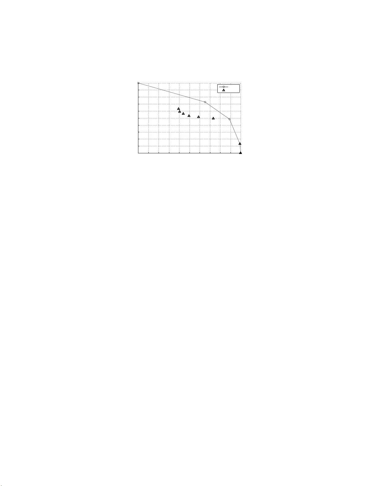
Reconfigu rable Digital Channeliz er Design Usi n g Factored Markov Decision Processes Adrian Sapio 1 asapio@umd. edu Lin Li 1 lli12311@um d.edu Jiahao W u 1 jiahao@umd. edu Marilyn W olf 2 wolf@ece.ga tech.edu Shuvra S. Bhattacharyya 1 , 3 ssb@umd.edu 1 Univ ersity of Maryland, College P ark, Maryland, USA 2 Geor gia Instit ute of T echnology , Geor gia, USA 3 T ampere Univ ersity of T echnology , Finland Abstract In this work, a nov el digital channelizer design is de veloped through the use of a compact, system-lev el modeling approach. The model ef ficiently captures ke y properties of a digital ch annelizer system and its time-v arying operation. The model app lies po werful M arko v Decision Process (MDP) techniques in new ways for design optimization of reconfigurable channelization processing. The result is a promising methodology for design and implementation of digital chan nel- izers that adapt dynamically to changing use cases and stochastic en vironments while optimizing simultane ously for mu ltiple co nflicting performance go als. The method is used to employ an MDP to generate a runtime reconfiguration policy for a time-v arying en vironment. T hrough extensi ve simulations, the r obustness of the adaptation is demonstrated in comparison with the prior state of the art. 1 Introd uction Digital channelizers are critical subsystems in wireless commun ication systems that are employed when a multiplexed signal contains inform ation in different fr e quency subband s, and the application requires sep arating on e inp ut signal (containin g multi- ple subbands) into one or more outpu t signals (eac h co ntaining a sub set of the input subband s) [22]. This function is comm only r equired in cogn iti ve radio systems [7]. In this work, we seek to leverage th e reconfigu ration ca p abilities of moder n embed- ded p latforms to d ev elop digital channelizer s that can better adapt to the en vironmen t in which they are operating. Ad apting to the en vironmen t using an effecti ve system-level r eco nfigu ration framework ( SLRF ) can help the se systems ope rate more effecti vely — e.g., with improved tra d e-offs am ong achiev able data rate, latency , an d energy effi- ciency . For this purpose, we apply Markov Decision Processes (MDPs) in n ovel ways This article has been accep ted for pub lication in a future issue of the Journal of Signal Processing Systems, but has not been fully edited . Content may change prior to final publicatio n. to m ake dyna mic decisions o n m aintaining or adapting sign al p rocessing con figuration s during ch annelizer oper a tion. W e propo se an MDP-ba sed SLRF to d ev elop dynamic reconfigu ration po licies for use in stochastic environments in which adap tatio n of h a r d- ware/software con figuration s for digital chann elizer p rocessing is strategic. While the SLRF tech niques are dev eloped in this paper with a specialized focus on dig ital chann elizer implementa tio n, we believe th at the underly in g MDP techniq ues are app licable acro ss many oth er typ es of embedded signal processing systems (ESI Ps). Explorin g the gener alization of our SLRF f or br oader classes of ESIPs is therefo r e a useful direction for futu re work . Our MDP-based ap p roach for digital channelizer design optimizatio n r esults in in- creased robustness when used to period ically re- optimize th e system policy spe c ifica lly for the external en v ironmen t it is being used in. This periodic re-optimization can be done completely a utonom ously by an embed d ed signal processor, without any need for hum an-in-th e -loop intervention. The inf o rmation our design op timization methods require is comp letely obser vable by the system at r untime. The rem ainder of the pap er is organized as follows. W e provide a cursor y revie w of the history of chann e lize rs and MDPs, an d their d ev elopment in Section 2. In Section 3, we detail the si gnal processing application and the algorithms inv olved. In Section 4, we introduce o ur MDP-based a p proach an d illustrate how it is applied to the signal processing application. W e follow th at in Section 5 with a summary of the simulations perfor med and the resultin g data and o bservations that were m ade. W e conclude in Section 6 with a discu ssion o f f uture work on the use of MDPs in channelizers. 2 Backgrou nd and Related W ork A digital chann elizer can b e gener a lized as h aving the inp uts and outputs shown in Figure 1. W ithout lo ss of generality , we r epresent the inputs an d outputs as frame- based vector quantities, with time decomposed into fixed-width slots referred to as frames . The frame ar r iv al rate is co nstant and the stream of incoming frames is never ending. A channelizer is of ten a su bsystem of a larger signal pro cessing system. For each fr ame of d ata, the chan nelizer is commanded by hig her-le vel elements of th e larger signal pr o cessing system on a per -frame ba sis. T hese high er lev el elem ents deter m ine which sub-chann els ne e d to b e pro duced and wh ich do not. An example of such a chann elizer framew o rk can be fo und in the co g nitive radio of [17]. In that applica tion, a ch annelizer is used to iso la te sub-bands within some wireless spectru m dyna m ically . This dy namic behavior in volves consuming a wide- band signal, and app ly ing digital filters an d rate-ch anging operations to p roduce an output that contains some subset o f the input signal frequ e ncies. In Figure 1, for each fram e n of d ata, x ( n ) is a length N co mplex vector of the wideband input sign al. This data is presented to the channelizer alo ngside CR ( n ) , a length N C binary vector that p rovides the chan n elization r equest fo r that frame. The channelizer outputs N C parallel outpu t d ata vectors, y α ( n ) , α = { 1 , 2 , . . . , N C } . (1) Each of these vectors conta in s a channelized subset of th e in p ut. 2 ∈ 0,1 ∈ ∈ / ∈ / ∈ / Channelization Request W id eband Input Channelized Outp uts Figure 1: Cha n nelizer inputs and outpu ts. Good surveys of popular digital channelizer architectur es to date are found in [ 16, 2 2, 25]. The most com mon arch itectures are based on the Cosine Mod ulated Fil- ter Ban k (CMFB ), Discrete Fourier Transform Filter Bank (DFTFB) and Per-Channel Filter Bank (PCFB). Aside from th ese well-established architectu res, sev eral o ther in- teresting designs for app lica tion-specific c h annelizers can be fou nd in [1 3, 14, 9, 10]. As illustrated in [ 7, 1], the channelizer is of ten one of the most com putationa lly in - tensiv e and power co nsuming b lo cks o f cogn itiv e radio tr a nsceiv ers, mainly d ue to its need to ru n at the highe st da ta r ates. For th is reason, s ev eral researchers hav e sought to create ch annelizer d esigns where the key parameters that co ntrol the pro- cessing (e.g., filter co e fficients, data rates, and sub channe l masks) are configu rable at run-time [5, 6, 8]. W e refer to th is class of DSP systems a s “reconfigur able chan neliz- ers”, and p oint to this active b ody of DSP researc h as evidence for the imp ortance of optimizing ch annelizer processing f o r exactly wh at is r equired , an d nothing mor e. The goal is generally to improve effi ciency by increa sing processing pro ductivity , while simultaneou sly decreasing energy co nsumptio n. The body o f prior work referen c ed above p rovides a number of ef ficient chan nelizer designs that c an be flexibly con figured for different trade-o ffs. Howe ver, this bod y of work do es n ot add ress how or when the con figurable param eters are changed, n or provide policies for changin g them at run-time. In this paper, we develop MDP-ba sed methods to bridge this gap . Other researcher s h av e sought to use MDPs with similar go als. W ei et al. h ave demonstra te d the ef f ectiv e use of an MDP to control the processing rate o f a network router [23]. This work created a Markov mod e l of only the external en vironmen t, not the system under contro l. In contra st, as described a bove, our prop osed SLRF incor- porates Markov mode ls of both the con trolled system and the external environment, which provides a m ore comp rehensive fo undatio n f or dyna mic ad aptation. Hsieh e t a l. [ 1 5] d evise a sch eduling p o licy that selects among alternative im ple- mentations of comm o n fu nctions, such as FFTs. The alternative options accomp lish function ally the same operation, but with different execution times, power deman ds, and hardware requ irements. As in o ur SLRF , Hsieh’ s appr oach u ses an algorithm to make recon fig uration d ecisions based on what requ ests are placed o n the system at runtime. Howe ver, in Hsieh’ s ap proach, th ese r e quests are converted to a time series signal, smoothed u sing a moving average filter, and then comp ared to thresho lds in order to derive reconfig u ration decisions. Th e d esigner must commit to a smoo thing 3 factor o n the inc o ming requests, a nd ef f ectiv ely assume a-prio ri some of the r esulting dynamics of the system. Compared to Hsieh’ s metho ds, our SLRF takes a v ery different approach by tran s- forming both the system and o perating environment into stoc hastic models, which can then be reason ed up on within the framework of MDPs. In contrast to th e ap proach of Hsieh, there are n o a-prior i trade-o ffs on the smo othing of in coming requests. Fur th er- more, instead of condensing th e o bservable data into on e - dimension al signals, larger condition al probab ility tables ar e m aintained. T hus, the algorith ms in our SLRF can incorpo rate more kn owledge into th e d ecision fr a m ew ork. By inco rporatin g h istorical transition p robab ilities, the MDP is able to infer in real-time whether a new request is likely to b e the start of an event that should b e acted upon, o r is more likely a spuri- ous request th a t is better ignored . This infere n ce can be perform ed immediately a n d without the delay associated with the step respo nse th rough a smooth ing filter . As described in Section 1, we app ly MDPs as a core part of our p r oposed methodol- ogy for r e configur able channe lizer design . A p r eliminary version of this work was pub - lished in [20]. This pre lim inary version built on the results of [ 2], where MDPs were demonstra te d to be useful tools for controllin g resources in com puting systems. In our preliminar y version [2 0], we intr oduced two in novations that significantly enhanced the effecti vene ss of MDPs for ch annelizer d e sign op timization. First, we added a mech- anism to add ress hard ware/software codesign scenarios that in volve multid imensional design objectives and constraints, which are c o mmon ly enco u ntered in tran sceiver sys- tem d esign. This was do ne thro ugh a multidimension al framework for th e d e finition of the MDP rewards functio n. Second, we introduced transition states in o ur MDP for mulation to represent inter- mediate states ( between distinct channelizer config urations) in the target system. W e applied transition states in scenarios where command ing a state chang e can result in one or mo re time steps (frames) where the system is in a non-p roductive transition mode. Since being in tran sition fro m on e state to ano ther can result in missing real- time d eadlines f o r pr o cessing req uests, th e c o ntrol policy must choose carefully when to comm and a tra n sition, and on ly seek to do so wh en the end r esult will be a net pos- iti ve for the system in the lon g run, in spite of any sho rt-term negativ e ef fects due to the transition frames. Such incorporation of tr ansition states within our SLRF extends its utility to a b roader class of applications, including chan nelizers, where tran sitions between p roduc ti ve states mu st be taken into account fo r ac curate assessment and op- timization o f dyn amic rec onfigur a tio n con trol. T o the best of o u r kn owledge, this was the first time that tran sition states and MDPs have been u sed together in this way in reconfigu rable embed ded system s. In this paper, we build on th e pr eliminary version [20] in three ways. First, we apply a m ethodolo gy dev eloped in [4] to transfo rm an MDP into a factor ed MDP . T h is concept addresses a problem that frequently occurs with M DPs — the number of possi- ble states of the m odel can b e extremely large. As detailed in [21], a m ajor motivation behind factored represen tations is that some par ts o f this large state space generally do not d e pend on each other an d that th is independ ence can be explo ited to derive a more c ompact rep resentation of the glo bal state. In ou r work, factorization ser ves to reduce the stora g e size of th e MDP model and execution time of the policy gene r ation algorithm s. Such advancements ar e critical enab le r s for a futu re direction of this work 4 — de p loying the mo deling framework and policy gen e ration algor ith ms to the targeted embedd e d system. Wh e n th e framew ork and algorithms ar e in tegrated with the ap p li- cation on th e embed ded platform, th ey can be u sed to perf orm periodic re-o ptimization of the reconfigur ation policies in addition to applyin g the policies to manage system configur ations. T o be practical in r esource co nstrained and po wer co nstrained em- bedded environments, the dep loye d implem entations of the modelin g fram ew ork and policy generation algorithms must be carefully optimized so that they consume mini- mal a m ounts o f storage and impose m inimal co mputation al burden. Our application of factored MDP techniques in this paper is an important step towards these objecti ves. Second, we detail the finding s of an expanded perform ance analysis of the p ro- posed metho dology . Specifically , we d escribe a suite o f comp eting control policies and compare them objectively with the MDP based techniques. T h e results show that the MDP based techniqu es ou tperfor m the alterna ti ve schemes in ne arly all cases. Third, we perform a trade- off analysis of the co sts and benefits of in c lu ding tran- sition states in the fr amew ork. This exploration d etails and quantifies th e design time modeling co sts o f transition states in both storage size an d execution time. These co sts are then contrasted with the ben e fits in the form of the ru n-time perform a nce when transition states a re include d versus wh en they are no t. While transition states we re introdu c ed in the pre liminary version [20] as a n ovel techniq ue for MDP-based design of reconfig urable emb edded systems, no experimen tal investigation of their associated trade-offs was p r ovided due to spac e limitations. In th is pap er , we p rovide a more complete presentation of transition states by de velop ing such an experim e n tal study . 3 Reconfigurable Channelizer Design In this section, we p resent a r econfigu rable digital ch annelizer design that f o rms the found ation for our MDP-based, adaptive c hannelizatio n system, which we presen t in Section 4, and demo n strate exp e r imentally in Sec tio n 5. Our c h annelizer system is implemented on the Silicon Lab s EFM32G G , a small and low power ARM Cortex M3-based micro controller . The p rocessor is ru nning on the EFM32 STK3700 dev elopmen t kit, which houses the CPU as well as sophisticated energy monitor ing circuitry . F or this hard ware, a ch annelizer width of N C = 8 sub- channels is used in an illu strativ e experim ent. This particular ch a nnelizer system is dev eloped with applicability to wireless sen- sor networks, which imp ose challenging constraints o n energy con sumption and re- source utilization. Howe ver, with its found ation in MDP techn iques, our design methodo logy is not specific to any particular d omain of channelization ap plications. For e xample, the methodolo gy can be adapted to large scale, high performance chan- nelization scenarios that inv o lve dozens or hundre ds of sub-chann els that r equire the use o f FP GAs or GPUs to run in rea l- time. Dev eloping such adaptation s fo r th ese ad - ditional classes of processing platfo rms is an inter esting area for future inv estigation. T o examine the ability of the system to adapt to its environment, we conside r two separate use cases, which w e refer to as A and B . Additionally , we cre a te mu ltiple scenarios within those use cases, by varying p arameters of the application that are un- derstood to be time-varying . W e design two separate chan nelizers, one ideally suited 5 z - 1 z - 1 M E 0 (z) M E 1 (z) M E M- 1 (z) Inverse DFT . . . . . . . . . Figure 2: DFTFB block diagram, M = N C . for each use case, as detailed in Section 3.1 and Section 3.2. W e then employ a recon - figuration p olicy derived using our SLRF with the decision-making author ity to select which chann e lizer alg o rithm to use at any given time. Additiona lly , the alg orithms contain configu ration parameters, and we giv e the SLRF control of these parameters. This resu lts in a unified con tr oller for reco nfiguratio n, dynamic power manag ement, and online param eter op tim ization. 3.1 Polyphase DFT Filter Bank Use Case A is the application in [17]. In that system, the requests are modeled as i.i.d. (in depend ent and identically distributed) Berno u lli across both the time a nd sub - channel dimension s. These statistics for the r e q uests mean that there is no opportun ity to anticipate the request vector . For such an environment, a sensible option is a filter bank that outpu ts all subchannels at all times, in the mo st efficient way po ssible. For this, we use a Poly phase implementation o f the canonical Discrete Fourier T ransfor m Filter Bank (DFTFB) describ ed in [22]. T o im p lement this DSP block, we begin by design ing a low pass filter to be u sed as the “prototype” filter in the filter b ank. The filter has a passband width of o ne eighth of the full spectru m , since there are e ig ht equally spaced chann els. The filter coefficients ar e chosen using the Equ iripple FIR design method detailed in [18]. The prototy p e filter is then shifted in freq u ency , decomp osed in to its p olyph a se compo nents E m ( z ) , and implemented in to th e DFTFB, as d e scribed in [2 2]. A block diagram of the derived DFTFB is shown in Figure 2. T he resulting m agnitud e re sponse for each of the 8 outputs is shown in Figure 3. As ca n be seen from the magnitud e respon ses of the 8 channe lize d o u tputs, this filter bank can simultaneously channelize all of the su b-chan n els, and thu s, we req uire no tunable param eters for this algorithm. In orde r to optimize f or b ursts of comm uni- cation activity as well as idle time, we give the co n troller the ability to p u t the DFTFB in a n d ou t of a sleep mo de . The DFT FB remains r esident in the curre nt configur ation, and can be gated on an d o ff very quick ly . The g ating off of the DFTFB cor respond s to its sleep mode. 6 -3 -2 -1 0 1 2 3 w [Rad/sample] -40 -30 -20 -10 0 Magnitude Response [dB] Figure 3: DFTFB magnitude respo nses. , ŵ ;njͿ D >W& W& Žƌ,W& ି ଶ గ ଶ ି ெ ା ଵ ଶெ ∈ 1 , 2 , … , Figure 4: DCM block diag ram, M = N C . 3.2 T u nable Polyphase Decimation Filter Use Case B is the Sequen tial Sensing applicatio n in [2 4], where a chan n elizer with the same inputs and outputs as Use Case A is req u ired. Howe ver, the request statistics imposed on th is cha nnelizer ar e quite dif ferent fr om those in Use Case A . In Use Case B , the chann elizer is requested to pro duce on ly one output subc h annel a t a time. One or m ore frames (usually multiple frames) elapse between requests for d ifferent subchann els. Since o nly one channe l is requ e sted at any giv en time, we only n eed a tunable decimation o f the input data — i.e., to filter out the unwanted subch a n nels. For this, we em ploy a p olypha se impleme n tation o f an 8-to-1 decimation (DCM) filter and mixer as described in [12], shown in Figure 4. The operation shown suppresses all but o n e subch annel o ut of the incomin g signal, and th e n uses a complex m ixer to shift the extracted ch annel down to be centered at DC. Once centered at DC, a simple decimation of samples gives the resu lting output stream. The same filter coef ficients used f or the prototyp e low pass filer of th e DFT FB can be used in the DCM. Such a DCM design produ ces the same frequ ency response per sub- channel. Prior to imp lem entation, we utilize the polyph ase tech nique detailed in [12] to redu ce the runtime p rocessing requirem ents further withou t changing the resultin g filtering operation. W e refer to the resulting subsystem a s a polyp hase d e cimation filter . 7 Unlike the DFTFB, this con figuration does have tuna b le p arameters: the filter coef- ficients an d mixin g frequ ency . U sin g 8 parameter sets, this algorithm can be mo dified to selec t a ny o f the 8 subcha n nels, effecti vely be in g an effi cient low-pass, b a nd-pass or high- pass decimation filter . Both the filter co efficients and the amount of fre q uency shifting are tunable, as shown in the blo ck diagram (Fig ure 4). The signal is first passed throug h a d igital filter H m ( z ) , who se co e fficients are specific to each ch annel m . Then , the filter output is shifted in frequ ency by multiplyin g it with a sinusoidal signal, whose frequen cy is also specific to eac h chann el m . The formula to gene r ate the sinusoidal frequen cy is the expo nential sh own in th e block diagram. This co nfiguratio n is a lso designed to be kept in a sleep mod e during periods of idle user ac tivity . 3.3 Summary of Processing States and Their Properties Our MDP framew ork requ ires an enumeration of the states tha t the pro c e ssing system can be in at any time. Our e xperimen tal embedde d sy stem has 13 states, which fall in the categories listed in T able 1. The first row of the tab le covers the states wh e n the system is in a sleep mode, with either the DCM or DFTFB ready to r u n. W e make the distinction between these as two separate states to allo w the model to capture any dif ference in time that it may take to re-enab le the resident and alread y initialized algorithm out of sleep mo de compared to switching to the o ther alg orithm. Furth er discussion on these delays will be presented in Section 4.3. The last two states, whose labels are prefixed with ”Trans. ”, ar e states of be ing in transition to the DFTFB or DCM, respectively . Th e tim e r equired b y the pro c e ssing system to transition b etween states is an imp ortant d etail in this fr amew ork. The in- corpor ation of transition states in to th e MDP is a novel co n tribution in our work that is intended to take su c h transition times into account (detailed in Section 4.3). This con- cept of tran sition states allo ws an SLRF to compu te decision paths inv o lving transition s that can take multiple time frames to com plete. The third column of the table shows the number of channe ls provided b y th e sy stem while in each state. Note that while in tra nsition, the system is con suming power b u t not prod ucing any channelized data. The fourth column of the table sho ws the CPU p ower consumed by the system in each state. These measurements were per formed at design time by putting the proces- sor into test mo des created for this purpose. Each test mode load e d a single config- uration and iterated at the experimental ap p lication’ s frame rate. With the p rocessor operating in su ch a test mode, the Silicon Labs EFM3 2 GG development tools allowed the power consump tion o f the associated state at th e associated frame rate to be mea- sured. It is clear from T able 1 th at th e DFTFB is the mo st pr oductive co nfiguratio n (pro- ducing all 8 subch annels), wh ile bein g the most power hu ngry in its ON state. It is also clear from the table th at the DCM algorithm represents a less produ ctiv e configu - ration ( produ cing only 1 subch annel) compar e d to the DFTFB, but with the benefit of reduced power consu mption. If only one channe l is reque sted for an extend ed per iod of time, then a rational controller should select the DCM configuration over the DFTFB during th at time in order to conser ve power . T his m eans the contr o ller must ba la n ce 8 T able 1: Categories o f processing states and their p roperties. State Num Num Channels A verage Category States Provided Power SLEEP 2 0 5.36 µ W DCM 8 1 7.61 mW DFTFB 1 8 17.9 2 m W T rans. DFTFB 1 0 10.2 5 m W T rans. DCM 1 0 10.2 5 m W the short term pen alty of a no n-pro ductive transition with the lon g term b enefit of the presumab ly mor e fav o rable new state. It can be seen from T able 1 that th e nu mber o f ch annels af fects the number of states, and thus, the size o f the MDP state space. This has sign ificant implications on the resources re quired to host an MDP-based contr ol po licy on the target system, and ultimately , on th e scalability of th is a p proach to chann elizers with mor e than 8 channels. Th is c oncept will be explored in detail in Section 4 .4. 4 MDP-Based Channelizer Control In this section, we develop an SL RF for mod e lin g reconfig u rable ch annelizers with the goal of g enerating run- time control policies that can be steered in terms of m u ltidimen- sional operatio n al o bjectives, includ ing latency , through put, an d energy efficienc y . The proced u re is to first create a Markovian mod e l of the system, and th en use an MDP solver to gene r ate a contr ol policy from the d eveloped system model. W e emphasize here that the system and the environmen ts that it operates in need no t be Markovian or ev en sto c hastic in natur e, an d the Markovian assum ptions are made as app roximatio n s expressly for the p urpo se of arriving at the co ntrol p olicy . These assum ptions are val- idated by e valuating th e resulting control policy on the rea l system (not the m o del) in its intended use case. The resulting MDP-based dynamically recon figurable chann elizer is illustrated by the block diagram shown in Figure 5. The key feature of this sy stem is that the chan- nelization requests do not have direct contro l over the processing system. Rather, the channelizatio n requests go only to the MDP-generated run-time control po licy , which decides when and how to ac t on each specific re q uest. The po licy determines the best action to take, with the objective of m aximizing the long -term average p erform ance rather than solely b ased on an immed iate rew ard. T o make this d etermination , the pol- icy uses m odels of the app lication and processing system chara c te r istics. The policy may decide to reconfigure th e pro cessing system immediately if that is assessed as the best d ecision, o r cou n terintuitively , it m ay dec ide to ignore a request that it pred icts is a spurious request and would not justify a reconfiguration event. The key componen ts of the MDP underly ing our rec onfigur a ble channelize r system are the 4-tuple ( S , A , STM , R ) , where th e compo nents of this 4-tuple are r espectively 9 Figure 5: Dynam ically reconfigur able channelize r . referred to as the system state space , action spa c e , state transition matrix ( STM ), and r ewar d fu nction . The state space S is defined b y enu merating all possible states of the external req uests imp osed on the processing sy stem (channe liza tio n requests), as well as a list of mo des that the processing system can b e in at any time (reconfigu ration states), which were d etailed in Section 3. The co mbinatio n ( produ ct) of th ese two subspaces (external requests an d processing mod e s) y ields the state space of the chan- nelizer system. For the Action Space ( A ), we giv e the MDP policy co ntrol over the re configur ation decision, as well as selected param e te r values w ith in particula r configu rations. As a result, the action space consists of all the possible configura tions and param eter values that can be comm a nded. The STM is a stoc hastic matrix that defines the prob ability o f th e next state gi ven the e xisting st ate, conditio n ed on a gi ven action . This matrix is obtained by m ultiply- ing together the independe n t statistics of the external channelization requ e sts with the condition al statistics of the pr ocessing system’ s state tran sitions. T he statistics of the channelizatio n req uests used to generate the STM are given by the following eq uations. P ( C R j | i ) = ( P 0 ( C R j ) , i = i 0 P 1 ( C R j ) , i 6 = i 0 , (2) P 0 ( C R j ) = ( p sta rt ) P D ( C R j ) + ( 1 − p sta rt ) 1 { j = i 0 } (3) P 1 ( C R j ) = ( p sto p ) 1 { j = i 0 } + ( 1 − p sto p ) P D ( C R j ) (4) P D ( C R j ) = β σ ( j ) ( 1 − β ) N C − σ ( j ) (5) where i 0 is the state wh ere no processing re quests are incoming (re p resenting periods of inacti v ity), σ ( j ) repr esents th e n umber of r equested subchannels in the CR state j , β is a p arameter used to simulate v ar ious levels of communication activity , and p start , p stop are u sed to simu late the system enterin g and exiting periods of inacti vity . The statistics of th e proc e ssing system used to g enerate the STM are detailed in Section 4.3. 10 4.1 Multiobjectiv e Rewards For the re ward function R , we contribute a m ethodolo gy f o r inco rporatin g multidimen - sional design objectives in to an MDP-based channelize r design framework. Gi ven a set X = { x 1 , x 2 , . . . , x N R } o f N R ev alu a tion function s for key p erform a nce metr ics, a rew ard function R : ( S × A ) → R is defined in terms o f these metrics for each actio n in each state. Here, R d enotes the set of real n umbers. Each e valuation function x i : ( S × A ) → R is used to estimate system performance in te r ms of a specific implem entation con cern, such as average e n ergy consum ption, latency , or throu ghput. These estimation fu nctions ca n be formu lated at de sign time by using kn owledge of the system and its a vailable configu rations, o r measured online by sup p orting instrumen tation. The result of each ev alu ation function x i is transformed by a mapping g i : R → [ 0 , 1 ] , which is d efined at design time for each metric. The se transform ations are introduced to nor malize the pe r forman ce metrics in order to allo w them to be combin ed into the sing le scalar outpu t of R . This kind of tran sformation and comb ination f ollows th e scalarization a p proach to multio bjective optimization, as described in [3]. The combination o f th e tran sformed results of the evaluation functio n s are per - formed by a set of weights ρ = { r 1 , r 2 , . . . , r N R } , o ne c orrespon ding to each metric, such that ( r i ∈ [ 0 , 1 ] for each i ) an d ( 1 = N R ∑ i = 1 r i ) . (6) Determining these weights ρ is a design time aspect of o u r SLRF . The weig hts are determined o nce and then continually used to steer a ny executions o f th e solver to seek p olicies th at ach iev e the d esired prioritization of metrics in co nsideration with the observed extern al environment statistics. Once the e valuation functions X , transform ations { g i } , and c o mbination we ights ρ are deter mined, the reward function can be evaluated using Equatio n 7 fo r any given s ∈ S and a ∈ A . R ( s , a ) = N R ∑ i = 1 r i g i ( x i ( s , a )) (7) In o ur experiments, we defin e the rew ards as f o llows. Fir st, we define g 1 as th e normalized rate of suc c e ssful chann elization requ ests. T his can be e xpressed as ( η r − η d ) / N C , wh ere η r represents the total number of cha n nelization requests input to the system dur ing a given time interval τ , and η d represents the numbe r of dropped requ ests (i.e., requests where there is a failure to p r oduce the desired chann el) d uring τ . W e d efine g 2 based on a f ormulatio n in [23] for the n ormalized power savings of an electronic system. Specifically , in ord e r to normalize power consu mption and treat it as a form of savings, we measure power c o nsumptio n ( x 2 ) in e a ch state and note the minimum and max imum p ossible v alu es. Then we transfo rm the power measure m ent relativ e to th e m aximum an d min im um power that th e system consum e s in all of the possible states ( g 2 ). The r e sult is shown in Eq uation 8 and Equation 9. 11 g 2 ( x 2 ( s , a )) = x 2 , MAX − x 2 ( s , a ) x 2 , MAX − x 2 , MIN , (8) where x 2 ( s , a ) ≡ P ower Consumed ( s , a ) x 2 , MAX = max s ′ , a ′ { x 2 ( s ′ , a ′ ) } x 2 , MIN = min s ′ , a ′ { x 2 ( s ′ , a ′ ) } . (9) Note that this definition is consistent with the conv ention we have defined : the m ost power hungry state h as g 2 = 0 (and thus is the least rewarded), while the least power hungr y state ha s g 2 = 1 (and thus is the m o st rew a r ded). The combination o f re wards fu nctions g 1 and g 2 effecti vely steer the MDP to find policies that are m o st productive a t chann elizing th e incoming signal a s per th e chan- nelization requests, while con suming a s little p ower as possible on average. 4.2 MDP Solver and Policy W ith the d efinitions an d re wards described above, an off-the-shelf MDP solver can be employed to generate a policy tha t simultaneously seeks to maximize the rate of suc- cessful chan nelization req uests while co nsuming th e least energy possible, taking into account both the physical character istics of the p rocessing sy stem as well as the inde- penden t statistics o f the operating environment at the current time. In our experiments, we apply the ope n so u rce solver MDPSOL VE [ 1 1] in MA TLAB. The resulting co ntrol p olicy h a s the form f : S → A — i.e., a mapp in g fro m states into actio n s. Th is mappin g can be im plemented as a fu nction or simp le look u p table that is in voked or accessed once per fr ame, re sp ectiv ely . T o e xecute the con tr oller , the incoming requ est is combined with the current pr ocessing system state. The result is then used as an index to look up the ope rations involv ed in the next o p timal control action. In this exam p le ap plication, the total nu mber of states is 3328 and the total nu mber of actions is 13. For these qua n tities, the action can be encod ed into 4 bits and thu s 2 encoded actions can be p a cked into 1 by te of storage. Th e result is a policy that can be packed in to 1.6kB. F or our p rototyp e h ardware implementation , it w as feasible to simply store the policy as a look up table in RAM a n d ind ex it to look up the n ext action. 4.3 T ransition States In our design context, the processing system is typ ically a determ inistic, con trollable machine, such as a general purpose p rocessor (GPP), pr ogramm able digital sign a l pr o- cessor (PDSP), field p rogram mable ga te ar ray (FPGA) or g raphics pro cessing unit (GPU). Our framework assumes that th is type of processing system can be mod ified 12 or reconfig ured thro ugh the action decision o f the MDP . By definition, in MDP frame- works the system is assum ed to transition proba b ilistically from o ne state to another as a re su lt of an action decision. This ab stract prob abilistic transition v iewpoint is no t im- mediately a menable to mo d eling the transitions of a determin istic processing machine. Rather , the resulting state c h anges in the pro cessing system are better described as a change that is g uaranteed to occur b u t can take some fixed or v ariable amo unt of time to comp lete. Additionally , the chan ge may take lo nger than a single frame to complete . Some exam p les of the typ e s of oper ations typically encou ntered in this context tha t must be accoun te d f or are : (1 ) comp utation of the sche d ule for a d ataflow graph befor e being able to execute it, (2) allo cation o f memory f r om an operating system heap whe n initializing algorithms, (3 ) the block copy of cod e or data from a slower , larger long- term storage to a smaller , faster location (e.g., page fault), (4) the block copy o f code from n on-executable r egions to executable regions ( e.g., overlays), and (5) dynamic full or partial reco nfiguratio n (DPR) of FPGA regions, to name a few . T o assign the requ ired state tr ansition probab ilities in this context, suppose that the processing system receives actio n w in fram e n wh ile in state sp ( n ) = u , and that this state/action pair is k nown to deter ministically transition the processing system to a new state v in an amount of time denoted as T u , v | w , which need no t b e an exact multiple of the frame period T F . If T u , v | w < T F , th en the conditional State Transition Matrix for the p rocessing system (SP STM) is trivially com p uted by SP STM i , j | w = ( 1 , j = v 0 , ot her wise (10) This r epresents a guara nteed (i.e., with probability 1) transition of the processing sys- tem to state v that com pletes before the start of the next frame . If, on the oth er h and, this transition takes long e r th an T F , we define a new process- ing system state m , which is defined as the state o f being in transition from sp = u to sp = v . In this case, the conditional SP STM matrix is calculated b y SP STM i , j | w = 1 , i = j = v 1 , i = u , j = m 1 − c , i = j = m c , i = m , j = v 0 ot her wise , (11) where c = floor T u , v | w T F − 1 . (12) For exam ple, if the processing system transition takes 4. 67 frames to com plete and the a c tion is h eld con stant until the co m pletion of th e transition , then the system will begin transitioning im mediately fo llowing the trigg ering action , an d will remain in tr ansition f or 4.67 frames before arr iving at th e destination state. In th is case, the 13 condition al transition matrix states that with pro bability 1 , the processing system will transition fro m the starting state to the tran sition state in the first frame, and th en for each subseque n t frame will remain in the transition state with p r obability 3/4, and will jump to the de stination state with proba bility 1/4 . This is exactly how th e transition would appear to an ag e nt who naively observes the processing state dur in g ju st the transition seq u ence. This agent would o bserve 3 non-tr a nsitions and 1 tra nsition out o f 4 trials. W e can model ob servations during the transition as a Bern oulli random variable, as was done in [2] throug h the use of Bernoulli trials. Her e, we take the two random outcomes as those of remainin g in transition and co m pleting the transition. Then the Maximum Likelihoo d Estimator (MLE) of the Bernoulli p arameter can be shown to be exactly a s given b y Eq uation 12. F or this reason, the Bernoulli pro bability mass function is gi ven b y the co rrespond ing row o f the conditional transition matrix, a s expressed in Equation 11. With knowledge (or an estimate) of the transition time fr o m each state/action pair in the model, the entire set of SP STM matrices c a n be popu la te d in this mann er . 4.4 Fact orization In this work, the MDP model and solver comp onents a r e im plemented an d in voked at design time, in order to generate a contro l p o licy that is u sed at run time. However , an interesting future direction for this w ork is that of transferr ing the MDP model and solver to the target system such that the solver ca n be in voked period ically at run time. Th e solver can then be ap plied to dynamically r e-optimize the control po licy in response to a ch anging extern al environment. W o rking tow ards this g oal, in this sectio n we analyze the target platfor m r esources necessary for emb edded deployment of the MDP model and solver . The main aspects of resource utilization that we in vestigate here are (1) the size o f the four MDP con structs ( S , A , STM , R ) that need to be held in memory , and (2) the execution time of the MDP solver required to gen erate the contro l policy . In this co ntext, we find significant ad vantages to ad o pting the Factored MDP ap- proach d ev eloped in [4]. In that w ork, k nowledge o f the stochastic inter-depende n cies between th e state space v ariables are exploited to red uce both the mem ory r equirem e nts and solver execution time. In the remainde r of this sectio n, we summar ize relevant backgr o und on M DP factorization, and present details of our pro posed application of factorization tec h niques to reconfigu rable ch annelizer implementation . T o facilitate the facto r ization of MDPs, the state s ∈ S is generally described as an instantiation of a discrete multiv ar iate rando m variable Z = ( Z 1 , Z 2 , . . . , Z N Z ) , where each variable Z i takes on values in DOM ( Z i ) , and DOM ( V ) r e presents th e set of of admissible v alues of the random variable V . Then a state beco mes a set o f instantiations of the N Z random variables, and c a n be written as a vector z ∈ DOM ( Z ) . The size of the state space is d efined by the car dinality of this s et, which we denote as | DOM ( Z ) | . Using this appr oach, the state space o f the channe lize r can be rep resented as: s = ( CR 1 , CR 2 , . . . , CR N C , CF 1 , CF 2 ) . (13) 14 Channelization Requests Processing Configuration Processing Sub-Configuration Frame n Frame n+1 CR CR CF 1 CF 1 CF 2 CF 2 Figure 6: Dynam ic Baye sian network represen tation of th e channelizer state space. Here, CR i is the chan nelization request f or ch annel i , C F 1 is the top- lev el processing configur ation, and C F 2 is th e proce ssing sub c onfigur a tio n. The b enefit of using this scheme is that it enables the explicit spe cification of the st ochastic inter -depend encies of the variables within th e state space. W ith this in mind, factored MDPs make use of Dynamic Baye sian Network ( DBN) diagr ams [1 9] to explicitly define and illustrate these depend encies. A DBN diag ram of the channelizer ’ s STM when co n ditioned on an MDP actio n is shown in Figure 6. No te tha t the ( CR 1 , CR 2 , . . . , CR N C ) requests are g rouped to- gether into a single vector CR for conciseness. A stoch astic dependency between tw o variables in th e state space (from one time frame to the next) is denoted via the pres- ence of an ar row between the d ependen t v ariables. T he absen ce of an arrow denotes indepen d ence. Thu s, the diagr am shows th at the joint p robability distribution of the channelizatio n requests is depend ent only on the r equests in the previous frame, and is indepen d ent of th e processing configur ation. The pro cessing configur ation is de- penden t on ly on the previous pro cessing configuration (since rec o nfigura tio ns are no t instantaneou s). Howe ver, this dependen cy is only o n th e top-level processing con- figuration (e.g., DCM, DFTFB, etc.) and not on the subconfig u ration (e.g., the filter coefficients). Knowledge o f this und e r lying sto c h astic structure within the state spa ce allows fo r considerab le reduction of the size of the data structu res re q uired to store the MDP model. W e highlight the effect on the largest o f these componen ts: the S TM . Only the con ditional pro babilities with respec t to the d ependen t variables ne ed to be stored, rather than with respect to all variables — as would be n ecessary in an equally sized state sp a ce where th e underlyin g stochastic structu re is un known. The factor ization made possible by the knowledge is represen ted in Eq uation 14. Th e r earrange ments are made possible th rough (1) in depend ence between the channelizatio n req uest an d processing co n figuration , and (2) ind epende n ce between the chan nelization req uest and the MDP action. 15 p ( s ′ | s , a ) = p ( cr ′ , cf 1 ′ , cf 2 ′ | c r , c f 1 , c f 2 , a ) = p ( cr ′ | c r ) p ( cf 1 ′ , cf 2 ′ | c f 1 , a ) (14) The resu lting red uction in the num ber of elements in the S TM is shown in Equa- tion 15. Th is reduction rep resents a sign ificant sa vings. No te that the q uantity shown is th e cardina lity of the sets, which is a c o unt of the number of elements r egardless of what underly in g data ty p e is used for repre sentation in the MDP model and solver algorithm s. For example, if the data type used is a 16-b it or 3 2-bit fixed-point repre- sentation, the total storag e size w ould be 2 bytes or 4 b ytes per element, respectively . | S | 2 | A | ≫ | DOM ( C R ) | 2 + | DOM ( C F 1 , CF 2 ) | | DOM ( C F 1 ) | | A | 121 . 8x 10 6 ≫ 66 . 3x10 3 (15) 5 Results T o ev aluate the effecti veness of ou r MDP-ba sed R econfig urable Channelizer System ( MRCS ), we dev eloped a sim u lation with external requ ests that follo w the statistics of the tw o use cases — here term ed IID for the i.i.d . requests of Use Case A (introduced in Sec tio n 3.1), and SEQ for the sequential sensing of Use Case B (intro duced in Sec- tion 3.2). In the following sections we perfo rm thr ee evaluations. First, we c ompare the results against those of m anually generated p olicies, that we consider representative of a typical appro ach used in indu stry . Second, we compar e the results again st anoth er method published by resear c hers. Th ir d, we explore the effectiveness and trade-o ffs associated with modelin g transition states. 5.1 Comparison with Manually Generated Policies In or der to e valuate the ef fectiv eness of the MDP generated co ntrol po licy , we created se veral alternative con tr ol policies to co mpare it against. T hese are ref erred to as the “manually generated” policies, and co ntrasted with the set of “MDP gene r ated” control policies. The manually gen erated po licies were g enerated thr o ugh intu iti ve heuristics, by first definin g common sense rules fo r controlling the system in q uestion, and th en translating th ose r ules in to co de. This represents the tr aditional m ethod th at an embe d- ded software developer would u se to create a reconfiguratio n policy . For th e manually generated alternatives, the rules and resulting policies are as f ollows: 1. DFTFB — This po licy keeps the DFTFB algorithm on the ch ip at all times, and in vokes it in all fr ames r egardless o f th e external req uests. This policy was used purely as a starting baseline, as this po licy rep resents th e absence of recon- figuration option s, u sing the most productive and proce ssor intensive ch annelizer av ailab le in the system at all times to m e et all requests. 16 2. DFTFB+Sleep — This policy a lso keeps the DFTFB algorithm on the chip at all times. Howe ver , if the number o f requested channels is 0 , th e DFTFB is put into sleep mod e. Otherwise, the DFTFB is kept on . 3. DCM+Sleep — Th is policy keeps the DCM algorithm o n the c hip at all times. If the number of requ e sted chan n els is 0, the DCM is put into sleep mode. Other- wise, the DCM is kept on an d applied to prod uce on e of the requested chan n els. 4. DFTFB+DCM+Sleep — This is a set of po licies that use both the DFTFB and DCM algorithm s. T h e reconfigu ration decision occur s ba sed on how m any ch an- nels are requested in the upcomin g frame. If less than DFT THRESH channels are r e q uested, the DCM algorith m is used. If more than this threshold are re- quested, the DFTFB algorithm is u sed . Addition ally , if the nu mber of req uested channels is 0, the algorith m th at is curren tly is load ed is put in to sleep mode. If a reconfigur ation is in progress, it is allowed to finish regardless of inc o m- ing requests. T h e D FT THRESH p arameter is varied from 2 to 6, resulting in 5 different co ntrol policies. In order to compare the policies objectively , we created th e following experimental setup on the EFM32GG d evelopment board . Both chan nelizer algorithms were imp le- mented in C and stor ed on th e external system FLASH. A MA TLAB simulation was created th at produced a time series of channelization r equests ha v ing the statistics de- scribed in the two use ca ses A and B . The time series outpu t of the simulation was translated to a C arr ay an d stor ed on th e EFM32GG. A test h arness was written on the EFM32GG, whic h was driv en by a period ic timer interrupt. At the inte r rupt rate, the next ch annelization requ est was pulled from the stored v ector and that channeliza- tion reque st was then used as an in p ut to ou r dynam ically reconfigura b le c h annelizer system. This system was implemen ted in C and executed on the EFM32GG. In order to facilitate an objective co m parison of contro l p olicies, all of th e manu a lly gener ated policies were stored as Lookup T ab les (LUTs) in addition to the M DP ge n erated poli- cies. This allowed both the ma nually- and MDP-generated policies to be inv oked by suitably swapping out the conten ts of th e LU T . As part of the test harne ss, we incorpor ated a small amoun t of diagnostic code to compute performa n ce ob jectiv e 1 (p roduc ti vity) in re a l-time. This computatio n was perfor med by comparing the p roduc e d channelizer o utputs with the requests. A chan- nelization request that w as successfully carried o ut was labeled a success. Conversely , a request that w as not met was lab eled a f ailure (e.g., if the processing system w as in a recon figuration state during a fr ame with ch a n nelization requests in it, or if a co nfig- uration was in place that c o uld n ot produc e en ough o utput channels, etc.). The ratio of the succ essful outco mes to the number of req uests was used to compu te a success rate, which was used as a measure of system pro ductivity . The measured productivity results were periodically streamed to a laptop computer using the ARM on-chip tra c e function ality , and EFM3 2GG Single W ire Ou tput (SWO) p ort. Th e strea med output for each case was tabulated an d used for compar ison. Metric 2 (CPU power consumption ) was measured by usin g th e EFM32GG boar d ’ s energy monito r ing tools. These development tools allo we d a very accu rate c u rrent 17 0 0.1 0.2 0.3 0.4 0.5 0.6 0.7 0.8 0.9 1 0 0.1 0.2 0.3 0.4 0.5 0.6 0.7 0.8 0.9 1 Normalized Rate of Succesful Requests (g 1 ) Normalized Power Savings (g 2 ) MDP Manual Figure 7: Po licy c o mparison results. measuremen t to b e taken, showing the exact current drawn by the CPU over time f or each control po licy . The total curren t drawn over the total simulation time was used to cre a te a single metric fo r average power consump tion. Thus, a highly repeatable experimental setup was applied, where all experim ental settings were kept the sam e from case to case with th e o nly difference be in g the control policy b eing used. Results o f our experime nts ar e summ arized in Figu re 7. Here, each point in the figure repr e sents the a verage perfor mance o f one policy over th e entire simulatio n . The MDP p olicies gener ated by d ifferent values o f r 1 are con nected toge th er , illustrating a Pareto fron t genera ted by the su ite of MDP policies. The man ually gener a ted po licies are plotted with o ut any connecting lin es. If the distance from the origin is u sed as a scalar m etric of per forman ce, the MDP generated p olicies all outperfo rm or perform equally to the best man ually generated policies. 5.2 Comparison with mHARP Next, we compar ed ou r MR CS to a comp e ting pu blished metho d, the Highly Adaptive Reconfigura tion Platform (HARP), introduced in [15]. One modification was neede d , as the publish e d HARP made decision s purely to optimize energy efficiency . This was inadequ a te for our setup, as the m ost en ergy-efficient result is on e where the sy stem never leaves its sleep state. T o r emedy this, the sin g le metric in HARP was replaced with our multidime n sional rew ard fram ew ork (Section 4.1) to con struct a useful po l- icy and also to pr ovide a fair com parison between the two meth ods. W e r e f er to this modified method as multiobjective HAR P ( m H A RP ). For each of the tw o co mpeting techniq ues, we created 10 scenarios by varying th e Bernoulli parameter in u se case A , and anoth er 10 by varying the channel dwell time in use case B . The result is 20 simulation s where our method and the baseline meth od (described below) were allowed to imp lement an d run th e optimal contro l policy f or the gi ven use case a n d external environment. The system characteristics and mea- surements describ ed in the previous sectio n were used to define the p rocessing system under co ntrol. The r esults fr om our exper iments are sum marized in Figures 8 and 9, 18 1 2 3 4 5 6 7 8 9 10 Scenario 0 0.2 0.4 0.6 0.8 1 Channelization Success Rate MRCS mHARP 1 2 3 4 5 6 7 8 9 10 Scenario 0 0.2 0.4 0.6 0.8 1 Normalized Power Savings MRCS mHARP Figure 8: Exp e rimental comparison between MRCS and mHARP , f o r IID use case. for u se cases A and B , r e spectiv ely . As previously mentioned, HARP requires a-p riori tuning for a gi ven desired system dynamic. In this simulatio n , we optim ized mHARP for power sa v ings. The results show that when tun ed in this way , m H ARP does well in th is metric for all scenar ios (pro ducing slightly better p erform ance than our MRCS approa c h ), but g reatly sacrifices perfo rmance in the success r ate fo r half of th e sce- narios. Conv ersely , when we attemp ted to optimize mHARP f or the su c c ess rate, we saw large shortcomings in the po wer savings. In co n trast, MRC S in vo lves n o a-priori tuning, an d optimizes all decision making for each scen ario individu a lly withou t com- promises. These results show MRCS to ha ve greater ro bustness to a wide rang e of parameters in different a pplications, all without any human-in -the-loo p interven tio n. 5.3 T rade-offs in Modeling T ransiti o n States An analysis w as performed in to the ef f ectiv eness o f modeling p rocessing state transi- tions, as d escribed in Section 4.3. Althoug h our prototype system did not incur large reconfigu ration delays, we anticip ate larger delays in ou r f uture work as we scale u p to larger chan n elizer application s. Adding transition states to the MDP model has the un- desirable effect of increasing th e size of th e state sp ace, which is k nown to incre ase the size of the model’ s data structures as well as the execution time of the policy generation algorithm s. In order to make inf ormed modeling decisions, it is cru cial to u nderstand what is gained at the expense of these costs. W ith these go als in mind, one of the sce- narios of the IID ap plication was selected fo r exploration , an d modified in two ways. First, the d y namics o f the processing system were modified by chang ing th e amou nt of time that tran sitions o f the top-le vel reconfig urations w ould take to complete. This delay was varied between 1 and 5 frame s, re p resentative of a ran ge of a small re c on- figuration delay to a large d e lay . Seco nd, two alternative M D P modeling a p proach es were used and compa r ed: one with the tran sition states mo d eled and one without. The cost of th e additional modelin g is sho wn in T able 2. T h e increase in the size 19 1 2 3 4 5 6 7 8 9 10 Scenario 0 0.2 0.4 0.6 0.8 1 Channelization Success Rate MRCS mHARP 1 2 3 4 5 6 7 8 9 10 Scenario 0 0.2 0.4 0.6 0.8 1 Normalized Power Savings MRCS mHARP Figure 9: E xperimen tal comp a rison betwe e n M RCS and mHARP , for SEQ use case. of the STM is pr a ctically negligible, howe ver the increase the solver’ s execution time is no t. The b enefits of this more expensive modelin g come at run-time, and are sho wn in Figure 10. Th is figure shows the resulting assessment in terms of the perform ance metrics defined in the pr evious section. From this assessment, we see that when transitions ar e no t mo deled, the perfor- mance of the sy stem (with r espect to bo th metrics) d egra des pro portion ally with the length of the reconfig uration delays. This degrad ation is attributed to th e system spend- ing mo re time in a non -prod uctive reco n figuration state. In co mparison , th e MDP that has the transitions modeled does not exhib it this perf ormanc e d egradation. W e attribute these results to the fact that the MDP with transition states is able to con sider the recon- figuration penalties in its decision criteria, and as a result is more “reluctant” to trigger costly reconfig urations. T able 2 : Mode lin g costs with and witho ut transition delay mod e lin g. Delays STM Size Execution Time Modeled [Elemen ts] [Second s] No 66020 17.2 Y es 66394 24 .0 6 Conclusions and Futur e W ork In this work, we have pr esented a method ology fo r design and implemen tation of ad ap- ti ve digital ch a nnelizer systems, an d we have demo nstrated a novel chann elizer design, called the MDP-based reconfigurab le channelizer system (MRCS), that is d erived us- ing ou r new me th odolog y . Our methodolog y an d MRCS employ compac t, system-level 20 1 1.5 2 2.5 3 3.5 4 4.5 5 Reconfiguration Delay [Frames] 0.6 0.7 0.8 0.9 1 Channelization Success Rate Delays Modeled Delays Not Modeled 1 1.5 2 2.5 3 3.5 4 4.5 5 Reconfiguration Delay [Frames] 13.6 13.8 14 14.2 14.4 Average Power [mW] Delays Modeled Delays Not Modeled Figure 10: Run-time perform ance with an d withou t transition delay mode lin g. models b ased on Markov Decision Processes (MDPs) to generate con trol policies th at optimize the required embedded signal p rocessing tasks in terms of rele vant, multidi- mensional design optim ization metrics. Thr ough extensive simulation s, we have shown that MRCS outperfo rms the pr ior state of the art in terms o f robustness to changin g ap- plications and scenarios. Useful dire ctions for future work include adaptin g ou r MDP-ba sed , r econfigur able channelizer design method ology to d e riv e dynamically r econfigu rable forms of other types or o ther co m binations of chann elizer arc h itectures, an d generalizing the pr oposed design metho dology to add ress broader classes o f embedd ed signal proc essing appli- cations. One req uirement of o ur SLRF is that the statis tics of the external en vironm ent and reconfigu ration dynamics must be known at design time. In cer tain applicatio n s, this may not be feasible, or they may be time-varying to such a point that a policy generated offline at d e sig n time ma y experience a r eduction in effectiv eness as these q uantities change. An important area for fu ture exploration is pairing our f ramework with learning strategies to estimate these statistics at r u ntime for systems where they are no t constant or no t k nown u p front. These r unning estimates could th en be used to periodica lly r e- optimize the contro l policy an d keep it perform in g optimally across time-varying use cases and a time-varying environment. 7 Ackno wledgements This research was spo nsored in part by the US N a tio nal Science Foundation (CNS15 1 4425 and CNS151304 ). 21 Refer ences [1] Ab u-Al-Saud, W .A., Stu ber, G.L.: Efficient wideband ch annelizer for so ftware radio system s using m odulated PR filterb anks. IEE E Transactions on Signal Pro- cessing 52 (10 ), 28 07–28 20 (2004 ) [2] Benini, L., Boglio lo, A., Paleologo, G.A., De M icheli, G. : Policy op timization for dynamic power manag e ment. I EEE T ransactions o n Computer-Aided Design of Integrated Circuits a nd Systems 18 (6 ), 7 42–7 60 (199 9) [3] Bjornson, B.E., Jorswieck , E.A., Debb ah, M. , Ottersten, B.: Multiobjectiv e signal processing optimization: The way to balance conflicting metrics in 5G systems. IEEE Signal Processing Magaz in e 31 ( 6), 14–23 (2014) [4] Boutilier , C., Deard en, R., Goldszmidt, M.: E xploiting structure in policy con - struction. In: Procee d ings of the Internatio nal Joint Confere n ce on Artificial In- telligence, pp. 1104– 1111 (1 995) [5] Chang, Z., V inod, A.P ., Meher , P .K.: Reconfigurable architectures for lo w com- plexity software radio chann elizers using hybrid filter bank s. I n : Proceedings of the IEEE Singapore I n ternation al Conferen ce on Com munication Systems, pp . 1–5 (2006 ) [6] Darak, S.J., Gopi, S.K.P ., Prasad, V .A., Lai, E.: Low-complexity reconfig urable fast filter bank for multi-standard wireless recei vers. IEEE Transactions on V ery Large Scale In tegration (VL SI) Systems 22 (5) , 120 2–120 6 (2014 ) [7] Darak, S.J., V inod, A.P ., Mahesh, R., Lai, E .M.K.: A reconfigu rable filter bank for uniform and non -unifo r m chan nelization in multi-standard wireless commu - nication recei vers. In : Proceedings of the International Con ference on T elecom- munication s, pp. 951– 956 (2010) [8] De v i, P .K. , Bhuvaneswaran, R.S.: Flexible reconfig urable filter ar c h itecture f or SDR receiver . In: Proceedings of the Malaysia Internation al Confer ence on Com- munication s, pp. 265– 270 (2013) [9] Dhab u, S., G., S.K., V inod, A.P .: A low comp lexity reconfigur able channel filter based on decimation , interpo latio n and fr equency respo nse m asking. I n: IEEE Internatio nal Co n ference o n Acoustics Speec h and Signal Processing (ICASSP), pp. 5583– 5587. V anco uver , BC, Canada (201 3) [10] Ed ison, A., James, T .G.: Reconfigurable perfect reco nstruction filter bank ch an- nelizer for sof tware defined radio . In: IEEE I ndia Confer ence (INDICON), pp. 1138– 1141 . Kochi, In dia (201 2) [11] Fackler, P .L.: MDPSOL VE a MA TLAB toolbo x for solving Markov de cision problem s with dy n amic prog ramming — user’ s guide . T ech. rep ., Nor th Carolina State Univ ersity ( 2011) 22 [12] Farzad, B.: V ariable bandwidth polyphase filter bank s. Master’ s thesis, San Diego State Univ ersity ( 2014) [13] Har ris, F . , Dick, C., Chen , X., V enosa, E.: W id eband 160- channel polyp hase filter bank cable TV chann eliser . IE T Signal Processing 5 (4 ), 32 5–332 (2011 ) [14] Har ris, F ., V en osa, E., Chen, X., Dick , C., Ad ams, B.: A novel and ef ficient multi-resolu tio n channe lize r for software defined rad io. In: Pr o ceeding s of the Internatio nal Conf e r ence o n Acoustics, Speech, and Sig n al Processing, pp. 2649 – 2653 (2013) [15] Hsieh, C., Samie, F ., Sro uji, M. S., W an g, M ., W ang, Z., Henkel, J.: Hard- ware/software co-d esign for a wireless sensor network platfor m. In : Proceed- ings of the Intern ational Con ference on Hardware/Software Codesig n and System Synthesis, pp. 1–10 (20 14) [16] Hu , J., Zuo, Z., Hu ang, Z., Do ng, Z.: Dy namic digital ch an- nelizer based o n spec tr um sensing. PLOS One (20 15). URL https: //doi .org/10.1371/journal.pone.0136349 [17] Lee , C.S., Chen , W .C., Bhattac haryya, S.S., Lee , T .S.: Dyn amic, d ata- driven spectrum managem e nt in cog nitiv e small cell networks. In: Pro- ceedings of the Inter national Confer ence on Sign al Pro c e ssing and Co m - munication Systems, pp. 1–5. Gold Coast, Australia (20 14). URL http:/ /ieee xplore.ieee.org/Xplore [18] Op penheim, A. V ., Schafer, R.W ., Buck, J.R.: Discrete - T ime Signal Processing, second edn. Prentice Hall (19 99) [19] Russell, S., Nor vig, P .: Artificial In te llig ence: A Modern Appr o ach, third ed n. Pearson (2009) [20] Sap io , A., W olf, M., Bhattacharyya, S.S.: Co m pact modeling a n d managem e n t of reconfigur ation in digital channelizer implementation. In: Proceedings of the IEEE Glob al Con ference on Signal an d Information Processing, p p . 5 95–59 9. W ashington , D.C. (201 6) [21] Sigau d, O., Buffet, O. (eds.): Markov Decision Processes in Artificial In telli- gence. W iley (201 0) [22] V aidyanath an, P .P .: Multirate Systems and Filter Bank s. Pr entice Hall (19 93) [23] W ei, Y ., W ang, X. , Guo, F ., Hogan, G., Collier, M.: Energy sa ving local contro l policy for green reconfigu rable r outers. In: IEEE Intern ational Conferen ce on Communica tio ns, pp. 221 –225 (2 015) [24] Xu , M., Li, H., Gan, X.: Energy ef ficient seque n tial sensing fo r wideba nd multi- channel cognitive n etwork. In: IEEE In ternationa l Conference on Commun ica - tions, pp. 1–5 (201 1 ) 23 [25] Zh ou, D . : A revie w of polyp hase filter banks an d their app lication. T ec h. Rep. AFRL-IF-RS-TR-200 6-277 , Air Force Research Lab oratory , Rome, NY USA (2006 ) 24
Original Paper
Loading high-quality paper...
Comments & Academic Discussion
Loading comments...
Leave a Comment