Parametric Investigation Of Different Modulation Techniques On Free Space Optical Systems
Free Space Optics systems (FSO) is one of the evolving wireless technologies. FSO is the only technology with highest data rates in wireless mode of operation but it suffers from bad weather conditions. In this work, analysis is carried out on FSO sy…
Authors: Nauman Hameed, Tayyab Mehmood, Anisa Qasim
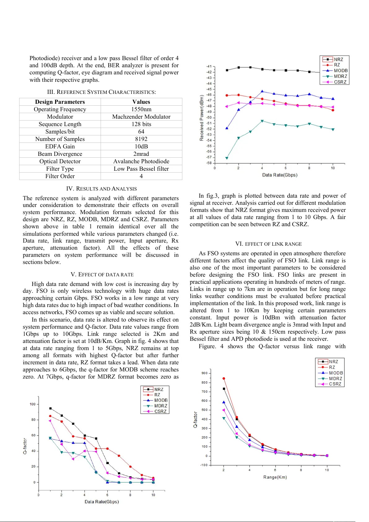
Parametric Investigation Of Different Modulation Techniques On Free Space Optical Systems Nauman Hameed b , Tayyab Mehm ood a, 1 , Anisa Qasim a, 2 a University Col lege of Eng ineering & Technolog y, the I slamia University B ahawalpur, Pak istan. b Department of Telecom municat ion Engineering , UET Taxila, Pakis tan. a, 1 tayyabjatoiba loch@gm ail.com , b nauman112te@gmail.com , a, 3 anisaqasim @gmail.com Abstract —Free Space Optics systems (FSO) is one of the evolving wireless technologies. FSO is the only technology with highest data rates in w ireless mode of operation but it suffers from bad w eather conditions. In this work, analysis is carried out on FSO syste m having cert ain parameters constant using different modulation formats (i .e. RZ, NRZ, MDRZ, M ODB and CSRZ). Impact of data rate, link range, input power and attenuation f actor has been computed. Weather conditions are supposed to be nearly clear and suitable for FSO communication while taking attenuation factor up to 10dB/Km. Q-factor, received signal power an d BER is calculated i n all scenarios for obtaining an estimate of system performance. Results have shown that NRZ & RZ formats are in the lead until now with highest Q values. Keywords — Free Space optics, Modulation formats, Q-factor, Received signal power. I. I NTRODUCTI ON Free Space Optics (FSO) also termed as Optical Wire less Technology is an e merging technology in which a lig ht is used as a medium for co mmunication. Although FSO is being used in satellite co mmunication yet its sig nificance can’t be denied in terrestria l mode of operation. FSO was first used for military p urposes due to its unmatc hed security, flexibilit y a nd ease of installation. Being ope rated at high carrier frequencies, FSO comes up with high data rates. Insensitivity to electro -magnetic interference a nd jamming, license free op eration, commercial availability, high level data protection, high bit rate s a nd lo w initial cost make FSO to be considered as a strong ca ndidate in next generation broadb and access networks [1]. FSO can be implemented where p hysical connectio n is not feasible. FSO has a very h igh impact of weather conditions (i.e. rai n, dust, fog, haze, snow). Before its imple mentation in so m e specific area or region, avera ge weather situation must be estimated. Differe nt phe nomenon affect light bea m in open atmosphere such as turbulence, absorption, scattering and scintillation. Bad weather conditions result in poor transmission and event ually lo w BER and signal po w er [2]. FSO links with 7km le ngth are in operation but it works best when distance is in hun dreds of meters [3]. The FS O link with shor t distance works well because attenuatio n in some w orst case s o f weather reaches 80-120 dB/Km. High transmitter power is needed to cope w ith such high de gree of attenuation. Optical a mplifiers are also used to mitigate the e ffect of attenuation. FSO can be a good choice for access networks which spa n hundreds of meters [4]. FSO is allowing e nd users to acce ss op tical connectivity reliably and at lo w per user cost. In wireless mode of op eration, FSO is the only technology with suc h high ba ndwidth. FSO has fascinating app lications in different sce narios such as last mile acce ss, co nnecting nearb y build ings, short ter m mobile lin ks, satellite co mmunication, disaste r recovery, temporary setup for events and m any more. FSO is also being used with RF & Mic rowave lin ks in hybrid [5]. Although having much advantages and innate qualities to be chosen a mong next generat ion networks, FSO still needs much improve ment to survive in bad weather conditio ns. So, one thing that matters is transmitter configuration a nd modulation techniques used. Different modulatio n for mats give dissimilar results and performance under different parameters. We have done a stud y and simulation based on certain par ameters using various modulation tec hniques (i.e. RZ , NRZ, MDRZ, MOD B, CSR Z). Experi ments have shown that external m odulation giv es better performance and BER as co mpared to direct modulation [ 6]. II. S I MULATION S ETUP The pro posed FSO system’s performance is studied based on different para m eters (i.e. Data rate, range, transmit power). Syst em simulatio n is performed in Optisystem and performance is a nalyzed usi ng BER analyzer. It gives us Q- factor, eye diagram analysis and received po wer of transmitted sig nal at receiver end. The reference system block diagra m is given in Fig. 1. Fig. 1 Block diagram of refe rence FSO sys tem In figure. 1, different blocks are shown. Each block gives the idea behind its function being per formed. First bloc k visualizes as PRBS (P seudo Random Bit Seq uence) generator wh ich creates data bits in binar y form a s 1’s and 0’s representing two differe nt states generally known as On & Off. P ulse generators for var ious modulation formats (i.e . NRZ, RZ, MODB, MDRZ a nd CSR Z) are symbolized by second block. T he o utput from thi s bloc k is fed into DML (Directly modulated laser) which is the par t of FSO transmitter a s shown i n third block. Cha nnel air inter face block between FSO transmitter and receiver is a medium of transmission. FSO receiver block contains AP D (Avala nche Photo diod e) receiver and a low pas s Bessel filter of ord er 4 and 100 dB dep th. At the end, BER analyzer i s pre sent for computing Q - factor, e y e diagr a m a nd rece ived sig nal po wer wi th t heir respe ctive grap hs. III . R EF ERENCE S YST EM C HA R A CTERI STICS : Design Pa ra m eters Values Oper ating Freq uency 15 50 nm Mod ulator Machzender Mod ulator Sequence Length 128 bits Sa m ples / bit 64 Num ber of Sa m ple s 81 92 EDFA Gain 10d B Beam Diver gence 2m rad Optical De tector Avalanche P hotodio de Filter T y pe Low Pa ss Bessel filter Filter Ord er 4 IV. R ESULT S AND A NALY SIS The refere nce syste m is anal yzed with di ff ere nt par a meter s un der consider ation to de m onstrate their effects on over all system per for m a nce. Mod ulation for m ats selected for this design are NRZ, RZ, MOD B, MDRZ a nd CSR Z. Pa ra m ete rs shown abo ve in table 1 re m ain ident ical o ver all the simulations per for m ed while various par a m eters c hanged (i .e. Data rate, link ra ng e, tra nsmit po w er, Inp ut aper ture, Rx aper ture, attenuation factor). All the e ff ec ts o f the se par am eter s on syste m per for m a nce wi ll be discussed in sections belo w. V. E FF ECT OF DATA RATE High data rate dem and w ith lo w cost is increas ing day by day. FSO is only w ireless t echnol ogy w ith hu ge data ra tes approach ing ce rtain Gbps . FS O w orks in a low range at ve ry hig h data rates due to hig h im p act of bad w eather c onditi ons. In access n etw orks, FSO comes u p as vi able an d secu re so lut i on. In this scena rio, data rate is alter ed to ob s erve its eff ect on sy stem per fo rm ance and Q - fa ctor . Data rate valu es range fr om 1Gbps u p to 10Gbps . Lin k range sele cted is 2Km and attenua ti on fac tor is set at 10d B/Km . Graph in fig. 4 show s that at data rate rang ing fr om 1 to 5Gbps , NRZ rem ains at t op am ong all fo rm ats w ith highest Q - fact or but afte r fu rth er incr em ent in data rate , RZ form at takes a lead. When data rate approach es t o 6Gbps, the q - fa ctor fo r MODB s chem e reach es zero. At 7Gbps, q - fact or fo r MDRZ form at bec om es z er o as can be seen in the fig . 2. At pe ak data rat e of 10Gbps, Q- factors are given as 3.57, 5.82, 0, 0 and 3.99 for NRZ, RZ, MODB, MDRZ and CSRZ res pectively . In fig .3 , gr aph is plott ed bet w een data rate and po w er of sign al at receive r. Ana ly sis car ried out fo r diffe rent m odulati on form ats show that NRZ form at gives m axim um received p ower at all v alues of data rate ran gin g from 1 t o 10 Gbps . A f air competi ti on can be se en betw e en RZ an d CSRZ. VI. EFF ECT OF LI NK RANG E As FSO sy stem s are oper ated in open atm ospher e the ref ore differ ent fact ors aff ect the qu ality of FSO link . Lin k range is also one of the m ost import ant param eters to be cons ide red befor e desig nin g the FSO link . FSO link s are pr esent in practic al applic ations operat ing in hu ndre ds of m eters of rang e. Lin ks in range up to 7km are in operati on but for l ong rang e link s w eather con ditions m ust be evalua ted befo re practi cal im plemen tation of the link . In this propose d w ork, link range is altere d fr om 1 to 10Km by keeping certa in param eters const ant. Input po w er is 10dBm w ith attenuati on fact or 2dB/Km . Ligh t beam divergen ce angle is 3m rad w ith Input and Rx apertur e si zes being 10 & 150cm respect ively . Low pass Bessel f i lter an d APD photo di ode is u se d a t th e re ceive r. F ig ure . 4 sh ow s the Q - factor v ersus link range w ith Fig. 2. Q-factor vs. D ata rate using di fferent modulation form ats. Fig. 3. Received Pow er vs. Data Rate us ing different modula tion for mats. Fig. 4. Q-factor vs. Ra nge using diffe rent modulation form ats. different modulation form ats. At link range up to 6Km, RZ form at rem ains at the top wi th hig hest Q - fact or am ong all form ats. Aft er that NRZ an d RZ y ields ne arly identi cal Q valu es u p t o 10 Km of link rang e. Besi des RZ and NR Z, MO DB f ormat is at thi rd posit ion . Q values are [21,11 ,6], [20, 10 ,5], [1 4,7, 4], [9 ,4, 2] and [14,8, 4] f or tran sm ission dist an ce 8 Km , 9Km and 10Km in case of NRZ , RZ , MODB , MD RZ and CSRZ respe ctivel y . Q - factor sh ow s tha t for l ong rang e link s NRZ is best ch oice but f or sm all ranges RZ perf o rm s well. Graph betw een receive d pow ers ve rs us l ink rang e is sh ow n in f ig . 5 . It sh ow s that NRZ resul ted in m axim um receive d sign al power wh ile MODB comes at second positi on . RZ in this case resu lts in a littl e bit lo w signal p ow ers as compare d to NR Z & MODB but i denti cal t o CSRZ form at. BER v alues ar e [1.1 94 e - 10 2 , 5.89e - 09 5 , 1. 524e - 0 48 , 2. 75e - 020 , 8.59 e - 0 48 ], [1 .41e - 30 , 6.01 1e - 28 , 6.71e - 015 , 8.74e - 07 , 2.18 e - 017 ] an d [8 .77e - 01 0 , 4.20e - 09 , 2.48 e - 05 , 6.14e - 03 , 1.97e - 06 ] f or tran sm ission distan ce 8 Km , 9Km and 10 Km in case of NRZ , RZ , MODB, MDRZ and CSR Z respectiv ely . VII. EFF ECT OF I NPUT PO W E R Tra ns mitter po wer is an impor tant factor which pla ys vital ro le in c o mm u nicatio n syste m . Althou gh we need to consu me le ss pow er but a little bit power penalt y ca n be good for reliab ility of t he link. I n this in stance, we have app lied various values of pow er at tra nsmitter fro m 3 dB m to 5dB m . Data rate, li nk rang e and atte nuatio n are 10G bps, 2Km and 10d B/Km resp ec tively . Fig ure . 6 clea rly show s the evaluated results in w hich NRZ form at is havin g hig hest Q val ues at all values of input power . Afte r tha t RZ is also perf orm ing w ell. But for MODB an d CSR Z , it can be s een tha t at v al ues of pow er from - 3 to 2d Bm CSRZ is out perform ing the MODB format and after further increase in pow er up to 5dBm MODB takes the lead . Perf orman ce of MDRZ is sa tisf acto ry in this case. Q - fact or values are [2 5, 30, 37], [2 4, 3 0, 36], [1 7, 21, 25], [1 1, 13, 16] and [1 6, 19, 22] fo r t ransm itte r pow er 3dBm , 4d Bm and 5dBm in cas e of NRZ, RZ , MODB , MDRZ and CSR Z r es pectivel y . Fig ure . 7 sh ow s the graph plo tted betw een receive d s ign al powers versus t ransm itter po w er. With inc rease in tran sm itter power, th ere is an inc rease i n receive d sign al pow er. In this event, NRZ rem ains at the fi rst posi ti on w ith peak rec eiv ed sign al pow er at all va lue s of In put po w er. MODB ’s perfo rm ance is bett er in th is ca se wh ile RZ & CSRZ are havin g ident ical values . Re ceiv ed pow er values are [ - 55, - 53 , - 51] , [ - 60, - 58, - 56 ], [ - 59, - 57 , - 55], [ - 64, - 62, - 60] an d [ - 60, - 58, - 56] for input pow er 3dBm , 4dBm and 5dBm in case of NRZ, RZ , MODB, MDRZ an d CSR Z r es pective ly . All valu es ar e in dBm . Fig. 5. Received Pow er vs. Range using differe nt modulation formats. Fig. 6. Q-factor vs. Tx Powe r using differe nt modulation formats. Fig. 7. Received Pow er vs. Tx Power using differe nt modulation formats. VIII . EFF ECT OF A TTEN UATIO N FACTOR Attenuat ion is one of the m ain fact or in any comm uni cation sy stem wh ich needs to be com pensated fo r relia ble qualit y comm uni cation. In FSO sy ste m , it is havin g a ve ry large eff ect acco rding to divers e w eather conditi on s . Operatin g fre quen cy is set at 1550nm due to its less exposu re t o atm ospher ic attenua ti on [6]. Input pow er is 10dBm & beam diverg ence in this case is 3m rad. EDF A w ith 10 dB gain is used . Transm ission of data rate is at 10Gbps & link range is 3Km. At recei ve r si de, APD photo - detect or is us ed w ith 3dB gai n, resp onsivit y 1 A/ W, i oni zatio n ratio 0.9 & da rk current 10 nA. Therm al noi se is als o consi dered . Six attenu ati on values (i.e . 1, 2, 3, 5, 7, 10dB/Km ) are t aken into acc ount fo r inv estiga ti on. As fig ure. 8 show s the eff ect of atten uati on on differ ent m od ulati on form ats versus Q - factor. It can be s een that RZ form at perfo rm s best un der all values of att enua ti on. At l ow values of att enuati on, the re i s a large dif fer ence in Q - fac tor values and i t rem ains m inor at larg e atten uat ion . The re is a close com petiti on betw een NRZ and RZ form at. At atten ua ti on value of 10dB/Km , Q - factor values fo r NRZ & RZ are 6.52 and 6.23 resp ectiv ely . Min . BER values fo r NRZ & RZ are 3.48× 10 - 11 an d 2.72× 10 - 10 res pectiv ely . Fig ure . 9 s how s the graph of receive d sign al power versus attenua ti on. In this case , NRZ out perf orms all oth er m od ulati on fo rm ats w ith hig hest sign al pow er at receive r s i de. RZ and CSRZ fo rm ats are h aving alm ost i dentic al receiv ed sign al pow er values . MDRZ schem e g ives lo w est receive d sign al p ow ers at al l va lues of a ttenuati on . IX. CONCL USION This w ork pres ents th e co m plete analy sis w ith cert ain param eters fix ed w hile some param eters being chang ed in differ e nt cases . For low data rates, NRZ is a best choi ce b ut f or hig her data rates f rom 6 t o 10 Gbps RZ rem ains at the top . F or short link ranges , RZ s eem s to be a g ood can did at e. It is conclu ded aft er obse rving vari ous eff ects on the propos ed sy stem that NRZ & RZ formats are suita ble fo r FSO sy ste m s acco rding to thei r perf orman ce. R EF ERENCES [1] Sana, H. Erkan, S. Ahme d, and M. A. Ali. "De sign a nd performance of h y brid FSO/RF a rchitecture for next generati on bro adband acc ess netw ork s." Proc. S PIE . Vol. 6390. 2 006. [2] Fadh il, Hilal A., et al. "Optim izatio n of fre e space op t ics parameters : An optim um so lution for bad w eat her cond itio ns." Optik - International Journal for Light and Electr on Optics 124.19 (2013): 3 969 - 3973. [3] Forin, Davide M., et al. "Free space op ti cal t echnologies." Trends in Telecommunica tio ns Techno logies (2010 ): 2 57 - 296. [4] Willebrand, Heinz, and Baks heesh S. Ghuman. Free spa ce op tics: enabling optical connecti vity in today's networks . Sa ms Publishing, 2002. [5] Kim, Isaac I., and Eric J. Korevaar. "Availability of free -space optics (FSO) and hybrid FSO/RF systems." ITCom 20 01: International Symposium on the Convergence of IT and Communications . International Society for Optics and Photonics, 2001. [6] Singh, Jitendra, and Naresh Kumar. "Performance anal ysis of different modulation format on free space optical communication system." Optik-International Journal for Light and Electron Optics 124.20 (2013): 4651-4654. Fig. 8. Q-factor vs. A ttenuatio n using different mo dulation formats. Fig. 9. Received Pow er vs. Tx Power using differe nt modulation formats. [7] Bloom, Scott, et al . "Understanding the performance of free - space opt ics [ Invited]." Journ al of optical Networking 2.6 (2003): 178-200.
Original Paper
Loading high-quality paper...
Comments & Academic Discussion
Loading comments...
Leave a Comment