Human Exposure to RF Fields in 5G Downlink
While cellular communications in millimeter wave (mmW) bands have been attracting significant research interest, their potential harmful impacts on human health are not as significantly studied. Prior research on human exposure to radio frequency (RF…
Authors: Imtiaz Nasim, Seungmo Kim
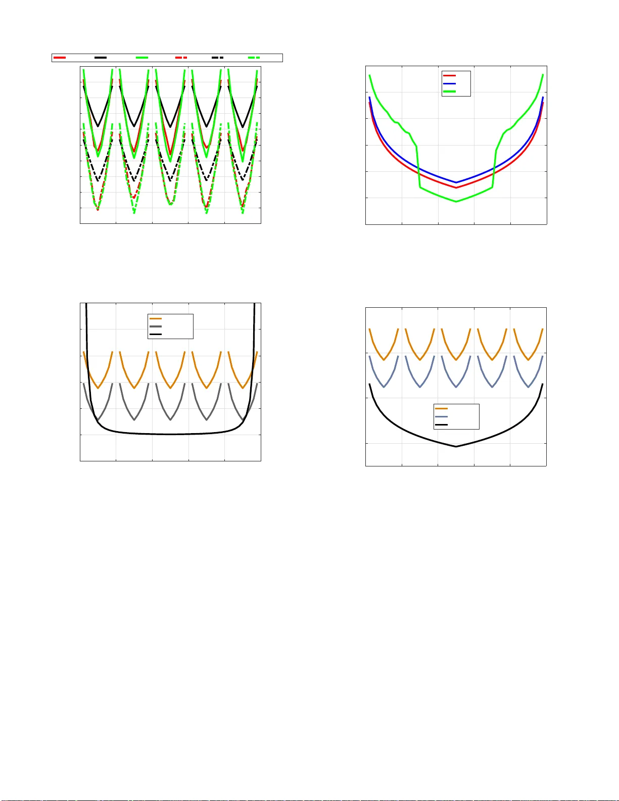
Human Exposu re to RF Fields in 5G Do wnlink Imtiaz Nasim and Seungmo Kim { in002 06, seungmo kim } @georgiasou thern.edu Departmen t of Electrical Engin eering, Geo rgia Southern Univ ersity Statesboro, GA 30460 , USA Abstract —While cellular communications in milli meter wav e (mmW) bands ha ve been attracting si gn i ficant re search inter est, their potential harmful impacts on human health a re not as significantly studied. Prior resear ch on human exposure to radio frequency (RF) fields in a cellular communications system has been focused on uplink only due to t h e closer physical contact of a transmitter t o a human b od y . Howev er , thi s paper claims the necessity of thorough in vestigation on human exposure to downlink RF fields, as cellu lar systems deployed in mmW bands will en t ail (i) dep loyment of more transmitters due to smaller cell size an d (ii) higher concentration of RF en ergy using a highly directional antenn a. In this paper , we present human RF exposure levels i n downlink of a F i fth Generation Wireless Systems (5G). Our results show that 5G d ownlink RF fields generate significantly higher p ower density (PD) and specific absorption rate (SAR) than a current cellular system. This paper also shows th at SAR should also be taken into account for determining hu man RF exposure in the mmW downlink. Index T erms —5G; mmW ; Downlink ; Human RF ex posure; PD; SAR. I . I N T R O D U C T I O N It is acknowledged that exposure to RF has negative impacts on human body . T h e rapid proliferation o f mobile telecom- munication s has occurred amid st con tr oversy o ver whether the technolo gy poses a risk to hum an health [1]. At mmW frequen cies where futu re mob ile telec o mmunica tions systems will likely op erate, two change s that will likely occu r have the potential to inc rease the concern o n exposure o f human users to RF fields. First, lar ger numb ers of transmitters will ope r ate. More b ase stations ( BSs) will be deployed d ue to pro liferation of small cells [2]-[4] and mobile devices a ccording ly . This will in crease ch ance of h uman expo su re to RF fields. Second, narr ower beams will be used as a solution fo r the high er attenuation in higher fr equency bands [3] -[7]. V ery small wa veleng ths of mmW signals combin ed with advances in RF circuits en able very large numbe rs o f m in iaturized anten n as. These mu ltiple antenn a systems can be used to for m very high gains. Such hig her con centration of RF energy will incr e ase the poten tial to more deeply penetra te into a huma n bod y . A. Related W ork This paper is motivated fr om th e fact that prior work is not enoug h to address such potential increase in threats. 1) Measur ement o f Human RF Expo sur e: Being aware o f the he alth haz a r ds du e to electromagn etic ( EM) em issions in mmW spectrum, inter national a gencies such as the Federal Communica tio ns Commission (FCC) [8] or the I nternation al Commission on Non-Ion izing Radiation Pro tection (ICNIRP) [9] set the m aximum radiation allowed to be introd uced in the human body without causing any health concer n. Po ssibilities of skin cancer du e to RF emissions at high er fr equency spec- trum are repo rted [10]. He ating due to EM expo sure in mmW is absor b ed within the first few millimeters (mm ) within the human skin ; fo r instance, the heat is ab sorbed within 0.41 mm for 4 2 .5 GHz [11]. The m mW ind uced burns ar e mo re likely to be conventional burns as like as a person touch ing a ho t object as repo rted in [1]. The nor m al tem perature for the skin ou ter surface is typically aro u nd 30 to 35 ◦ C. The pain detection threshold tempe r ature for human skin is app roximately 43 ◦ C as reported an d any temp e rature over that limit can produ ce long-ter m injuries. One problem is that the literature on the impa c t of cellular commun ications on hum an health is not mature eno ugh. The three major quantities used to me a su re the intensity and effects of RF expo sure are SAR, PD, an d the steady state or transien t temperatur e [12][13]. However , selection of an appropr iate metric ev aluating the human RF expo sure still rem ains co n- troversial. The FCC sug gests PD as a metric measu ring the human exposure to RF fields genera te d by devices op erating at f requencie s higher than 6 GH z [8], whereas a recen t study suggested that the PD standard is n ot efficient to determine the health issues e specially when devices are operating very close to human bod y in m mW [14]. T h erefore , this pape r examines the human RF exposure by using both PD an d SAR. 2) Reductio n of Huma n RF Exposure: V ery fe w prio r studies in the literatur e paid attention to human RF expo sure in commun ications systems [1][1 4]-[17]. Prop agation ch a r acter- istics at different mmW bands and th eir thermal effects were in vestigated f o r discussion on hea lth effects of RF expo sure in mmW radiation [14]. Emission reduction scheme and mo dels for SAR exposure constraints are studied in recent work [15][16]. Howe ver, health impacts o f mmW RF em issions in downlink of a cellular c ommun ic a tions system have not b een studied so far , which this paper targets to discuss. B. Contributions Three c o ntributions of this paper can be high lig hted and distinguished from the prior art. Firstly , this paper ana lyzes the hu man RF exposure in the downlink . All th e prior work studied an uplink o nly , while paid almost no atten tion to suppression o f RF fields generated by access points (APs) and BSs in a 5G no r Release 9 network, T ABLE I P A R A M E T E R S F O R 5 G A N D R E L E A S E 9 Parameter V alue 5G Release 9 Carrier frequency 28 GHz 1.9 GHz System layout RMa, UMa , UM i [18] SMa, UMa, UMi [21] Inter-site distance (ISD) 200 m 1,000 m Cell se c torization 3 sectors/site 6 sec tors/site Bandwidth 850 MHz 20 MHz Max a ntenna gain 5 dBi per element 17 dBi Transmit power 21 dBm per element 43 dBm AP’ s number of antennas ( λ/ 2 array) 8 × 8 and 16 × 16 4 × 4 AP antenna height 10 m 32 m Duplexing Time-d ivision duplexing (TDD) Transmission scheme Singler- user (SU)-MIMO UE noise figure 7 dB T emperature 290 K -500 -400 -300 -200 -100 0 100 200 300 400 500 position (m) -500 -400 -300 -200 -100 0 100 200 300 400 500 position (m) Fig. 1. A snapshot of one “drop” of 5G topology (19 s ites, 3 sectors per site, and 30 UEs per sector) respectively . In fact, APs g enerate ev en stro nger RF fields compare d to th e con current systems, due to (i) highe r transmit power and (ii) larger antenna a rray size leadin g to high er concentr a tion of RF e nergy . Moreover , one impo rtant feature of the fu ture cellular networks is small cell networks. The consequen ces of this chang e will be two-fold : (i) APs/BSs will serve smaller ge o graph ic areas an d thus are located closer to human users; (ii) larger numb ers of APs/BSs will be deployed , which will lead to higher chances of h uman exposure to the RF fields gener ated by downlinks. Secondly , this p aper finds th a t SAR sh o uld also b e con- sider ed in determ in ation of hum an RF exp osure in mm W downlinks. Our simu lations are perfo rmed for a 5G system based on the 3GPP Release 14 [ 18], one of the promisin g technical specifications for 5G. The results sho w that e ven considerin g a shallow p enetration into a hum a n body due to high frequ encies, a downlink RF emission causes significantly higher SAR in m mW . This effecti vely highlig h ts the elev atio n in po tential harm f ul impact in human health , which can ignite higher inte r est in further r esearch o n design of f uture cellular commun ications systems co nsidering th e impacts on human RF exposure. Thirdly , it explicitly comp ar es the h uman RF exposur e in downlinks between 5G an d Release 9 , high lighting the d iffer - ence in the size of a cell. This will lead to clear und erstanding on how the techn ical evolution to 5G affects the h uman RF exposure. This paper calculates PD a nd SAR of a 5 G [18] and a Release 9 [21] to highlight the change in huma n RF exposure a ccording to the technical e volution. I I . S Y S T E M M O D E L This section describe s the system setting for a ce llular commun ications network tha t form s the basis f or the analysis of human RF exposure . Considering the frequ ency spectru m of 28 GHz as a poten tial candidate for 5G, we use a corre- sponding technical repor t [18] that was re leased by the 3GPP . Also, this paper co mpares the human RF expo sure level in a 5G system to a legacy c e llular commun ications system. For highlighting how much a SAR lev el can b e increased compare d to the current wireless services, this pap er chose to compare the 5G to th e Release 9 [21]. The param eters of both systems are summarized in T able I. A. 5G 1) P ath Loss: Our model for a 5G system is ill ustrated in Fig. 1. It co nsists of 1 9 sites each h aving 3 sectors. The inter-site distance (I SD) is 2 0 0 meters (m) and each sector is assumed to have 3 0 active user equipments (UEs). A lso , as identified in T able I, fo r the ter r estrial pr o pagation betwee n an AP and a UE, th e following three path loss mod els are assumed: Rural Macro (RMa), Urban Macro (UMa), and Urban Micro (UMi) [18]. 2) Antenn a Beam P attern: For a 5G AP , the attenuation patterns of an antenn a element on the elev ation and azimuth plane are giv en by [1 8] A a ( φ ) = min ( 12 φ φ 3 db 2 , A m ) [dB] (1) A e ( θ ) = min ( 12 θ − 90 ◦ θ 3 db 2 , A m ) [dB] (2) where φ an d θ are angle s of a beam on the azimuth and elev ation plane, respe cti vely; ( · ) 3 db denotes an an gle at which a 3-dB loss occu rs. Then the an tenna element pattern that is combined in the two p lanes is given b y A ( θ, φ ) = min ( A a ( φ ) + A e ( θ ) , A m ) [dB] (3) where A m is a maximum attenua tio n (fro nt-to-ba ck ratio). I t is defined A m = 30 dB in [18], but it can be high er in practice. Finally , an an tenna g ain that is formulate d as G ( φ, θ ) = G max − A ( φ, θ ) [dB] (4) where G max is a maximum antenna gain. B. Release 9 1) P ath Loss: A cellu lar network opera tin g on Release 9 is designed to form a cell rad iu s of 500 m, which results in an ISD of 1, 000 m. T his p aper calcu la te s the received power in a d ownlink, fo llowing the path loss models pr ovid ed in [21]– Suburban Macr o (SMa) , UMa, a n d UMi. 2) Antenn a Beam P attern: The antenna radiatio n pattern for a Release 9 BS is also gi ven as (1) and (2 ). Howe ver , unlike at a 5G AP , θ 3 db and A m for a Release 9 BS are given as 35 ◦ and 23 dB, respectively . I I I . P E R F O R M A N C E A NA L Y S I S In this section, we p resent an analysis on the hum an RF exposure in a 5G com munication s a nd a Release 9 s ystem. Thoug h we chose 28 GHz frequ ency spectrum for 5G perfo r- mance analysis, performan ce f or any other frequen cy spectrum can be demonstrated follo win g the same methodo logy . It is obvious that the high er number of elements u sed in the antenna give better sign a l power , the outcom e also in creases the cost an d comp lication of the antenna design . The present technolog y has a large cell size wh ere a single BS can pr ovide coverage to more than tho u sands o f meters, but the cell size of 5G is r e lati vely small. In a mo del like Release 9, there may be on e BS u sed to provide coverage to a wid e a rea for providing service to UEs, but in 5 G scenar io, the same area is covered by a nu mber of scattered APs to provide a better reliable service. A. Data Rate The downlink p e r forman ce of a system is calcu la te d f rom the Shanno n’ s form ula, which is given by R = B log(1 + SNR) (5) where R and B denotes a data rate an d ba n dwidth, respec- ti vely . Signal-to-n oise p ower ratio (SNR) is u sed to determ in e a d ata r ate. Note that the inter-cell interf erence is not consid- ered for simp licity in calcu lation as the fo cus o f this paper is analysis of hum an exposure lev el, which is n ot influenced by th e interf erence. In this paper, we calculate a SNR for the UEs con sidering all the po ssible locations in a sector tha t is formed by an AP in a 5 G system and a BS in a Release 9 system. Howe ver, an acc urate thr ee-dimension al distan ce is considered with the exact heig h ts of an A P , BS, and UE which are taken into acco unt referred from [18]. In other words, although the ho rizontal axes of the re sults provided in Section IV present all the po ssible location s in a cellu lar system, th ey in fact demon strate three- d imensional distanc e s with the exact vertical d istances ac c ounted. The co re part in calcu lation of a SNR is a received p ower that is direc tly determ in ed by a pa th loss model provid ed in the specification s [1 8][21]. Here we provide an analysis framework for th e signal p ower that is received by a UE from eith e r an AP or a BS in a sin g le downlink, deno ted by P R,ue . It is noteworthy that with straightfor ward modifications, this framework can easily be extend ed to an uplink received signal power also. A receiv ed sig n al streng th in a downlink transmission of a sing le sector is com puted by averaging over all po ssible downlink directio ns accord in g to p o sition of the UE, which is given b y P R,ue ( x ue ) = 1 |R 2 k | Z x ( k ) ue ∈R 2 k P T ,ap G ap ( x ue ) G ue ( x ue ) P L ap → ue d x ue (6) where R 2 k is region o f a sector and thu s R 2 k is the area of a sector; x ue is position of a UE in an R 2 k ; P T ,ap is transmit power o f an AP; G ap and G ue are the antenn a beamfor ming gains of an AP and a UE, respectively , in a downlink transmission based on (4); P L ap → ss is the path loss between the AP and the UE. B. Human RF Exposure T o d etermine the deleterious impac ts of RF emission s to th e human bo d y in mmW spectrum , SAR and PD are the m ost common ly used e valuation criteria so far . As th ere remains a controversy which method is mo re accu r ate one to be considered , whether it is a far-field or near-field case, we show both the analysis for SAR and PD for futur e techno logy . The SAR is a quantitative measure that represents the power dissipated pe r bo dy m ass. It is one of the Intern a tional System of Units (SI), wh ich is mea su red in watts (W) per kilogram (kg) and is given by SAR = P diss m = σ | E | 2 ρ (7) where P diss represents dissipated power in tissue in the unit of W , m represents the exposed tissue mass in th e unit of k g, ρ is th e tissue mass d ensity (kg/m 3 ), σ is the co nductivity in siemens per meter (S/m) an d E is a root mean square (rms) value of the electric-field strength which is g iv en in the unit of voltage per meter (V/m ). T he SAR for a particu lar tissue in human body is d ifferent from the SAR for a tissue at different location. Also, SAR at the sur face of the exposed tissue is different fro m the SAR deep within that exposed tissue. The PD o f a transmitting antenna f or the far-field can be expressed as [1] PD = | E i | 2 η = η | H i | 2 (8) where E i (V/m) and H i (A/m) are rms values of the electric and magnetic field streng ths, r espectively , inc ident on the tissue surface and η is the w ave impedance in the unit of ohm ( Ω ). The SI u nit of a PD is W/m 2 , which ind icates that a PD is a measuremen t of the power d issipated per area of the exposed tissue. Our paper fo cuses on the downlink behaviors when perform - ing the analysis and c o mparison of the two comm unications system. Incid e nt PD for far -field commun ications is expressed as S i = P T G T 4 π d 2 (9) 0 200 400 600 800 1000 Location (m) -30 -25 -20 -15 -10 -5 0 5 10 Received Power (dB) UMa (16x16) RMa (16x16) UMi (16x16) UMa (8x8) RMa (8x8) UMi (8x8) Fig. 2. Recei ved signal power (6) versus UE locat ion in a 5G system (APs are located at 0, 200, 400, 600, 800, and 1,000 m) 0 200 400 600 800 1000 Location (m) -80 -70 -60 -50 -40 -30 -20 -10 0 Received Power (dB) SMa UMa UMi Fig. 3. Recei ved signal powe r (6) versus UE location in a Relea s e 9 system (BSs are located at 0 and 1,000 m) where P T is a tra n smit power; G T is a tra n smit anten na g ain; d is the AP-UE distance (m) as in (6). Now , we can rewrite an SAR g iv en in (7) in terms of d fo r calculation in a cellular co mmunicatio ns system, which is also a function of φ [19][17], as SAR ( d ) = SAR ( φ ) = 2 S i ( φ ) T ( φ ) m ( φ ) δ ρ (10) where T is the power tr a n smission co efficient [16] and δ is the skin pe n etration depth (m) at 2 8 GHz [14]. The fu nction m ( φ ) [16] is d ependen t o n the tissue prop e rties of dielectric constant ( ǫ ∗ ). In ord er to accu rately study a m mW signal pro pagation and absorption in a hum an bo dy , investigation on the p arameters related to dielectr ic m easurements on human skin are ne c e s- sary . Specifically the values of the p arameters, ρ , ǫ ∗ , δ , T , and m ( φ ) are obtained from prior related work [13][14][18][20]. I V . E V A L U A T I O N O F H U M A N R F E X P O S U R E In this sectio n, we analyz e the results for the pe rforman ce o f 5G technolog y and make a compreh ensiv e com parison of the model with p resent Release 9. First we show the perfo rmance for 5G in terms of service quality and then make a dee p er interest in the health impacts due to exposure to EM em ission s at mmW radiation . A. Data Rate W e co n sider two an tenna a rray sizes: 8 × 8 an d 16 × 16 for 5G ana lysis. As we co nsider 3 sectors und er each AP , it is adeq uate for each antenna to have the coverage of 120 ◦ capability to cover an entire 360 ◦ range of the cell. Figs. 2 and 3 show the signal power received at a UE, P R,ue ( x ue ) , at different location s in 5 G an d Release 9 scenar- ios, resp ectiv ely . The most significan t factor that determ ines a received signal p ower is path loss that is in turn d ominated by the L oS probability provided differently in each path loss model [18]. The rec ei ved power decreases shar p ly with increasing distanc e in bo th systems, but a s the APs ar e located at muc h closer p o sitions for 5G , the receiv e d p ower b ounces back to increase ag a in while it keeps on decreasing with increasing distance in a Release 9 sy stem. Also, it can be seen from Fig s. 2 an d 3 that ev e n at the cell edges ( at 100, 300, 500, 700 , and 90 0 m), the r eceiv ed power is still rem arkably higher fo r all 5G scenarios than the respective scenarios of the Release 9. On e key ratio nale behind this outp e r forman ce can obviously be found as the higher antenna g ain that an AP can form by adopting the larger p hased ar rays. Figs. 4 and 5 show data r ates that can b e achieved in a 5 G and a Release 9 system, respectively , to re present the downlink perfor mances. One can obviously find that a higher received power dir ectly leads to a higher d a ta rate (as observed fro m compariso n to Figs. 2 and 3 ), consider ing the data rate th at is calculated from (5). Fig. 4 illustrates a comparison of data rates achieved in a 5G downlink system b etween different AP’ s phased array size–16 × 16 and 8 × 8. It can b e seen that a UE in all 5G scenarios yields a downlink d ata rate above 13 Gbps e ven at a cell edg e. Fig. 5 pr esents d ownlink d ata r ates in a Release 9 system. It shou ld be emphasized fro m Figs. 4 and 5 that in spite of the disadvantage in the propagatio n due to the hig her carrier freq uency , a 5G system pr esents appr o ximately 20- times high er downlink r a tes comp a red to a Release 9 system regardless of (i) the p ath loss mod e l and (ii) an AP’ s phased array size. The main rationale behind such a significant outperf ormance is the smaller ISD in a 5G sy stem. It is thu s evident th at the 5G m mW techn ology provid es significan tly better pe rforman ce to the consumer as it provides better sig nal strength with h igher d ata transmission cap a bilities at the user end. 0 200 400 600 800 1000 Location (m) 13 14 15 16 17 18 19 20 21 22 23 Data Rate (Gbps) UMa (16x16) RMa (16x16) UMi (16x16) UMa (8x8) RMa (8x8) UMi (8x8) Fig. 4. Data rate (5) ve rsus UE locati on in a 5G system (APs are locat ed at 0, 200, 400, 600, 800, and 1, 000 m) 0 200 400 600 800 1000 Location (m) 0 0.1 0.2 0.3 0.4 0.5 0.6 Data Rate (Gbps) UMa SMa UMi Fig. 5. Data rate (5) versus UE location in a Release 9 system (BSs are locate d at 0 and 1,000 m) 0 200 400 600 800 1000 Location (m) -10 0 10 20 30 40 50 Power Density (W/m 2 ) 5G (16x16) 5G (8x8) Release 9 Fig. 6. Power density (8) versus UE locatio n in a 5G and Release 9 system 0 200 400 600 800 1000 Location (m) 10 -2 10 0 10 2 10 4 SAR (W/kg) 5G (16x16) 5G (8x8) Release 9 Fig. 7. SAR (7) versus UE location in a 5G and Rele ase 9 system B. Human RF Exposure Now we show that ev en co n sidering such shallow penetra- tion dep th due to h ig h frequen cies, a downlink RF emission causes significantly higher SAR in mmW . In this section , th e PD and SAR ar e compared be twe e n a 5G and a Release 9 system. It still remains not con c lu ded in the liter a ture wh ich of PD and SAR is more appro priate to rep resent the hum a n RF exposure level in far-field RF prop agations. W e claim that SAR should n ot be excluded in measurement of human RF exposure in mm W downlinks. The ra tio nale is that in spite of shallower pen etration into a human body co mpared to lower frequen cies, a mmW RF field causes a higher SAR due to (i) smaller cell radius and (ii) h ig her conce ntration o f RF energy per beam via adop tion of larger phased array . Fig. 6 c ompares the PD b etween the downlinks of 5G and Release 9. On e can find far highe r PDs in 5 G downlinks compare d to those of a Release 9 system. The same ration ale yields this hig her PD in 5G downlinks: the PD in a 5G system bounc e s back up at a shor ter distance compa r ed to a Release 9 system due to th e smaller ISD. In other words, the denser deployment of c ell sites in 5G keeps PDs h igher in more ar e as in a network tha n in a Release 9 network. At a distance ab out 50 m fr om the n e arest AP for 5G, the user is expo sed to a significant PD v a lu e when a 16 × 16 array is used. Th u s, when a larger ph ased an te n na is u sed or when a user moves closer to the AP , the PD value beco mes a ma jo r health concern which inevitably requir es more research about health effects of 5G befor e it is deployed su ccessfully by strictly following the RF emission standards. W e show the comparison of SAR also between 5G an d present existing scen ario in Fig. 7 for far-field to have a be tter understan ding a b out the health impacts of RF emissions into human body . The SAR r equiremen ts for near-field is stated in [1], but to the best of ou r k nowledge, ther e is no stand ard provided for SAR in far-field scenario so far as it is expected that SAR does n ot have a significant effect on hu man body in far - field. Ou r result in Fig. 7 presents th at a 5G downlink does not allow a sufficient far-field pr opagation du e to the small-cell topolog y . This yields a much higher SAR level than Release 9 that adop ts a larger ISD th at consequ ently yields a longer p ropag a tio n th at is sufficient fall down to a low enoug h SAR. This is resulted f rom the mmW radiations, antenna beam steerin g effects and sm a r t antenna character istics of 5G architectu r e. The result provided in Fig. 7 has a significant imp lication. According to the I CNIRP guide lin es [9], th e maximu m allow- able SAR level for head an d tru nk is 2 W/kg and f o r lim b s it is 4 W/kg for 10 g tissue over 6 minutes of exposure for frequen cies up to 10 GHz for gen eral public (ICNIRP and FCC [8] do no t have SAR guidelin es fo r mmW like 28 GHz far -field scen ario yet, as it is expected to be less danger ous). But our result p r esented in Fig. 7 shows a significan t incr e ase in SAR in 5G d ownlinks compa r ed to th e Release 9, even in such far-field pr opagation s. Considerin g the significance of a regulatory guideline in the societal endeav o r to p rev ent injuries from over-exposure, th is pap er hereb y strong ly urges that it is not safe enough with the PD so lely being c o nsidered as a basic restriction in hu m an RF expo su re in mmW o perations. Our result sug gests that the SAR should also be con sidered as a m e asuring para m eter even f or far -field, pa rticularly in mmW commun ications d ue to its rec e ived signal strength remaining strong at an end user . V . C O N C L U S I O N S This paper h as highlighted the significan ce of hum an RF exposure issue in d ownlink of a cellular communication s system. This paper me asured the expo sure level in terms o f PD and SAR, an d compared the m to tho se calculated in the Release 9 as a representative of the cur rent mobile commun ica- tions technolo gy . Distingu ished from the prior art that studied uplinks on ly , this p aper has fou nd that the downlinks of a 5G also yield significantly higher levels of PD an d SAR compar ed to a Release 9 . Our results em phasized that the in crease stems from two technical ch anges that will likely occur in 5G: ( i) more APs due to deploymen t of smaller cells and (ii) m ore highly co ncentrated RF energy per d ownlink RF b eam due to use of larger ph ased arrays. As such, unlike the prior work, this pap er claims that RF fields g enerated in d ownlinks o f 5G can also be dan gerous in spite of far -field p ropaga tio ns. Therefo re, we here urge design of cellular commun ications and n etworking sch emes tha t force an AP to av o id gen eration of RF fields if pointed at a huma n user with an angle yielding a dangero us le vel of PD and SAR. T o th is end, this paper id entifies as the fu tu re work p roposition of tec hniques that reduces hu man exposure to RF fields in 5 G downlinks. R E F E R E N C E S [1] T . W u, T . Rappaport, and C. Colli ns, “Safe for genera tions to come: Considera tions of safety for millimeter wav es in wirel ess communica- tions, ” IEEE Micr owave , vol. 16, no. 2, pp. 65- 84, 2015. [2] O. Al-Saadeh, and K. Sung, “ A performanc e comparison of in-band full duple x and dynamic TDD for 5G indoor wireless netw orks, ” EURA SIP J ournal on W ireless Communications and Networki ng , 2017. [3] T . Rappaport , S . Sun, R. Mayzu s, H. Z hao, Y . Azar , K. W ang, G. W ong, J. Schulz, M. Samimi, and F . Gutierrez, “Millimet er wave mobile communicat ions for 5G cellu lar: It will work!” IEE E Access , vol. 1, no. 1, pp. 335-349, 2013. [4] M. Agiwal, A. Roy , and N. Saxe na, “Next Generation 5G W ireless Networ ks: A Comprehensi ve Surve y , ” IEE E Communica tions Surve ys & Tu torials , vol. 18, no. 3, pp. 1617-1655, Feb . 2016. [5] J. Zhang, X. Ge, Q. Li, M. Guiza ni, and Y . Zhang, “5G millimeter -wav e antenna array: design and challe nges, ” IEEE W irel ess Communications , Apr . 2017. [6] S. Shakib, H. Park, J. Dunworth, V . Aparin, and K. Entesari, “ A highly ef ficient and linear power amplifie r for 28-GHz 5G phased array radios in 28-nm CMOS, ” IEE E J . Solid-State Circ uits , vol. 51, no. 12, Dec. 2016. [7] M. Akdeniz, Y . Liu, M. Samimi, S. Sun, S. Rangan, T . Rappaport, and E. Erkip, “Millimeter wa ve channel modeling and cellula r capacity e valuat ion, ” IEEE J. Sel. Areas Commun. , vol . 32, no. 6, Jun. 2014. [8] Eva luatin g Compliance with FCC Guidel ines for Human Exposure to Radiofreq uenc y Electromagnet ic Fields, W ashington, D.C.: Federal Communicat ions Commission, T ech. Rep. Suppl. C to OET Bulletin 65, 2001. [9] Internat ional Commission on Non-Ioniz ing Radiation Protection, “IC- NIRP guidel ines: for limiting exposur e to time-v arying electri c, mag- netic and electromagn etic fields (up to 300 GH z), ” Health Physics , vol. 74, no. 4, pp. 494-522, 1998. [10] United States Gov ernment Accountabi lity Office , “T elecommunic ations: expo sure and testing req uirements for mobile phones should be re- assessed, ” GA O-12-771 , Aug. 2012. [11] S. Aleksee v and M. Ziskin, “Mil limeter wav e power density in aqueous biologi cal samples, ” Bioelec troma gnetics , vol. 22, no. 4, pp. 288-291, May 2001. [12] IEEE standard for safet y le vels with r espect to human e xposur e to the radio frequenc y electr omagne tic fiel ds, 3 kHz to 300 GHz , IEEE Standard C95.1, 1992. [13] IEEE standard for safet y le vels with r espect to human e xposur e to the radio frequenc y electr omagne tic fiel ds, 3 kHz to 300 GHz , IEEE Standard C95.1, 2005. [14] T . Wu, T . Rappaport, and C. Colli ns, “The human body and millimeter - wa ve wireless communica tion systems: interactio ns and implications, ” in Proc . IEEE Internation al Confere nce on Communic ations (ICC) , pp. 2423-2429, 2015. [15] Y . A . Sambo, F . Heliot, and M. Imran, “Electromagne tic emission- aw are scheduli ng for the uplink of coordina ted OFDM wirele ss sys- tems, ” in Proc. IEEE Online Confer ence on Green Communicat ions (OnlineGr eenComm) , pp. 42-46, 2015. [16] M. Castellanos, D. L ove, and B. Hochwal d, “Hybrid precoding for millimet er wa ve systems w ith a co nstraint on user elec tromagnetic radiat ion expo sure, ” in Proc. Asilomar Conferen ce on Signals, Systems and Computers , Nov . 2016. [17] N. Chahat, M. Z hadobov , L. Le Coq, S. Alekseev , and R. Saulea u, “Chara cteriz ation of the inte ractio ns between a 60-GHz ante nna and the human body in an off-body scenario, ” IEEE T rans. A ntennas Prop . , vol. 60, no. 12, pp. 5958-5965, 2012. [18] 3r d gene ration partnership pr oject; tech nical specific ation gr oup radio access network; channe l model for frequ ency spectrum above 6 GHz (Release 14) , 3GPP TR 38.900 v1.0.0, Jun. 2016. [19] O. Gandhi and A. Riazi , “ Absorpti on of millimeter wav es by human beings and its biological implicat ions, ” IEEE T rans. Micr ow . Theory T ech. , vol. 34, no. 2, pp. 228-235, 1986. [20] P . Hasgall, E. Neufeld, M. Gosselin, A. Klingenbc k, and N. Kuster , “ITIS databa se for therma l and electro magnetic paramete rs of biologica l tissues, ” ver . 2. 5, Aug. 2014. [21] 3r d gene ration partnership pr oject; tech nical specific ation gr oup radio access network; spatial channel model for multiple input multi output (MIMO) simulations (Release 9) , 3GPP T R 25.996, v9.0.0 Dec. 2009.
Original Paper
Loading high-quality paper...
Comments & Academic Discussion
Loading comments...
Leave a Comment