Windowed Overlapped frequency-domain Block Filtering Approach for Direct Sequence Signal Acquisition
This paper applies a windowed frequency-domain overlapped block filtering approach for the acquisition of direct sequence signals. The windows, as a novel viewpoint, not only allow pulse shaping without a front end pulse shaping filter, but also impr…
Authors: Ebrahim Karami, Harri Saarnisaari
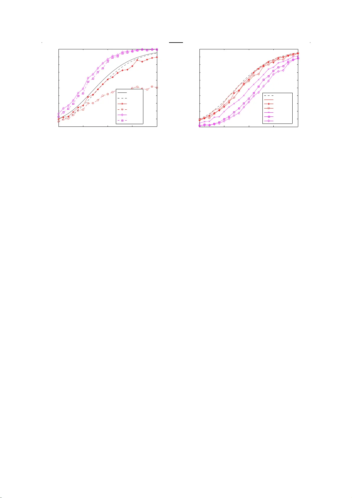
Digital Communications and Net works(DCN) journal homepage: www .elsevier .com/locate/dcan Win dow ed Ov e r lapped frequency -domain Bl ock F il tering Approach for Direct Sequence Signal Acquisi tion Ebrahim Karami ∗ a , Harri Saar nisaari b a Department of Eng ineering and Applied Sciences, Memorial Uni versity , Canada, b Centre for Wireless Communicatio ns, University of Oulu, Finland Abstract This paper ap plies a windowe d frequency-domain ov erlapped block filtering approach for the acqu isition of direct sequence signals. The windows, as a nov el viewpoint, not only allow pu lse shaping without a front end p ulse shap- ing filter , b u t also improve the performance of the spectrum sensing uni t which can e ffi ciently be implemented into this frequency -domain receiv er and ma y further be used for spectrum sensing in cognitive radios or narrow band interfer ence cancellation in military radios. The pro posed rece iver i s a p plicable for initial tim e synch ronization of di ff erent signal s containing a preamble. These si gnals include si ng le carrier , const ant -e nv elope single-carrier , multi-carrier and ev en generalized-multi-carr ier signal s , which makes the proposed rece iver structure a univer sal unit. Furthe rmore, the receiver can b e used to perfo rm fi ltering with long codes and compute th e sliding corr e- lation of an unknown periodic preamble. It can further be modified to handle large Doppler shifts. W e will also demonstra te the computational complexity and analysis of the acquisition performance in Rayle igh and Rician fading channels. KEYW OR DS: Synchronization, pseudonoise coded communication, matched filters. 1. Introd uction Initial synchronization, or acquisition of a di- rect sequence (DS) signal appears to be a quite common first step that a communication receiver has to p erform af ter switching the power on, be- cause man y wireless standards either use a DS signaling or th eir pr eamble, used for synchro- nization purposes, is a DS signal. These stan- dards include GSM, L TE, UMTS, GPS, G ALILEO, WIMAX, Zigbee, and man y others wireless stan- dards [1–4]. For example, L TE systems use two DS signals, i.e., a 62-length Zado ff -Chu sequence and an 31-length M-sequence, as primary and secondary synchronization signals [5]. On the ∗ Ebrahim karami is responsib le for all correspond ance (email:ekarami@m un.ca). other hand, the performance of channel est ima- tion and equalization, and data detection, alg o- rithms is significantly a ff ected by the accuracy of the initial synchronization [6–13]. One so- luti on to improve the synchron ization robust - ness is to use interfe rence cancellation (IC) sig- nal p rocessing [14–17]. Notch filters are well - known examples of these. Another ap plication for these IC units is spectrum sensing in cog- nitive radios. A notch filter may be a sepa- rate stand-al one unit in the fr ont of a conven- tional receiver , but they may also be integra ted into a frequency- domain receiv er , which red uces the co mplexity , beca use the required transfor - mations may be shared. frequency-d omain re- ceive rs require less complexity a n d hence, have found m a ny applications. One par ticularly inter - 2 Ebrahim Karami, et al. esting typ e of filtering is matched fi ltering, which allows fast acquisition [18, 19 ]. In tra ditional frequency-d omain filtering, where the filter is in a one piece, overlap-s av e (OLS) or overlap- add (OLA) methods have to be acquired to prop- erl y handle the conv olu tion process [20]. More- over , the frequency-domain receivers may be of interest in multipurpose or universal receivers, becaus e they can be naturall y used not only to receive m ulti-carrier signals such as orthogo- nal frequency division multiplexing (OFD M) and its v ariants as MC-CDMA [21] and generalized- mul ti-carrier (GMC) [22] signals but also to re- ceive single-carrier signals [23]. Some systems employ long DS codes an d con- sequentl y require long filters which are di ffi cult to implement [24, 25]. In such cases, the fil- tering has to be divided into blocks and the re- quired fil tering process has to b e performed us- ing a pr o cess known as a block or partitioned filtering [26 ]. This technique is well-known in audio signal pro cessing [27, 28]. Eve n overlap- ping blocks m ay be used [28, 29]. Block filters may also be adapted to acquire larger Doppler shifts than sole fi lters, see [30–33] for time- domain app roach. Block filtering is equal to DFT filter banks (mul ti-rate filters) and linear periodic time varying (LPTV) fi ltering [26] but also s hort time Fourier transform (STFT)-based- filtering [34]. The STFT adds windows, not used in DFT filter banks or LPTV filte rs, to the overall picture. The windows may be used to perform the puls e shape fil tering, i.e., to match the filter frequency response to that o f the signal and to improve the p erformance of notch filters by re- ducing the spe ctral leakage . Howev er , although essential for p r oper performanc e of notch filters, windowing is known to caus e signal-to-noise ra- tio (SNR) losses which are up to 3 dB for g ood windows. T his loss may be reduced almost down to zero dB using overlapping segments, which are also elementary for STFT -based-processing [35]. A STFT -based-correlator DS-receiver is pre- sented in [36]. In addition to data demodula- tion inv estigat ed in [36 ], it may be used for se- rial search acquisition, w hich is known to result a slow er acquisiti on than the match ed filtering ac- quisition inv estigat ed herein. This paper pr esents a frequency-domain, win- dowed, over lapped block fi ltering approach for DS signal acquisition. In addition to introduc- ing the filtering and the acquisition concept, its other possible applications in ra dio com munica- tions will be briefly discussed. These include i) addition o f a particular notch fil ter m ethod [37] into the receive r chain, ii) processing of di ff er - ent signals like conventional DS, co nstant en- vel ope DS, OFD M (WIMAX), MC-CDMA and GMC, iii) adaption the r eceiver to handle large Doppler frequency uncertainties and iv) possi- ble changes when receiv er is turned to the de- modula tion phase after acquisition. Furth er - more, the paper includes analysi s of computa- tional complexity of the receiver co mpared to the co nventional (non-block) matched filter im- plementation in the time or frequency-domain as well as analysis of acq uisition probabilities in additive white Gaussian noise (A W GN) and Rayleigh flat fading channels, of which the latter are novel resu lts. The probabili ties incl ude con- venti onal detection and false alarm pro babilities , maximum-se arch-based-probabiliti es and max- imum search followed by threshold-det ection- based-probabilit ies o ff ering a very comprehen- sive picture of receiver’ s performance. These probabilities may be used to set the detection threshol d and to predict the receiv ers perfor - mance in practice. As a summary of this it could be said that the paper intro duces a flexi- ble baseband ar chitecture tha t ma y be us ed with most existing and future signals and which of - fers spectrum sensing or narro w band interfer - ence rejection capability with a low additional cost. Therefore, the prop osed receiv er structure is a candida te receiver architecture for future mul ti-w av eform platforms. The rest of the paper is organized as fol- lows. Section 2 introduces the filtering concept whereas app lications and modifications are dis- cussed in section 3. The ac quisition process is analyzed in section 4 an d simulation results con- firming the analysis are shown in section 5. Fi- nally , con c lusions will be drawn in section 6. 2. Blo ck Filtering This section first discusses block -wise conv o- luti on to provide an insight how the block fil- tering works and then present its mathema tical frequency-d omain basis, the S TFT -based time- v arying filtering. 2.1. An Example A simple example is probabl y the bes t wa y to explain how the block filtering di ff ers from the conve ntional one. Let x 1 , x 2 , x 3 , x 4 be the sig- nal block to be filtered. In the conventional fil- tering, the signal is continuousl y fed into the filter whose im pulse response is h 1 , h 2 , h 3 , h 4 . As a consequence, the response sequence is x 1 h 1 , x 1 h 2 + x 2 h 1 , x 1 h 3 + x 2 h 2 + x 3 h 1 , x 1 h 4 + x 2 h 3 + x 3 h 2 + x 4 h 1 (desired phase in acquisition) , x 2 h 4 + x 3 h 3 + x 4 h 2 , x 3 h 4 + x 4 h 3 , x 4 h 4 . T he block -wise con- vol ution should end up to the same result. In the b lock processing, the signal and the fil- ter are divided into blocks using equal divisions. Windowed O verlapped frequency-domain Block Fil tering App roach for Direct S equence Signal Acquisition 3 In the example, the division of the signal could be (the fi lter is divide d correspondingly) " x 3 x 1 x 4 x 2 # , where the block size M = 2 and totality is 2 × 2 matrix. In the abse nce of noise, the signal stream include s zero bl ocks in both sides. In other words, the signal matrix stream is 0 x 3 x 1 0 0 x 4 x 2 0 . This is divi ded into 2 × 2 matrices by d iscarding the oldest data and taking a new block in. The input matrices, the first on right , are therefore " x 1 0 x 2 0 # " x 3 x 1 x 4 x 2 # " 0 x 3 0 x 4 # . In the block processing, only one input matrix is processed at each time ins tant , called as a filter - ing cycle. Each block (column) of an input ma- trix is convolv ed with the corresponding block (column) of a filter and the results are added togethe r . Then, the next input matrix in the next cycle is receiv ed and th e operations are re- peated. Theref ore, M responses ar e calculate d in one time cycle. T o obtain the whole response, the operation has to be repeated for all L possi- ble cycles. S ince the length of block convolu tion is 2 M − 1, the tails hav e to be added to the corre- sponding conv olu tions in the next cycle. This is clarified next. It is assumed that each block (col- umn) of the signal (matrix) passes a filter block from down to top. The co r responding convol u- tion results are added together from each filter - ing cyc le. The cycles are separated by bars and tails are below the dot lines. This result s x 1 h 1 | x 1 h 3 + x 3 h 1 | x 3 h 3 x 1 h 2 + x 2 h 1 | x 1 h 4 + x 2 h 3 | x 3 h 4 + x 4 h 3 | + x 3 h 2 + x 4 h 1 | . . . | . . . | . . . x 2 h 2 | x 2 h 4 + x 4 h 2 | x 4 h 4 . The t ails of t he conv olut ion ha ve to be added to the head of the convol ution in the next cycle. More precisely , let c k = [ h h t k ] denote the con- vol ution result in cycle k , where h k is the head (first M samples) and t k the tail. In the next cycle c k +1 = [ h k +1 + t k t k +1 ]. Therefore, the re- sponse of the block convol ution becomes equiv a- lent to the conve ntional co nv olution. As a s um- mary: the signal stream is block by block fed through the filter , the c o lumn- wise convoluti on betwe en the signal and the filter is p erformed, the c onvol ution result s are added colu mn-wise togethe r and the tails have to be added to the head o f the next cycle. Since the convolu tion in the time-domain might be equally well per - formed in the frequency-domain, in each cycle the FFT of the signal (matrix) can be element - wise mul tiplied by the FFT of the filter (matrix) and then is inv erse transformed to obtain the time-domain convol ution. After tha t, the co nvo- luti on resul ts are added together and OLA pro- cessing is performed. However , only one FFT per incoming signal bl o ck has to be calculated, becaus e these transforma tions fl o w matrix-wis e through the fil ter . By using a similar example, one can easily see that in the overlapping segments case (like x 1 , x 2 ; x 2 , x 3 ; x 3 , x 4 ), the response o f the block - wise conv o lution is not equal to the one of the conve ntional conv olution. Instead, the origi- nal signal and its overlapped v ersion hav e to be processed separately and the resul ts have to be added afterwards. T he filter has to be ove rlapped correspondingly . 2.2. STFT -Based Block -Filtering All this is put into the STFT framework as fol- lows. Let x ( n ) , n = 0 , . . . , N − 1 be a discrete signal. Its ST FT is [34] X l m = N − 1 X n =0 x ( n ) w ( n − l R ) e j 2 πmn/ M , (1) where the analysis window w ( n ) has length M with non-zero val ues being in the interv al n = 0 , . . . , M − 1. It is obvious that the signal is di- vided into blocks of M samples and the blocks may over lap depending on the parameter R ; if R = M there is no overlapping, but just con sec- utiv e blocks. As a resul t of the an a lysis pr ocess (1), the signal is presented by a M × LM / R ar - ray of coe ffi cients X l m . For the simplicity , as- sume that N = LM and M / R = 1 , 2 , 4 , . . . . The c a se M = R is c alled the critical sampling case. T he selected r estrictions yiel d to a simple implemen- tation through FFT , but are still quite flexible. More general case is studi ed in [38], but without considering signal ac quisition. There are several alterna tives to recover the signal [34]. One particularly interesting form is x ( n ) = L − 1 X l = 0 g ( n − l R ) M − 1 X m =0 X l m e j 2 πmn/ M , (2) where g ( n ) is the synthesis window of length M . Assuming that w ( n ) and g ( n ) sat isfy some r estric- tions [34], the signal x ( n ) c an be perfectl y recon- structed ( synthesized) fr o m its STFT coe ffi cients X l m . In other words, the STFT col umns ar e first inv erse-Fourier -transformed (rightmost sum in (2)), then windowed and finally added together 4 Ebrahim Karami, et al. in OLA fashion. Note that since the (I)FFT is a linear operator the order of addit ion and (I)FFT can be change d. Thus , if the synthesis window is rectangular , the complexit y ma y be reduced per - forming addition before the IFFT . This naturall y is a sensible op eration, only if partial filtering re- sul ts are not required like in Doppler processing or in fil tering of several sym bols during a filter - ing cycle. Let H l m be the STFT of the filter . It can be shown [34] that the output of the filter is the inv erse STFT o f X l m H l m (element -wise product). Thus, the filtering include s multiplica tion of the signal’ s ST FT by that of the filter , and invers e transformation of the product. In the p aper’ s case, the frequency response of the filter is zero outside an interval. Therefore, the output is co m- puted as mult iplying finite portion of signal’ s STFT with the filter’ s STFT . F urthermore, to han- dle the heads and tails properly , the FFT size has to be 2 M . The over lapp ing e ff ect is taken into ac - count by stepping the input s ignal STFT st ream in steps of size M / R , the number of o ver lapping segments. T he fi ltering p rocess is illustrated in Fig. 1 . Obv iously , if N = M = R the described block FFT filte ring method reduces to the con- venti onal FFT OLA filtering [27]. 2.3. C om plexity Co mparison Herein, the complexity o f generic time, con- venti onal frequency -domain and bl o c k filtering are co mpared in terms of complex mul tiplica- tions (CM). In the time-domain each output needs N CM and there are N outputs such that total c o mplexity is N 2 CM. The conv entional frequency-d omain OLA processing needs FFT and IFFT of size 2 N and multipli cation by fil- ters frequency response of size 2 N yielding total complexity of 2 N (log 2 N + 1) CM. The proposed block filtering (assuming rectan- gular windows) requires FFT of size 2 M , which has to be repeat ed LM / R times, mul tiplying by filter of size 2 M × LM / R which has to be re- peated L M / R times. T he conventional form still needs LM / R IFFT s of size 2 M , w hereas the simpler form has on ly L IFFT s. Theref ore, the total complexit y of the conv entional form is 2 M N R log 2 2 M + LM R CM and that o f the s impler form 2 M N R 1 2 (1 + R M ) log 2 2 M + LM R CM. It can be observe d that the complexity of the block filt er - ing becomes equal than t hat of the conventional OLA filtering if N = M = R , as it should. The complexity c omparison resul ts to a con- clusion that the block filtering is m ore co mplex than t he conv entional one, bu t without o ver lap- ping the complexity increase is marginal. In ad- dition, both frequency -domain versions are sim- pler than the generic time-domain im plementa- tion. Howev er , p o ssible windowing increases the complexity . 3. Applica tions 3.1. Matched Filtering for Acquisition Symbol or chip synchronization is conve ntion- ally performed by correlation, but this results in a slow synchronization phase, see, e.g., [18]. A wa y to speed it up is to implement several cor - relators in parallel to simultaneou sly compute a number of test variables (search cells) [39]. If the signal, to be synchronized, consist of N sym- bols or chips, then the receiv er usually has q N search cells in time-domain, where q is the over - sampling factor . Additi onally , there might be search cells in frequency as will be seen later but in this section only ti me uncertainty will be inv estigated. It is reminded that the receiver conve ntionally first includes a pulse shape fil- ter whose response in fed into the corr elator as one sample per symbol o r c hip basis. In the oversam pling c ase, the response has to be split into q steams and each st ream is separatel y pro- cessed [40]. Alternativ ely , the pulse shape may be taken into account in the correlation [41]. In this case, the receiver does not include a sepa- rate pulse shaping filter . This processing may be called as wav eform-based-correlation, whereas the another processing may be called as training- symbol or chip-sequence-based-correlat ion. The STFT -based block -filtering may adopt both ways. In the former the analysis window , indeed, may be matched to form a suitable response. Another wa y to speed it up is to calculate the test v ari- ables through matched filtering either in time or frequency-d omain [39, 41, 42]. In the s erial search matche d filter (MF) acqui- sition the outputs of the MF (compute d in any possible wa y) a r e compared to a thresh old in a se- rial fashion. In th e maxim um search a period of outputs is calcul ated and the maximum is found. This maximum is then compared the threshol d. In both cases, it is claimed that the signal is present and symbol or chip synchronization has been acq uired if the threshold is exceeded. This will be c o nsidered more detailed la ter in secti on 4. 3.2. Di ff erent Modulations It is o bvious that OFD M systems are a spe- cial case of the synthesized signal (2), i. e., the window is rectangular and L = 1. Conventi onal WIMAX synchron ization is performed in time- domain. In W I MAX the p r eamble DS co de is put into even subcarriers whereas o dd ones are zero. This makes the time-domain signal peri- odic with two periods of size N / 2, where N is the Windowed O verlapped frequency-domain Block Fil tering Approach for Direct Sequence Signal Acquisition 5 Input signal M segmenting overlapping Window + FFT (2M) M/R, the step size of filter cycles Example with L=2 and R=M/2 Form input matrix (2M x LM/R) multiply by filter (matrix x matrix) Input STFT stream N Columnwise IFFT + addition or columnwise addition + single IFFT tail head 1. cycle 2. cycle Final output, 1 period Add tail to next head N 2M Each cycle results 2M vector with head and tail Fig. 1: An illustration of the window ed and overlapped block filte ring ap p roach. number of sub carriers. The acquisition unit per - forms sliding co rrelation between two c onsecu- tive N / 2 blocks [43]. There are also other vari- ants and also a possibility that the matched fi lter and frequency- domain proc essing is used [44]. It should als o b e noticed tha t frequency -domain processing may be used to compute sliding cor - relation. However , sam ple by sam ple s liding re- sul ts both in the time and frequency -domain to a high complexit y . Therefore, the sliding step ma y be larger , e.g., N / 4 or N / 8. This is closely related to the ov erlap proc essing. The generalized mul ti-carrier (GMC) transmis- sion technique presented, e.g., in [23, 38 , 45, 46], is a possible candidate for the f uture wireless communication systems. This is d ue to its bet - ter time-frequency localiza tion properties which may reduce intersymbol and intercarrier inter - ference, and remove need for the cyclic prefix needed in conventional OFD M systems [22]. The refereed papers consider di ff erent aspects of the GMC signal but not synchro nization. In [23] it was just mentioned that synchronization ma y be performed on subcarrier basis. The GMC sig- nal may be explained as follows. T he S TFT co - e ffi cients X l m are the transmitted data symbols. In this case t he signal (2) is called the GMC sig- nal, o r , if considered during interval 0 , . . . , N − 1, a GMC symbol c orresponding the OFDM sym- bol definition. If a GMC system uses a kno wn preamble symbol or symbols, its acquisition can be performed just as described here. By th e au- thors knowledg e, this i s the first paper consider - ing acquisition of GMC signals. Linearl y modula ted single carrier signals can be obtained setting M = 1. However , to keep the receive r universal one might to want to receiv e also these using the frequency-domain pr ocess- ing instead of conventional time-domain pro- cessing. This is possible since filte ring, esse ntial to all receivers, may be done eith er in the time or frequency-d omain. This p aper has readily shown how this is performed using frequency-d omain block filte ring. It is worth noting that also con- stant env elope DS si gnals may be receive d using a conv entional matche d filter [47], and thus the proposed frequency-domain block filter . 3.3. Doppler Processing In the ideal Doppler processing, the input sig- nal is transformed into di ff erent frequency o ff - set corresponding to the possible Doppler val- ues. In a simpler solution, the filter is div ided (partitioned) into blocks an d the o utputs o f these blocks are then Fourier transformed as shown in [30] (and references therein). The reference uses time-domain processing, but as already shown, this pa r titioned m atched filtering can be done also in the frequency-domain. If the Doppler is c hancing (due to accelerate d motion) betwe en the bl ocks one ma y possible search ove r all pos- sible (bu t sensible) Doppler t racks in th e resul t - ing time-frequency u ncertainty gr id. The acqui- sition p robabilities c oncerning t he Doppler pr o- cessing are analyzed in [30 ] and not repeate d in this pap er. Another wa y to increase Doppler re- sistance is to combine the partial responses ei- ther non-coherently or in a di ff erentially c o her - ent wa y [48]. 3.4. Long Code s Some systems hav e a basic long code and di- rect implementati on of a filter matche d to it may be infeasible . B lock filtering is a possible solution with shorter element s th at are fe asible to imple- ment. Ano ther c ase where bl o c k ma tched filters may be needed is when a long c ode is divid ed into sub interv als and each subinte rv al c o ntains 6 Ebrahim Karami, et al. a symbol. In this case responses of the parti- tioned matched filters are variables used for sym- bol demodul ation (naturally sampled at symbol synchro position). This may be needed in a long code system where data rate is adjusted using code p a r titioning, but for some reasons short DS codes are not willed to be used. A possib le exam ple where b lock filtering ma y be applied is the UMTS syste m where the uplink preamble consist of several scrambled repeats of a short co de [49]. 3.5. Spectrum Sensing frequency-d omain processing allows easy adaption of spectrum sensing alg orithms since FFT is readil y include d into the pro cessing chain. Spectrum sensing may be ap plied in cognitive radios to found availab le spectrum holes [50]. Another application is interference cancellation (IC) needed especiall y in mili tary systems . In these cases the process is known a s notch filtering, but in both the cases the technique is basically the same . The window , inherent to the proposed receiver , is helpful since it reduces spectral leakage. How eve r , a drawback of the windowing is the S NR loss, which ma y be 3 dB. L uckily overlapping, also inherent to the receive r , reduces this loss almost down to zero dB. An important aspect , to no tify when doing spectrum sensing or IC, is that if the desired underla ying signal is no t flat , or white, in the frequency-d omain also it ma y be detecte d (if SNR is high enough) or , what is worse, c an- celed. T o av o id this unpleasant p henomena, the receive r shoul d be designed using one sample per symbol/chip processing, i.e., the receiv er sh ould hav e a tra ditional pulse shaping filter at front and parallel processing of over -sampled streams. In this case we may loose an adv antage of win- dows, but the complexity remains (almost) the same. 3.6. Demodulation Once the acquisition is performed, the receiver turns its attention into tracking and data demod- ulation. In this turn the receiver may continue matched filtering if the signal has a DS compo- nent. The block filtering allows di ff erent code lengths; the short are needed at high data r ates and th e long are used in low data rates or when DS proc essing gain is needed for interf erence tol- erance. In addition, the time varying natu re [34] of the filter allows de-spreading of scrambled sig- nals. Howev er , in this case the filter’ s or c o rrela- tor’ s f requency response has to be updated fre- quently . Alternativ ely , the receiv er uses correla- tion in the DS component case , p ure FFT in the OFD M case or frequency -domain pulse shape fil- tering in the single carrier case. In the la tter the filter may filter sev eral symbols at one filtering cycle and the filter’ s frequency response is just the p ulse shape. This pulse shaping goal may also be ac hiev ed using a suitable analysi s win- dow . 4. Acquisition Anal ysis One usuall y requires detectors insensitive to signal level v ariations called as constant false alarm rate (CF AR) detectors. These CF AR detec- tors ma y also be derived using ge neralized like- lihood ratio detectors [51]. A CF AR detector is presented in [52, 53]. Let ~ y k = a k ~ s + ~ n k denote the k th receiv ed signal including N samples, where a k is a channel amplitude , ~ s a preamble signal such that k ~ s k = 1 ( k k denotes the Euclidean nor m) and ~ n k a complex white Gaussian noise with vari- ance σ 2 . In addition, let r ( n ) be an output of the MF (a test variable). If the signal is not p resent a k = 0. The detector is | r ( n ) | 2 > γ k ~ s k 2 k ~ y k k 2 , (3) where γ is a parameter depending on the desired false alarm rate. The average signal power in the right hand side makes the dete ctor a CF AR de- tector . It b asically is an estimator of the thermal noise level, but it also makes the detector insen- sitiv e to interference. Note that if an IC unit is used, the av erage signal power has to be mea- sured after the IC unit , i.e. , after mitigation. This is so beca use mitigation may remove the inter - ference tha t otherwise could deny detection. In other words, the mean signal power woul d be too high. Another c oncern is that the e ff ect of window on the thresh old since it a ff ects the signal p o wer . This is more important , if input signal is win- dowed but the reference (filte r) is not. Let ~ w a and ~ w r denote window ve ctors used for signal and fil- ter analysis. Then, on e has to use the power dif - ference of windows as a normalizing factor . Fur - thermore, over lap p ing m eans that the c omputed response is replicated M / R times. As a conse- quence, the signal power shoul d be modified as k ~ s k ≡ M R k ~ w a k k ~ w r k k ~ s k . (4) It can be shown [52, 53] that the fals e alarm prob- ability P F A , i.e., the probability that the threshold is exceeded eve n though the signal is not pr esent, can be approximated as P F A = e − γ N , (5) from which γ can easily be obtained as γ = 1 N ln( P F A ), where . Another u seful probability is Windowed O verlapped frequency-domain Block Fil tering Approach for Direct Sequence Signal Acquisition 7 the probability that the maximum exceeds the threshol d. It can be shown to be [52, 53] P F A,M = 1 − (1 − P F A ) N . (6) The pro bability of detection P D , i.e., the prob- ability that the test c ell exceeds the threshold when the actual synchro position is in vest igated, can be app roximated [52, 53] as P D = Q 0 p 2 µ, q 2 γ ( N + µ ) , (7) where µ = | a k | 2 / σ 2 is the signal-to-noise ratio (SNR) o f the preamble signal and Q m ( a, b ) is the generalized Mar cum Q -function [20 ]. Another useful probability is the pr obability P m that the maximum occurs at the ac tual syn- chro p osition. The app r oximation in [52, 53] is not too accurate. Therefore, another at tempt that will result a closer approximation is provided. Briefly explained, the a n a lysis too l in [52, 53 ] considers the distribution of r ( n ) as it is and as- sumes that k ~ y k k 2 conve rges to its av erage. This simplifies anal ysis since only o ne random v ari- able has to be c onsidered, but the method still has its roots on probability and statistics [54]. Now , at the synchro position r ( n ) is a c o mplex Gaussi an variable with m ean a k and variance σ 2 . Thus, | r ( n ) | 2 has a no n-central chi-square distributi on. Assuming insignificant sidelobe s on the aut ocorrelation function of the preamble signal, the non-synchro positions are zero mean Gaussi an v ariables with variance σ 2 . No w , the probability o f interest is P m = P ( | r synchro ( n ) | 2 > | r non-synchro ( i ) | 2 , ∀ i ). A direct ap p lication of the analysis p rinciple yields to resul t in [52, 53]. Howev er, this probability is equiv alent the pro b- ability that the decision variable at the synchro position is larger than one o f the lar gest non- synchro position. It is well-known that 98 % of Gaussi an variable s a r e within 2.33 standard de- viations from the mean. Thus, the nove l approx- imation is P m = Q 0 p 2 µ, q 2(2 . 33) 2 . (8) For very long (larg e N ) preamble signals the confidence pr o bability may be higher , e.g., 99.5 %, since it is natural that then, on averag e, the lar gest test v ariable at n on-synchro p o sitions may be larger than with short signals. See [55] for another solution to this problem. Still another pr obability of interest is the prob- ability tha t the maximum excee ds the threshol d independent of the fact is it the synchro position or not. This is [53] P D,M = 1 − (1 − P F A ) N − 1 (1 − P D ) . (9) Finall y , the probability that the maximum is at the synchro position an d it exceed s the threshol d is P M = P m P D,M . The above resul ts are derived in additiv e white Gaussi an noise (A W GN) case. In fading chan- nels the situation is di ff erent. In Ra yleigh fad- ing channels, at the synchro p osition variable r ( n ) follows a zero mean complex Gauss ian distribu- tion w ith v arianc e σ 2 s + σ 2 , where µ = E {| a k | 2 } / σ 2 = σ 2 s / σ 2 is the av erage SNR, i.e., P ( | r ( n ) | 2 ) ≡ P ( y ) = 1 − e − y / ( σ 2 s + σ 2 ) . (10) If the analysis tool in [52, 53] is adopted, it fol- lows that P D = e − γ N / ( µ +1) , (11) whereas the paper’ s app roach yields P m = e − (2 . 33) 2 / ( µ +1) . (12) In Rician fading channels, the decision v ari- able of interest f ollows a com plex Gaus sian dis- tribution with mean a k and variance σ 2 s + σ 2 . Let the ratio of the po wer of the c onstant an d r a n do m element be | a k | 2 / σ 2 s = κ and let µ = | a k | 2 / σ 2 be the SNR of the constant element. T hen, σ 2 s + σ 2 = σ 2 ( µ/ κ + 1). As a consequence, P D = Q 0 s 2 µ µ κ + 1 , s 2 γ ( N + µ ) µ κ + 1 , (13) which reduces to that (7) in the A W GN channel (as it shoul d) if the random element is weak since when σ 2 s = 0, then κ = ∞ . Correspondingly , P m = Q 0 s 2 µ µ κ + 1 , s 2(2 . 33) 2 µ κ + 1 . (14) 4.1. More Exact Analysis This section pro vides more exact analysis of P m in A W GN, Ra yleigh, and Rician channels. 4.2. A W GN Channel Obviousl y , in an A GWN channel P m can be cal- culated as P AW G N m = Q 0 p 2 µ, α N − 1 ) , (15) where α N is defined as, α N = E { max | r ( n ) | 2 , n = 0 , . . . , N − 1 } E {| r (0) | 2 } , (16) where E { . } is the expectati on operator and r (0) is the decision variable at the ac tual dela y . The v a lue of α N closel y foll ow s a logarithmic func- tion of N . 8 Ebrahim Karami, et al. In the random channels the integral (15) has to be av eraged over channel varia tions, i.e, integral P m = Z ∞ 0 Q 0 p 2 µ, α N − 1 P ( µ ) d µ (17) has to be solved, where P ( µ ) is the distributi on of the SNR in a channel. 4.3. Rayleigh Channel In a Ra yleigh channel P ( µ ) = µ ¯ µ exp( − µ 2 ¯ µ ) (18) where ¯ µ is the averag e SNR. T o solve the above integral, the g eneralized Marcum Q-function is replaced by its integral form. After some manip- ulations we will have P Ray l m = ( K ¯ µ K ¯ µ + 1 ) 1 − K exp( − K α N − 1 K ¯ µ + 1 ) , (19) where K is the number of PN sequence s used for synchronization. 4.4. Rice Channel In a Rician channel P ( µ ) = µ ˜ µ exp( − µ 2 + µ 0 ˜ µ ) I 0 √ α N − 1 µ ˜ µ , (20) where ˜ µ is the av erage of the variable p art of the SNR, µ 0 is fixed part of the SNR such that ¯ µ = µ 0 + ˜ µ , and I 0 ( . ) is the zero order modified Bessel function. T o solve the needed integral, we have to replace the generalized Marcum Q-function with its equiv alent integral form whereas the Bessel function is replaced by its T aylor series expan- sion. T his series of integrals results P Ri ce m = ∞ X n =0 2 K − 1 ( K 2 ˜ µ ) n ( K ˜ µ + 1) n +1 F ( n + 1 , 1 , µ 0 2 ˜ µ ( K ˜ µ + 1) ) · e n + K ( K α N − 1 ) , (21) where F ( ., ., . ) is the hyper geometric function an d e n + K ( K α N − 1 ) is the incomplete exponential func- tion defined as e n + K ( K α N − 1 ) = n + K − 1 X m =0 ( K α N − 1 ) m . (22) Solution of (21) conv erges slowly . Co nv ergence can be speed up by manipulating (21 ) into form P Ri ce m =1 − ∞ X n =0 2 K − 1 ( K 2 ˜ µ ) n ( K ˜ µ + 1) n +1 F ( n + 1 , 1 , µ 0 2 ˜ µ ( K ˜ µ + 1) ) · (exp( K α N − 1 ) − e n + K ( K α N − 1 ) . (23) 0 5 10 15 20 0 0.1 0.2 0.3 0.4 0.5 0.6 0.7 0.8 0.9 1 SNR [dB] probability P D theor P m theor P D simul. P m simul. Fig. 2: Simulation and analysis results for a flat Rayleigh fad- ing channel. 5. Numerical Results In this section the pro posed windowed frequency-d omain acquisition technique is simul ated and then compared to the analytical resul ts wh ich pr o vide bounds on the acquisition performance. As a refere nce, i t is reminde d that conve ntional non-windowed, non-ove rlapped approached achiev e the theoretical bounds in the A W GN channel. Herein, it is trusted to a “fact” that if the ana lysis holds in R ayleig h fading channels it hol ds also in A W GN channels. Therefore, only Rayleigh fading channels are used in simulati ons. In all the simulations a 64 chips preamble sequence is used. It was a 63 chip Gold code extended by one. The signal is sampled one sample per chip. Simu lation resul ts are average d over 100 0 inde pendent trials. SNR is expressed per preamble sequence . The desired false alarm rate was quite high 10 − 2 . Figu re 2 shows the r esul ts in a flat Rayleigh fading channel when M = R = 32, i.e., overlap- ping is not used, and the window is rectangular . The results show tha t the simul ated and theoret - ical r esul ts coincide, i.e., the approximative anal- ysis is a proper one. Figu re 3 shows interesting results co n c erning a frequency selective Rayleigh fading c hannel, which has two equal po wer mul tipath compo- nents with one chip separation. SNR is defined per pat h. In practice, the receiver does not kno w is the detected signal sample from the first or second pa th. Therefore, also probability that ei- ther the fi rst or second path exceed the thresh- old ( P D 2 ), and probability that eithe r the first o r second path provides the maximum ( P m 2 ) ar e re- ported. It can be conclude d fr om the resul ts that dive rsity in the multipa th channels is very ben- eficial for the synchronization. Of course, this benefit is lost if the second path is weak a n d situa tion becomes close to that in a single path Windowed O verlapped frequency-domain Block Fil tering Approach for Direct Sequence Signal Acquisition 9 0 5 10 15 20 0 0.1 0.2 0.3 0.4 0.5 0.6 0.7 0.8 0.9 1 probability SNR [dB] P D theor P m theor P D simul. P m simul. P D2 simul. P m2 simul. Fig. 3: Simulation results for a f requency selective Rayle igh fading cha nnel. Theoretical values are for the flat fadi ng channel. channel. It can be seen that mul tipath propa- gation cau ses SNR losse s to P D . This is due to non-zero autocorrelation sidel obes, which are in- verse ly proportional to the preamble length. An- other observ ation is tha t P m becomes close to half . This is easily understood since half of the time the second path is stronger than the first pat h if the path s have an equal po wer . It appears, al- though not shown in the fi gure for clarity rea- sons, that a g ood explanation of for P i 2 , where i is either D or m , is P i 2 = 1 − Y k 1 − P i 2 (SNR k ) , (24) where the probabilities are expressed as a func- tion of S NR an d SNR k is the S NR of the k th path. This resul t foll ows f rom a though chain that probability that either the first or second (or k th) path exceeds the threshol d is equal to pro b- ability that they all are below the thresh old. The last set of simul ations concerns e ff ects of windowing and o ver lap ping. The used analysis window is the Kaiser window with the parame- ter 8, which has very low tail v alues. T he win- dow for the reference is rectangular . The over - lapping is either non, 50 % or 75 %, i.e., R = 64, 32 or 16 w hile M = N = 64. The chan- nel is a flat fading Ra yleigh channel. The s imu- lated false alarm r ates with the original threshol d setting are 0.01 (the desired val ue as it should), 0.16, 0. 54, respectiv ely , without the window and 4 . 7 × 10 − 6 , 3 . 4 × 10 − 4 , 0.05 with the window (640000 samples). This shows that threshol d tuning is needed if a desired false alarm rate is needed with windows and overl apping. The trend seems to be that a non-rectangular window decreases the false alarm rate, whereas over lap- ping increases it . As a consequence, simula tions with the original threshold setting woul d not be fair with respect the false alarm rate. There- 0 5 10 15 20 0 0.1 0.2 0.3 0.4 0.5 0.6 0.7 0.8 0.9 1 SNR [dB] probability theory R=64 R=32 R=16 R=64 & wind R=32 & wind R=16 & wind Fig. 4: Probability of detect ion P D simulation results for a flat Rayleigh fading channel when a window and overlapping are used. fore, a pro per threshold (mul tiplier of the orig- inal) was determined by simu lations for over - lapped and windowed cases. T he resul ts with equal false alarm rates are shown in F ig. 4. The resul ts show that o verlapping does not a ff ect the performance significantly , but w indowing does. Over lapping and windowing is ev en worse (by 2 dB) than just window ing the conventional non- blocked MF (M=N=R=64 ). The windowing loss with the conventional MF is 2–3 dB with this window . The last result is contrary to the expecta- tion that overlapping reduces windowing losses. Therefore, the last simulat ions use window also for the reference to see if that a ff ects the sit - uation. Fig. 5 demonstrates tha t adding of the reference window reduces the performance (decreases sensitivity), but now the overlapping does no t further decrease it. The total loss com- pared to the theory is 5 dB. The results indicate that if the same sensitivity is required, then win- dowed cases hav e to have a higher false alarm rate. Ma ybe the mentioned expectation results from the fact that overlapping incr eases sensitiv - ity if the threshold is kept constant. T herefore, paper’ s resul ts might not be in con tra diction to earl y ones. 6. Conclusi ons The paper has pr o vided insight into the win- dowed, overlapped, frequency-domain block fil- tering approach by explaining it and then show - ing (some of) its possible applications in radio communications. It was shown that this filtering approach ma y be used as a univ ersal baseband receive r in communica tion systems, i.e., a single baseband architecture was shown to be able to re- ceive all kind of signals. T his is especially helpful in mu ltipurpose platf o rms, which can (hereafter) 10 Ebrahim Karami, et al. 0 5 10 15 20 0 0.1 0.2 0.3 0.4 0.5 0.6 0.7 0.8 0.9 1 SNR [dB] probability theory R=64 & wind R=64 & both wind R=132 & both wind R=16 & both wind Fig. 5: Probability of detect ion P D simulation results for a flat Rayleigh f ading channel when analysis and reference win- dows and o verlapping are used. be based on single architecture sim plifying the design. Further inv estigations will b e neede d to see if this would reduce also other aspects in the receive rs such as power consum ption o r silicon area. In par ticular , the prop osed appro ach was ap - plied to signal acquisiti on with some novel anal- ysis of acquisition p robabilities in fading chan- nels. This app lication an d provided analysis and simul ation results verify usefulne ss of the ar - chitecture for a wide range o f the channel con- ditions. In addition, sim ulations showed that windowing reduces sensitivity if a desired false alarm rate is the receiv er design goal. Therefore, one has to use windows with a care, e.g. , in envi- ronments where they are really needed. One future research topic with the proposed filter is that could a pro p er synthe sis window be used to redu ce the sensitivity losses the windows produce. Such a finding woul d improve useful - ness of the filte r . A way to find an answer might be the dual window . Another op en question is the automatic detection threshol d determination based on a giv en false alarm rate with o ver lap- ping blocks and windows. References [1] M. Ergen, Mobile Broadband: Including WiMAX and L TE, Springer Science & Business Media, 2009. [2] T . Halonen, J. Romero, J. Melero, GSM, GPRS and EDGE P erformance: Evol ution T owards 3G/UMTS, John Wile y & Sons, 2004. [3] S. F a rahani, ZigBee Wireless Networks and T ransceivers , Newnes/Elsevier , 2011. [4] R. Prasad, M. Ruggieri, Applied Satellite Navigation U s- ing GPS, GALILEO and Augment ation Systems, 1st Edi- tion, Artech House Publishers, 2005. [5] E. Karami, O. A. Dobre, N. Adnani, Identification of GSM and L TE signals using their second-ord er cyclo- stationarity , in: 2015 IEEE International Instrumenta- tion and M easurement T echnology Conference (I2MTC) Proceeding s, IEEE, 2015, pp. 1108–1112. [6] E. K arami, M. S h iva, Blind multi-in put–m u lti-output channel tracking using decision-d irected maximum- likelihood est imation, IEEE T ransactions on V ehicular T echnology 56 (3) (2007) 1447–1454. [7] E. Ka rami, M. Sh iva, Maximum likelihood MIMO chan- nel tracking, in: V ehicular T echnology Conference, 2004. VTC 2004-Spring. 2004 IEEE 59th, V ol. 2, IEEE, 2004, pp. 876–879. [8] M. Bennis, E. Karami, J . Lilleberg, P erformance of MIMO schemes with channel estimation errors, in: P er - sonal, Indoor a nd Mobile Radio Comm unications, 2007. PIMRC 2007. IEE E 18 th International Sym posium on, IEEE, 2007, pp. 1–4. [9] E. Karami, P erformance analysis of decision directed maximum likelihood MIMO channel tracking algo- rithm, International Journal of Communication Systems 26 (12) (2013) 1562–1578. [10] E. Karami, M. Shiva, Joint blind maximum likelihood MIMO channel tracking and detect ion, in: Signal Pro- cessing and Information T echnology , 2004. Proceedings of the Fourth IEEE International Symposium on, IEEE, 2004, pp. 441–444. [11] E. Karami, M. Shiva, Decision- directed recursive least squares MIMO channels tracking, EURASIP Journal on W ireless Communications and Networking 2006 (2) (2006) 7–7. [12] E. Kara mi, M . Juntti, Equaliza tion of MIMO-OFDM channels using Bussgang algorithm, in: V ehicular T ech- nology Confere nce, 2007. VTC2007-Spring. IEEE 65th, IEEE, 2007, pp. 2271–2275. [13] M. D. Estarki, E. Kara mi, Joint blind and semi-blind MIMO c hannel tracking and decodin g using C MA al- gorithm, in: V ehicular T echnology Conference, 2007. VTC2007-Spring . IEEE 65th, IEEE, 2007, pp. 2223– 2227. [14] E. Karami, M. Shiva, A very near optimum interf erence cancellation alg orithm for CDMA signals, in: P ersonal, Indoor and Mobile Radio Communications, 2006 IEEE 17th International Symposium on, IEEE, 2006, p p. 1–5. [15] E. K arami, M. Shiva, A new interference cancellation technique for CDMA s ignals, in: Electronics, Circuits and Systems, 2003. ICECS 2003. Proceed ings of the 2003 10th IEEE International Confe rence on, V ol. 2, IEEE, 2003, pp. 651–654. [16] E. Karami, M. J untti, A near optimum low com plexity detect ion a lg orithm for MIMO O FDM channels, in: P er - sonal, Indoor a nd Mobile Radio Comm unications, 2007. PIMRC 2007. IEE E 18 th International Sym posium on, IEEE, 2007, pp. 1–5. [17] E. Karami, M. Juntt i, A near optim u m joint d etection and decoding algorit h m for MIMO-OFDM channels, in: Wirele ss P ervasive Computing, 2008. ISWPC 2008. 3rd International Symposium on, IEEE, 2008, pp. 223–223. [18] D. T orrieri, Principles of Spread-Spectrum Communica- tion Systems, 3rd Edition, Springer , 2015. [19] M. K. Simon, J. K. Om ura, R. A. Schol tz, B. K. Levitt, Spread Spectrum Communications Ha ndbook, V ol. 1, McGraw H ill, 2002. [20] V . K. Ingle, J. G. Proakis, Digital Signal Processing Using MA TLAB, 4th Edition, Cengage Learning, 2016. [21] R. Pintel on, J. Schoukens, System Identific ation: A Fre- quency Domain Approach, 2nd Edition, J ohn Wiley & Sons, 2012. [22] M. Bica, V . Koivunen, Generalized m ulticarrier ra dar: Models and performance , IEEE T ra nsactions on Signal Processin g 64 (17) ( 2016) 4389–4402. [23] H. Hassanieh, F . Adib, D. Katabi, P . I ndyk, F aster GPS via the sparse Fourier transf o rm, in: Proceedings of the 18th annual internat ional conference on Mobile com- puting and networking, AC M , 2012, pp. 353–364. [24] E. Kara mi, M. Shiva, M. K hansari, An e ffi cient mult iuser detect ion al gorithm for CDMA sign als, in: Computers and Communications , 2002. Proceedings. ISCC 2002. Windowed O verlapped frequency-domain Block Fil tering Approach for Direct Sequence Signal Acquisition 11 Seventh International Symposium on, IEEE, 2002, pp. 150–154. [25] E. Karami, A novel detect ion algorithm e ffi cient for turbo cod ed CDMA signals in d etect and forward co- operative channels, Wire less P ersonal Communications 65 (1) (2012) 53–65. [26] K. R. Rao, P . Yip, Discrete Cosine T ransform: Algo- rithms, Advant ages, Applications, 1st Edition, Aca- demic Press , 2014. [27] S. L. Gay , J. Benesty , Acoustic Signal Processing for T elecommunication, V ol. 551, Springer Science & Busi- ness Media, 2012. [28] S. Smith, Digital Signal Processing: A Practical Guide for Enginee rs and Scientists , Newnes/Els evier , 2013. [29] J. K. K uk, N. I. Cho, Bl o ck convol ution with arbitrary delays using fast Fourier transform, in : 2005 Interna- tional Symposium on Intelligent Signal Processing and Communication Systems, IEEE, 2005, pp. 813–816. [30] J. W . Betz, J. D . Fite, P . T . Capozza, DirAc: An integrate d circuit for direct acquisition of the m-code signal, T ech. rep., DTIC Document (2004). [31] H. Saa rnisaari, E. Karami, F requency domain bl ock fil- tering GNSS receivers, in: P osition, Location and Na v- igation Symposium, 2008 IEEE/ION, IEEE, 2008, p p. 159–166. [32] M. Mohammadkarimi, E. Karami, O. D obre, M. Win, Number of transmit antennas detection using time- divers ity of the fading channel, IEEE T ransactions on Signal Processing . [33] M. Mo h ammadkarimi, E. Karami, O. A. Dobre, A novel algorit hm for bli nd det ection of the number of trans - mit antenna, in: International Confe rence o n Cognitive Radio Oriente d Wireless Networ ks, Springer , 2015, p p. 441–450. [34] J. Le Roux, E. Vincent , Consist ent Wiener fil tering for audio source separation, IEEE signal pro cessing letters 20 (3) (2013) 217–220. [35] P . T . Capozza , B. J. Holla nd, T . M. H opkinson, R. L. Landrau, A single-chip narrow-band frequency-domain excisor for a global positioning system (GPS) receiver , IEEE Journal o f Solid-Stat e Circuits 35 (3) (2000) 401– 411. [36] X. Ouyang, M. G. Amin, Short -time Fourier transform receive r for nonstationary interfere nce excision in di- rect sequence spread spectrum comm unications, IEEE T ransactions on Signal Processing 49 (4) (2001) 851– 863. [37] H. Saarnisaari, P . Henttu, M. J untti, Iterative multidi- mensional impulse detectors for communicat ions based on the classical diagnostic methods, IEEE T ransactions on Communications 53 (3) (2005) 395–398. [38] X. Gao, X. Y ou , B. Sheng, H. Hua, E. Schulz, M. W eck - erle, E. Costa, An e ffi cient digital impleme ntation of mult icarrier CDMA syst em based o n generalize d DFT filte r banks, IEEE Journal on Selected Areas in Commu- nications 24 (6) (2006) 1189–1198. [39] M. Braasch, GNSS solutions : Signal acquisition and search, Inside GNSS 2 (2) (2007) 26–30. [40] K. Chapman, P . Hardy , A. Miller , M. George , CDMA matched filt er implement ation in virtex devices, Xilinx Application Note XAPP212 (v1. 1). [41] M. Miller , T . Nguyen, C. Y ang, Symmetric phase-only matched filte r (SPOMF) for frequency -domain software GNSS receive rs, in: 2006 IEEE/ION P osition, Location, And Navigation Symposium, IEEE, 2006, pp. 187–197. [42] H. Saarnisaari, Consec utive mean excision algorithms in na r ro w band or short time interf erence mitigation, in: P osition Location and Navigation Symposium, 2004. PLANS 2004, IEEE, 2004, pp. 447–454. [43] T . M. Schmidl, D. C. Cox, Robust frequency and timing synchronization for OFDM, IEEE T ransactions on Com- munications 45 (12) ( 1997) 1613–1621. [44] H. P uska, H. Saarnisaari, Matched filter time and fre- quency synchronization method for OFDM systems us- ing pn-sequence preambles, in: 2007 IEEE 18th Interna- tional Symposium on P ersonal, Indoor and Mobile Ra- dio Communications, 2007, p p. 1–5. [45] A. Kliks, H. Bogucka, Improving e ff ec tivene ss of the a c- tive constellation extension method for P APR reduction in generalized multi carrier signals, Wire less P ersonal Communications 61 (2) ( 2011) 323–334. [46] T . Hunziker , D . Dahlh aus, Iterativ e detection for multi- carrier transmiss ion empl oying time-fre quency concen- trated pulses, IEEE T ransactions on Communications 51 (4) (2003) 641–651. [47] A. Baier, A low-cost digital matched fil ter for arbitrary constant -env elope spread-spect rum waveforms, IEEE T ransactions on Communications 32 (4) (1984) 354– 361. [48] J. Moon, Y .-H. Lee, Rapid slot synchronization in the presence of large frequency o ff set and Doppler spread in W CDMA system s, IEEE transactions on wireless com- munications 4 ( 4) (2005) 1325–1330. [49] S. Sesia, I. T oufik, M. Baker , L TE-the UMTS Long T erm Evolution, Wiley Online Library , 2015. [50] E. Kara mi, A. H. Banihashemi, Cluster size optimization in cooperative spectrum sensing, in: Communication Networks and Services Rese arch Conference ( CNSR), 2011 Ninth Annual, IEEE, 2011, pp. 13–17. [51] S. M. Kay , Fundame ntals of S tatistical Signal Proc ess- ing: Practical Alg orithm D evelopment , V ol. 3, P earson Education, 2013. [52] H. Saa rnisaari, J. Iinatti, Asym p totic a nalysis of matched filter code synchronization probabilities, in: Proceeding s of the International Symposium on Spread Spectrum T echniques and Applications (ISSST A) 2004, 2004, pp. 579–582. [53] A. P outtu, M . R austia, H. Saarnisaari, Synchronization of FH/D S signal with interference suppression diver - sity , in: 2006 IEEE Ninth International Symposium on Spread Spectrum T echniques and App lications, IEEE, 2006, pp. 69–73. [54] V . K. Rohatgi, A. M. E. Saleh, An Introduction to Prob- ability and Stat istics, 3rd Edition, John Wiley & Sons, 2015. [55] S. T urunen, Network a ssistance . what will ne w GNSS signals bring to it, Inside GNSS 2 ( 3) (2007) 35–41.
Original Paper
Loading high-quality paper...
Comments & Academic Discussion
Loading comments...
Leave a Comment