Beam Switching Techniques for Millimeter Wave Vehicle to Infrastructure Communications
Beam alignment for millimeter wave (mm Wave) vehicular communications is challenging due to the high mobility of vehicles. Recent studies have proposed some beam switching techniques at Road Side Unit (RSU) for vehicle to infrastructure (V2I) communications, employing initial position and speed information of vehicles, that are sent through Dedicated Short Range Communications (DSRC) to the RSU. However, inaccuracies of the provided information lead to beam misalignment. Some beam design parameters are suggested in the literature to combat this effect. But how these parameters should be tuned? Here, we evaluate the effect of all these parameters, and propose a beam design efficiency metric to perform beam alignment in the presence of the estimation errors, and to improve the performance by choosing the right design parameters.
💡 Research Summary
The paper addresses the problem of beam alignment for millimeter‑wave (mmWave) vehicle‑to‑infrastructure (V2I) communications, where high vehicle mobility makes traditional exhaustive beam training infeasible. The authors focus on a class of beam‑switching schemes that rely on a single exchange of position and speed information from the vehicle to a roadside unit (RSU) over Dedicated Short‑Range Communications (DSRC). This information is used by the RSU to predict the vehicle’s trajectory and to select a directional beam from a predefined set. However, the exchanged data are subject to estimation errors, modeled as zero‑mean Gaussian noise on speed (variance σ²_v) and small position errors. These errors can cause the RSU to select the wrong beam, leading to reduced data rates and periods of outage (beam misalignment).
Two design philosophies for the beam set are examined:
- Equal‑beamwidth (equal‑beam) design – all beams have the same azimuthal width θ_b, and the number of beams N_b determines how finely the RSU’s coverage area is partitioned.
- Equal‑coverage (equal‑area) design – each beam covers the same geographic segment; consequently, beamwidth varies with N_b.
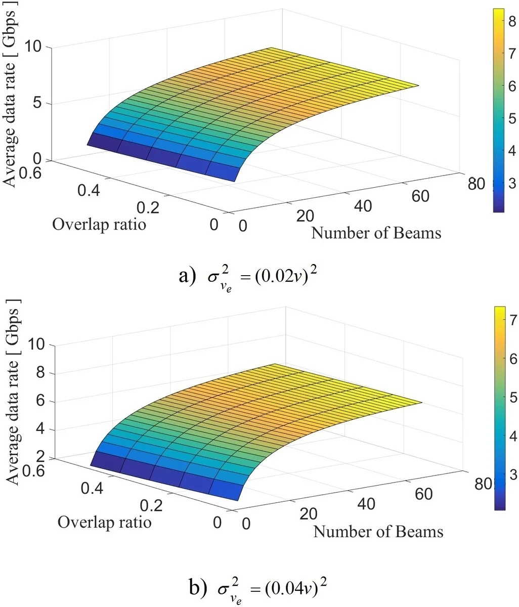
Both designs may incorporate an overlap between adjacent beams (0 %–30 % of the beamwidth) to mitigate speed‑estimation errors. The system model assumes a two‑lane highway, RSU height 7 m, vehicle height 1.5 m, carrier frequency 60 GHz, bandwidth 2.16 GHz, and a constant vehicle speed of 25 m/s (used only as a reference). The received power is expressed via a Friis‑type equation that includes antenna gain approximated as G_r(θ_b) ≈ π²/(θ_el θ_b). The instantaneous capacity follows Shannon’s formula C(t,θ_b)=B·log₂(1+ρ(t,θ_b)), where ρ is the SNR derived from the received power and noise floor (‑174 dBm/Hz plus NF).
The authors derive closed‑form expressions for the amount of data transmitted while a particular beam is active, taking into account the speed error v_e = ˆv – v. Positive and negative v_e are treated separately because they shift the beam‑switching instants forward or backward in time. The average data rate D̅ is obtained by integrating the capacity over the time each beam is correctly aligned, weighted by the probability density of v_e. Similarly, the average outage time T_out is derived by integrating the periods where the vehicle lies outside the active beam, again conditioned on v_e.
Numerical simulations explore the impact of N_b and the overlap ratio on two performance metrics: average data rate and average outage percentage. Key observations include:
- Data rate: The equal‑coverage design yields roughly 1.5× higher peak data rates than the equal‑beam design because narrower beams provide higher antenna gain. However, its performance degrades more sharply as σ²_v increases; the equal‑beam design is more robust to larger speed‑estimation errors.
- Outage time: As N_b grows, outage time also grows for both designs, but the increase is far steeper for equal‑coverage. This is due to the narrower beams leaving less margin for prediction errors. Consequently, the equal‑beam design consistently shows lower outage percentages.
To balance these conflicting objectives, the authors propose a Beam Design Efficiency (BDE) metric:
BDE = α·DataRate – β·Outage,
where α and β are scaling coefficients chosen so that the maximum achievable data rate maps to 1 and the minimum outage maps to 0 (solving two linear equations). The BDE is evaluated across N_b and overlap values under a representative error variance σ²_v = (0.04 v)². Results indicate a crossover point: for N_b ≤ 41 the equal‑coverage design achieves higher BDE, while for N_b ≥ 42 the equal‑beam design becomes superior. The same trend holds for both 0 % and 30 % overlap scenarios.
The paper’s contributions can be summarized as follows:
- Comprehensive analysis of how beamwidth, number of beams, and beam overlap affect mmWave V2I performance in the presence of realistic DSRC‑based position/speed estimation errors.
- Closed‑form expressions for average data rate and outage time that explicitly incorporate speed‑error statistics.
- Introduction of the BDE metric, providing a systematic way to trade off throughput against reliability and to select the appropriate beam design strategy based on error statistics and system constraints.
- Design guidelines: When estimation errors are small and the RSU can afford a moderate number of beams, equal‑coverage (narrow, high‑gain beams) is preferable for maximizing throughput. When errors are larger or a high number of beams is required (e.g., to cover a long RSU sector), equal‑beam designs with limited overlap yield lower outage and higher overall efficiency.
Overall, the work fills a gap in the literature by moving beyond the binary choice of “more beams = higher rate” and showing that, under realistic error conditions, an optimal balance must be struck. The proposed BDE framework can be extended to incorporate additional factors such as vehicle density, multi‑user scheduling, or adaptive beamwidth control, making it a useful tool for future mmWave V2I system design.
Comments & Academic Discussion
Loading comments...
Leave a Comment