An Efficient Adaptive Distributed Space-Time Coding Scheme for Cooperative Relaying
A non-regenerative dual-hop wireless system based on a distributed space-time coding strategy is considered. It is assumed that each relay retransmits an appropriately scaled space-time coded version of its received signal. The main goal of this pape…
Authors: Jamshid Abouei, Hossein Bagheri, Amir K. Kh
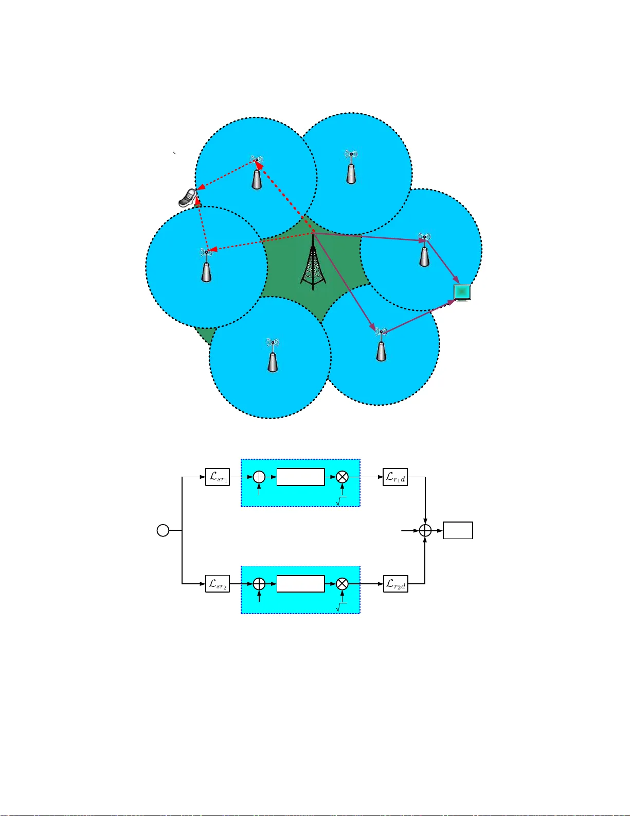
1 An Ef ficient Adapti v e Distrib uted S pace-T ime Coding Scheme for Cooperati v e Relaying Jamshid Abouei, Ho ssien Bagheri, and Amir K. Kha ndani Coding and Signal T r ansmission Labor atory (www .cst.uwaterloo. ca) Departmen t of Electrical and Comp uter Engine ering, University of W aterloo W aterloo , Ontario , Canada, N2L 3G1 T el: 519 -884- 8552 , Fax: 519-8 88-43 38 Emails: { jabouei, hb agheri, khan dani } @cst.uwaterloo. ca Abstract A non -regenerative dual-ho p wireless system based on a distributed space-time cod ing strategy is considered . It is assumed that each relay retra nsmits an app ropriately scaled space- time coded version of its rece i ved signal. The main goal of this pap er is to in vestigate a power allocation strategy in relay stations, which is based o n minimizing the ou tage probab ility . In the h igh sign al-to-no ise ratio regime for th e relay-destination link, it is shown that a thresh old-based power allocation scheme (i.e. , the relay remains silent if its channel gain with the source i s less than a prespecified threshold) is optimum. Monte- Carlo simulations sh ow that th e d erived o n-off power allocation scheme pe rforms close to optimum for finite signal-to-n oise ratio values. Numerical r esults demonstrate a d ramatic imp rovement in system perfor mance a s comp ared to the case that the relay station s forward their received signals with f ull power . I n addition, a hyb rid amplif y-and- forward/detect- and-forward sche me is prop osed for th e case that th e q uality of the source- relay link is go od. Fin ally , the robustness of the propo sed scheme in the presence of chann el estimation err ors is numerically evaluated. ∗ This work is financially supported by Nortel Networks and the corresponding matching funds by the Natural S ciences and Engineering Research Council of Canada (NSERC), and Ontario Centers of Excellence (OCE ). ∗ The material in this paper was presented in part at the 42nd Conference on IEEE Information Sciences and Systems (CIS S), Princeton Uni versity , Princeton, NJ, March 19-21 , 2008 [1]. 2 Index T erms Cooperative relayin g, space-time coding, ou tage prob ability , multi-hop wireless networks. I . I N T RO D U C T I O N A primary challenge in wireless networks is t o mitigate the effe ct of the multipath fading. Exploitin g techniques such as t ime, frequency and sp ace div ersity are the most eff ectiv e metho ds to combat t he channel fading. Du e to t he dramatic reduction in the size of w ireless devices along with the power and the cost limitatio ns, it is not practical to instal l mult iple antennas on mobile st ations. A heuristic solut ion to this problem is to u se a collection of distributed antennas belonging to mult iple users [2]–[4]. This ne w diversity scheme, referred to as cooperative div ersity (also k nown as cooperative r elayin g ), has attracted consi derable attention i n ad hoc and sensor wireless n etworks in recent years. In particular , t his approach is con sidered as an option in many wireless systems; including IEEE 802.16j mo bile mul tihop relay-based (MMR) networks. Unlike con ventional relaying sy stems that forward th e recei ved signal in a relay chain, cooperativ e relaying takes o ne step further; i.e., m ultiple relay nodes work together to achieve a better performance. Cooperativ e relay networks hav e been addressed from dif ferent perspecti ves; including capacity and outage probability analysis [2]–[7], resource allocation (e.g., power al location [8]), coding [9], relay selection [4], [10], etc. Central to the study of cooperative relay systems is the probl em of using d istributed space-time coding (DSTC) technique as well as effi cient power allocation schemes in regenerativ e and non-regenerati ve configurations [5], [11]–[18]. The first s tudy on using DSTC scheme in cooperativ e relay networks was framed in [5] where sev eral relay n odes transm it jointly t o the same receive r i n order to achie ve full sp atial dive rsity in terms of t he number of cooperating nodes. Reference [5] analyzes the outage capacity in the high si gnal-to-noise ratio (SNR) regime. Nabar et al . [11] analyze the pairwis e error p robability of an amp lify-and-forward (AF) single-relay system w hich relies on a DSTC scheme. In [12], the authors i n vestigate the high SNR uncoded bit-error rate (BER) of a two-r elay system usi ng 3 a switching schem e for QPSK modu lation. Scutari and Barbarossa [14] analyze the performance of regenerati ve relay networks with DSTC where th e error on t he source-relay link propagates into the s econd phase of the transm ission in t he relay-destination l ink. They show ho w to allocate t he transmission power between sou rce and relay to minimi ze the a verage BER. The BER o f sin gle and du al-hop non-regenerativ e relay s ystems with DSTC has been analyzed in [15] where diffe rent transmission policies are in vestigated in order to maximize the end-to-end SNR. The BER of regenerati ve relay networks using the DSTC scheme, along with different power allocation strategies over non-identical Ricean channels is analyzed i n [17]. Zhao et al. [8] introduce two power allocation algorithm s for AF relay networks to minimi ze the outage probability without the DSTC scheme. In this paper , we consider a dual-hop wireless sys tem consi sting of a source, two parallel relay stations (RS) and a destination. Assumi ng that each relay kn ows its channel with the source, the RSs collaborate wit h each other by t ransmitting a space-time coded (STC) version of their recei ved signals to the destination. In such configuration, if the instantaneous recei ved SNR of the relays are un balanced, the performance of th e system degrades substantially . T o overcome this problem, an adaptive dis tributed space-time codi ng (ADSTC) meth od is propo sed, in which instead of transmitt ing th e noisy signal at each relay wit h full power , the RS retransmits an appropriately scaled STC version of the recei ved si gnal. The main goal i s to optim ize t he scaling factor based on the channel-state information (CSI) av ail able at each relay to min imize the outage probability . The above scheme is differe nt from the powe r allocation algorithms st udied in [8]; primarily we utilize an ADSTC scheme based on the CS I av ailable at each relay , while in [8], no DSTC scheme i s u sed. In o ur scheme, no informati on is exchanged between the relay stations. Thi s is to be contrasted with the algorithms proposed in [15], in which the relays need to e xchange some information with each other in order t o establish which relay transm its. In addition, our scheme is differ ent from the power allo cation st rategies in [19]–[21], in whi ch the b est relays 4 are selected based on the feedbac k from the destination. In the high SNR regime for the relay-destinatio n link, it i s shown th at a t hreshold-based power allocation scheme (i.e., the relay remains si lent if it s channel gain wi th the so urce is less than a prespecified threshol d) is optimum. Numerical results in dicate that the derived on- off power allocation scheme provides a significant performance improvement as compared to the case that the RSs forward their receive d signals wit h full power all the time. T o furth er improve the s ystem p erformance when t he q uality o f the source-relay link is goo d, a hybri d amplify-and-forward/detect-and-forward scheme is prop osed. In the proposed scheme, we assume that perfect channel knowledge is av ailable at the receiv er . In practice, h owe ver , the performance of the sys tem is degraded due t o the channel est imation error . In the last part of this paper , we address this iss ue and ev aluate t he robustness of the proposed scheme i n t he presence of channel estimation errors. The rest of t he paper is or ganized as follows. In Section II, the system mod el and objectives are described. The performance of the s ystem is analyzed in Section III. In Section IV, the simulatio n results are presented. Th e ef fect of channel estimat ion errors on the propo sed schem e is e valuated i n Section V. Finally , conclusio ns are drawn in Section VI. Notations: Throughout the paper , we use boldface capital and lower case let ters t o denote vectors and m atrices, respectiv ely . k a k indicates the Eu clidean norm of the vector a . The conjugate and conjugated transpositio n of a comp lex matrix A are denoted by A ∗ and A † , respectiv ely . The n × n identit y matrix is denoted by I n . A circularly symmetric comp lex Gaussian random variable (r .v .) is represented by Z = X + j Y ∼ C N (0 , σ 2 ) , where X and Y are independent and identically distributed (i.i.d.) normal r .v . ’ s with N (0 , σ 2 2 ) . Also, A → B represents t he link from n ode A to node B . Finally , P { . } and E [ . ] denote the probabil ity of the giv en ev ent and th e expectation operator , respectiv ely . 5 I I . S Y S T E M M O D E L A N D O B J E C T I V E S In this work, we consider a cooperative relay sy stem consis ting o f one base station (BS), multiple relay s tations rando mly located wit hin the network region, and mult iple mobi le st ations (MSs) (Fig. 1-a). All the nod es are assumed to have a single antenna. The relay stations are assumed to be non -regenera tive, i.e., they perform some simple operatio ns on the recei ved signals and forward them to the M Ss [15]. Also, it is assumed that no inform ation is exchanged between the relays. In this set-up, each pair o f the relay stati ons cooperate with each other to forward their rec eiv ed signals from the source t o the desti nation 1 (Fig. 1-b). The channel model is assumed to be frequency-flat block Rayleigh fading with the path loss ef fect. L et us denote the channel coef ficients of t he links S → RS i and RS i → D as L sr i and L r i d , i = 1 , 2 , respective ly . In t his case, the channel gain between S and RS i is represented by g sr i , |L sr i | 2 = Γ sr i | h sr i | 2 , where Γ sr i , 10 − Υ sr i / 10 is the gain asso ciated with the path loss Υ sr i [dB], and the complex random variable h sr i is the fading channel coefficient. Similarly , the channel gain of the l ink RS i → D is represented by g r i d , |L r i d | 2 = Γ r i d | h r i d | 2 , where Γ r i d , 10 − Υ r i d / 10 and h r i d are the gain associated with the path l oss Υ r i d [dB] and the channel fading coef ficient, respectiv ely . Under the Rayleigh fading channel mod el, | h sr i | 2 and | h r i d | 2 are exponentially dist ributed wi th unit mean (and unit var iance). Also, the background noise at each recei ver is assumed to be a dditive white Gaussian noise (A WGN). For this model, c ommuni cation between S and D is performed based on the following steps: i) Data T ransmis sion: This is performed i n two ph ases and throug h two hop s. In the first phase, the source broadcasts the symbols x [1] and x [2] (normalized to have unit energy) to the RSs in t wo cons ecutiv e tim e slots and ov er one frequency band. The recei ved discrete-time baseband signal at RS i is gi ven by u i [ k ] = p P s L sr i x [ k ] + n r i [ k ] , i = 1 , 2 , (1) where k = 1 , 2 , represents the transmi ssion time index, P s is th e transmit power of the source 1 In the sequel and for the sak e of simplicity of notations, the BS and the MS are deno ted by the source (S ) and the destination (D), respecti vely . 6 BS MS 1 RS 2 RS MS (a) S STC E NCODER 1 r n D ECODER 2 r n STC E NCODER R ELAY STATION #1 R ELAY STATION #2 d n ]) 2 [ ], 1 [ ( x x ]) 2 [ ], 1 [ ( x x 1 u 2 u 1 α 2 α (b) Fig. 1. a) Coop erativ e relay network, an d b) a discrete-time b aseband equ iv alen t mod el of a d ual-ho p wireless system. 7 T ABLE I T R A N S M I S S I O N P O L I C Y AT R S S RS 1 RS 2 1 st time sl ot √ α 1 e − j θ sr 1 y 1 [1] √ α 2 e − j θ sr 2 y 2 [2] 2 nd time sl ot − √ α 1 ` e − j θ sr 1 y 1 [2] ´ ∗ √ α 2 ` e − j θ sr 2 y 2 [1] ´ ∗ and n r i [ k ] ∼ C N (0 , N 0 ) is the background noise at RS i . The channel gains are assumed to remain constant over two successive symb ol transm issions. Also, we assu me that RS i has perfect information about h sr i . T o satisfy t he power constraints at the RSs, we normalize u i [ k ] to r E x h | u i [ k ] | 2 h sr i i , i = 1 , 2 [8], [16], [22]. Thus, (1) can be written as y i [ k ] = 1 p P s g sr i + N 0 p P s L sr i x [ k ] + n r i [ k ] , (2) for i, k = 1 , 2 . Using the fac t that x [ k ] is independent of n r i [ k ] , it yields E h | y i [ k ] | 2 h sr i i = 1 . In the second phase, the RSs cooperate with each other and forward the s pace-time coded version of their receive d noisy signals to t he d estination over the same or another frequency band 2 (T able I). In such configuration , RS i multipli es y i [ . ] by the scaling factor √ α i , where 0 ≤ α i ≤ 1 . It should be n oted that th e phase of S → RS i link, d enoted by θ sr i , i s compensated at RS i through multiplying the recei ved signal by the factor e − j θ sr i = h ∗ sr i | h sr i | [15], [16] 3 . In genera l, due to the different distances b etween each RS and D, t he arriv al ti me of the receiv ed sign als at D may be diffe rent. The cyclic prefix added to t he orthogo nal frequency-di vision multi plexing (OFDM) symbols mitigates t he effect of the time delay , and it preserves the o rthogonality of the tones. Th us, we can apply the above s cheme in each tone. In each time sl ot, D recei ves a superpositi on o f the transm itted signals by RSs. T o this end, 2 It is assumed that RSs use the same transmission protocol based on t he IE EE 802.16j t ime division duple x (TDD) frame structure [23]. 3 W e will exp lain the main reason for using the phase compensation shortly . 8 the recei ved signals at D in the first and the second tim e sl ots are given by r d [1] = √ α 1 e − j θ sr 1 y 1 [1] p P r 1 L r 1 d + √ α 2 e − j θ sr 2 y 2 [2] p P r 2 L r 2 d + n d [1] , (3) r d [2] = − √ α 1 e − j θ sr 1 y 1 [2] ∗ p P r 1 L r 1 d + √ α 2 e − j θ sr 2 y 2 [1] ∗ p P r 2 L r 2 d + n d [2] , (4) respectiv ely , where P r i is the transmit power of RS i and n d [ k ] ∼ C N (0 , N 0 ) represents the background noise at t he destination. It should be noted that du e t o the lar ge distance between S and D (or due to t he strong shadowing), we ignore t he receiv ed si gnal of the d irect link S → D. Substituting (2) in (3) and (4) yields r d [1] = L ′ 1 x [1] + L ′ 2 x [2] + z d [1] , (5) r d [2] = L ′ 2 x ∗ [1] − L ′ 1 x ∗ [2] + z d [2] , (6) where L ′ i , L r i d s α i P s P r i g sr i P s g sr i + N 0 , i = 1 , 2 , (7) and z d [1] , L ′ 1 √ P s L sr 1 n r 1 [1] + L ′ 2 √ P s L sr 2 n r 2 [2] + n d [1] , (8) z d [2] , − L ′ 1 √ P s L ∗ sr 1 n ∗ r 1 [2] + L ′ 2 √ P s L ∗ sr 2 n ∗ r 2 [1] + n d [2] . (9) It is observed that z d [1] is independent of z d [2] and E h | z d [1] | 2 h i = E h | z d [2] | 2 h i = σ 2 , where h , [ h sr 1 , h sr 2 , h r 1 d , h r 2 d ] and σ 2 , |L ′ 1 | 2 g sr 1 + |L ′ 2 | 2 g sr 2 N 0 P s + N 0 . (10) ii) Decoding Process: Amplify-and-forward r elay networks require full C SI at the destination to coherently decode the recei ved signal s. The requi red channel in formation can be acquired by transmittin g pilot signals 4 . According to the Alamouti scheme [24], we ha ve r d [1] r ∗ d [2] = L ′ 1 L ′ 2 L ′ ∗ 2 −L ′ ∗ 1 x [1] x [2] + z d [1] z ∗ d [2] , 4 Channel estimati on can be done in two st eps. In the first step, RS i transmits a pilot sequence to provide L r i d to D. In the second step, S transmits another pilot sequence to pro vide L sr i to RS i and L sr i L r i d to D. In this step, RSs work as usual. 9 or equivalently r d = L x + z d . It is worth mention ing that du e to the conjugate terms in (4), the heuristic phase compensati on at RSs (i.e., e − j θ sr i = h ∗ sr i | h sr i | ) is done to preserve the orthogonal property of the processing matrix L , i. e., L † L = |L ′ 1 | 2 + |L ′ 2 | 2 I 2 , Λ I 2 . Th us, we can use the A lamouti scheme. Also, upon this phase com pension assump tion and the AF scheme at the relay nodes, the above s cenario is con verted to th e original STC prob lem. Hence, the menti oned decoder is maximum likelihood (ML) optimal. F or this configuration, the input of the ML decoder is gi ven by [25] ˜ r d , L † r d (11) = Λ x + ˜ z d , (12) where ˜ z d , L † z d . In this case, the t wo-dimensional d ecision rule used in the M L d ecoder is ˆ x = ar g min ˆ x ∈ S 2 k ˜ r d − Λ ˆ x k 2 , (13) where S 2 denotes the correspond ing signal constellatio n s et. Let us denote the a verage signal-to -noise ratios of S → RS i and RS i → D by SNR sr i , P s N 0 Γ sr i and SNR r i d , P r i N 0 Γ r i d , i = 1 , 2 , respective ly . Here, we assume that SNR sr i and SNR r i d are known at RS i . Assum ing h sr i is av ailable at RS i , the main objective is to select the optimum factor α i such that t he out age probability is minimi zed. I I I . P E R F O R M A N C E A N A L Y S I S In this secti on, we characterize the performance of the model described i n Section II in t erms of th e outage probability . For this purpose, we first obtain t he ins tantaneous end-to-end SNR. Then, we deri ve an expression for the outage probability in the high SNR r i d regime. Since, m atrix L | h is determinist ic and notin g that E h z d z † d | h i = σ 2 I 2 , we conclude from (12) that E h ˜ z d ˜ z † d | h i = E h L † z d z † d L | h i = Λ σ 2 I 2 . (14) 10 In fact, the noise vector ˜ z d | h is a wh ite Gaussi an nois e. Denoting γ as the instantaneous end- to-end SNR and using (12), w e ha ve γ = Λ 2 Λ σ 2 = |L ′ 1 | 2 + |L ′ 2 | 2 |L ′ 1 | 2 g sr 1 + |L ′ 2 | 2 g sr 2 N 0 P s + N 0 . (15) In the outage-based transmissio n frame work, the outage occurs whenev er γ is less than a threshold γ t > 0 . In t his case, the outage probability can be expressed as P out , P { γ < γ t } . (16) The goal is to mini mize t he objective function defined in (16) subject to 0 ≤ α i ≤ 1 , i = 1 , 2 . The global optimal solution can be obtained through centralized algorithms. This is in con trast to the distributed scheme proposed in Section II. Since, it is di f ficult to directly compute the exact expression for t he outage probabili ty , we first present the outage probability in the h igh SNR r i d regime. Then, we propo se an optimum d istributed power allocation strategy for the RS i to minimize t he ob jectiv e function in (16). Defining g , h | h sr 1 | 2 = v 1 , | h sr 2 | 2 = v 2 i , and using the fact that the link S → RS 1 is independent of t he l ink S → RS 2 , the outage probabilit y is given by P out = E g [Ω( g )] = Z ∞ 0 Z ∞ 0 Ω( g ) e − v 1 e − v 2 dv 1 dv 2 , (17) where Ω( g ) , P { γ < γ t | g } . It i s concluded from (7) and (15) that Ω( g ) = P X 1 v 1 + X 2 v 2 ( X 1 Γ sr 1 + X 2 Γ sr 2 ) N 0 P s + N 0 < γ t g , (18) where X i , F ( v i ) | h r i d | 2 with F ( v i ) , α i P s P r i Γ sr i Γ r i d P s Γ sr i v i + N 0 , i = 1 , 2 . (19) Under the Rayleigh fading channel model, X i | v i is exponentially distributed with parameter 1 F ( v i ) and the probabil ity densi ty function (pdf) f X i | v i ( x i | v i ) = 1 F ( v i ) e − x i F ( v i ) U ( x i ) , (20) 11 where U ( . ) is the unit step function. In the hi gh SNR r i d regime (i.e., P r i Γ r i d ≫ P s Γ sr i and P r i Γ r i d ≫ N 0 , i = 1 , 2 ), (18) can be simpl ified to Ω( g ) ≈ P X 1 v 1 + X 2 v 2 ( X 1 Γ sr 1 + X 2 Γ sr 2 ) N 0 P s < γ t g (21) = P v 1 − ξ Γ sr 1 X 1 < ξ Γ sr 2 − v 2 X 2 g , (22) where ξ , N 0 P s γ t . Depending on the va lues of v 1 and v 2 , we have the following cases: Case 1: v 1 < ξ Γ sr 1 and v 2 < ξ Γ sr 2 In th is case, (22 ) can be written as Ω( g ) = P { Z > φ | g } ( a ) = 1 , (23) where Z , X 1 X 2 and φ , ξ Γ sr 2 − v 2 v 1 − ξ Γ sr 1 . (24) In the above equations, ( a ) follows from the fact t hat for v 1 < ξ Γ sr 1 and v 2 < ξ Γ sr 2 , φ is negati ve and this results i n P { Z ≤ φ | g } = 0 . Case 2: v 1 > ξ Γ sr 1 and v 2 < ξ Γ sr 2 From (22), we hav e Ω( g ) = P { Z < φ | g } , (25) where φ is posit iv e. It can be shown that the pdf of the random v ariable Z condi tioned on the vector g is obtained as [26] f Z | g ( z | g ) = F ( v 1 ) F ( v 2 ) ( F ( v 2 ) z + F ( v 1 )) 2 U ( z ) . (26) Thus, (25) can be written as Ω( g ) = Z φ 0 f Z | g ( z | g ) dz (27) = F ( v 2 ) φ F ( v 2 ) φ + F ( v 1 ) . (28) Case 3: v 1 < ξ Γ sr 1 and v 2 > ξ Γ sr 2 12 In th is case, (22 ) can be written as Ω( g ) = P { Z > φ | g } (29) = 1 − P { Z ≤ φ | g } (30) ( a ) = F ( v 1 ) F ( v 2 ) φ + F ( v 1 ) , (31) where φ i s p ositive and ( a ) comes from (26) and (28). Case 4: v 1 > ξ Γ sr 1 and v 2 > ξ Γ sr 2 In th is case, since φ is ne gative , we ha ve Ω( g ) = P { Z < φ | g } = 0 . (32) Now , we can use the abov e results to simplify the outage probabilit y given in (17) for P r i Γ r i d ≫ P s Γ sr i and P r i Γ r i d ≫ N 0 , i = 1 , 2 . Usin g (23 ), (28), (31) and (32), we have P out = Z ∞ 0 Z ∞ 0 Ω( g ) e − v 1 e − v 2 dv 1 dv 2 (33) = Z ξ Γ sr 1 0 Z ξ Γ sr 2 0 1 e − v 1 e − v 2 dv 1 dv 2 + Z ξ Γ sr 1 0 " Z ∞ ξ Γ sr 2 F ( v 1 ) e − v 2 F ( v 2 ) φ + F ( v 1 ) dv 2 # e − v 1 dv 1 + Z ∞ ξ Γ sr 1 " Z ξ Γ sr 2 0 F ( v 2 ) φe − v 2 F ( v 2 ) φ + F ( v 1 ) dv 2 # e − v 1 dv 1 + Z ∞ ξ Γ sr 1 Z ∞ ξ Γ sr 2 0 e − v 1 e − v 2 dv 1 dv 2 (34) = 1 − e − ξ Γ sr 1 1 − e − ξ Γ sr 2 + Z ξ Γ sr 1 0 " Z ∞ ξ Γ sr 2 e − v 2 F ( v 2 ) φ + F ( v 1 ) dv 2 # F ( v 1 ) e − v 1 dv 1 + Z ξ Γ sr 2 0 " Z ∞ ξ Γ sr 1 φe − v 1 F ( v 2 ) φ + F ( v 1 ) dv 1 # F ( v 2 ) e − v 2 dv 2 . (35) Now , the main objecti ve is to find the optimum scaling f actor α i (or equiv alentl y F ( v i ) defined in (19)) th at minim izes the outage probability obtained i n (35). Since for v 1 < ξ Γ sr 1 and v 2 > ξ Γ sr 2 , φ , ξ Γ sr 2 − v 2 v 1 − ξ Γ sr 1 > 0 , it is concluded that the second term in (35) is a nonnegativ e value. W ith a si milar argument, the t hird term in (35) is nonnegativ e as well. Also , w e use the fact that ξ , N 0 P s γ t > 0 . Hence, to minimi ze (35), it is su f ficient to have Z ξ Γ sr 1 0 " Z ∞ ξ Γ sr 2 e − v 2 F ( v 2 ) φ + F ( v 1 ) dv 2 # F ( v 1 ) e − v 1 dv 1 = 0 , (36) Z ξ Γ sr 2 0 " Z ∞ ξ Γ sr 1 φe − v 1 F ( v 2 ) φ + F ( v 1 ) dv 1 # F ( v 2 ) e − v 2 dv 2 = 0 . (37) 13 Noting that R ∞ ξ Γ sr 2 e − v 2 F ( v 2 ) φ + F ( v 1 ) dv 2 and R ∞ ξ Γ sr 1 φe − v 1 F ( v 2 ) φ + F ( v 1 ) dv 1 are posi tive , the optimum func- tion F ( v i ) that sati sfies (36) and (37) (or equivalently min imizes (35)) is F ( v i ) = 0 , for 0 < v i < ξ Γ sr i , i = 1 , 2 (38) In this case, min P out = 1 − e − ξ Γ sr 1 1 − e − ξ Γ sr 2 (39) ( a ) = 1 − e − γ t SNR sr 1 1 − e − γ t SNR sr 2 , (40) where ( a ) comes from ξ , N 0 P s γ t and SNR sr i , P s N 0 Γ sr i . Using (19) and (38), we come up with the following result: ˆ α i = 0 , 0 < g sr i < ξ , i = 1 , 2 , (41) where ˆ α i is the opti mum scaling factor that mi nimizes the outage probabilit y . In other words, the relay remai ns silent if its channel gain with t he source is less than the th reshold le vel ξ . Note that we are not concerned with the com putation of the exact v alues of t he scaling factors at the relay nod es, i.e., ˆ α i for v i ≥ ξ Γ sr i , as long as P r i Γ r i d ≫ P s Γ sr i and P r i Γ r i d ≫ N 0 , i = 1 , 2 . Remark 1- The case of high SNR sr i is similar to t he traditional STC problem . Therefore, the optimum po wer allo cation policy for relay stations is the full powe r t ransmission . I V . N U M E R I C A L R E S U L T S In th is section, we present some Mont e-Carlo simulation results to ev aluate the impact of α i on the sys tem performance. W e use the propagation model with intermediate path-loss cond ition (i.e., terrain type B for su burban, above roo f top (AR T) to below roof top (BR T)) provided b y W iMAX Forum and IEEE 802.16j relay W orking Group (WG) [27 ], i.e., Υ ij , 20 log 10 4 π d ij λ , d ij ≤ d ′ 0 K + 1 0 β log 10 d ij d 0 + ∆Υ f + ∆Υ h t , d ij > d ′ 0 , where Υ ij , − 10 log 10 Γ ij is the path loss between nodes i and j expressed in dB, and • d ij is the di stance betw een nodes i and j , 14 T ABLE II S Y S T E M E V A L UAT I O N P A R A M E T E R S [ 2 7 ] Parameter s V alues Carrier frequen cy 2.4 GHz SNR r i d , i = 1 , 2 0 − 40 dB d 0 100 m Antenna height BS=32 m, RS=15 m, MS=1.5 m Distance between S and RS d sr 1 = 5 km, d sr 2 = 8 km Distance between RS and D d r 1 d = 2 km, d r 2 d = 1 km Path loss expon ent parameters a = 4 , b = 0 . 0065 , c = 17 . 1 • λ is the wave length, • β is the path loss exponent, • d 0 is the reference distance, • d ′ 0 , d 0 10 − ∆Υ f +∆Υ h t 10 β • ∆Υ f is the correction factor for the carrier frequenc y f , • ∆Υ h t is the correction factor for the RS/MS BR T antenna height h t , • K , 20 log 10 4 π d ′ 0 λ . For this model, β , ∆Υ f and ∆Υ h t are giv en as [27] β , a − bh b + c h b , ∆Υ f , 6 log 10 f ( MHz ) 2000 , ∆Υ h t , − 10 log 10 h t 3 , h t ≤ 3 m − 20 log 10 h t 3 , h t > 3 m , respectiv ely , where h b represents the height of BS/RS AR T antenna. Using the system parameters listed in T able II, the desired SNR sr i and SNR r i d are obtained through adjusting P s N 0 and P r i N 0 , respectiv ely . 15 W e consi der so me forms of the scaling f actors α i in terms of g sr i . In the full power scheme, each relay retransmits its receiv ed si gnal with full p ower (i.e., α i = 1 ), regardless o f the value of g sr i . For the on-off power s cheme, RS i with g sr i above certain threshol d transmits at full power , otherwise it remains silent, i.e., α i = 0 . W e also consider the piece wise li near function scheme, in which t he scali ng f actor α i is defined as α i , 0 , g sr i < τ 1 1 τ 2 − τ 1 g sr i − τ 1 τ 2 − τ 1 , τ 1 ≤ g sr i < τ 2 1 , g sr i ≥ τ 2 , (42) where the op timum values of τ 1 and τ 2 are obtained using an exhaustiv e search to mini mize the outage probabil ity . This functio n can approximate a lar ge class of appropriate functions 5 by adjus ting τ 1 and τ 2 . In additio n, we use the ML decoder at D to fully exploit the diversity adva ntage of the proposed scheme. Fig. 2 compares the outage probability of t he aforementio ned power schemes versus γ t for diffe rent values of SNR r 1 d = SNR r 2 d , SNR r d . The results are obtained by a veraging over 1 0 6 channel realizations. W e can observe a significant performance improvement for the on-off po wer scheme in compariso n with the full powe r scenario, as SNR r d increases. For instance, 1 0 dB gain is obtained u sing the on-off powe r strategy for SNR r d = 40 dB and P out = 10 − 2 with respect to the full power scheme. Also, it can be seen that the optimi zed piecewise linear functi on performs close to the on-off scheme. T abl e III shows the o ptimum threshold lev el of the on-off power scheme expressed in dB for different v alues of γ t and SNR r d , and SNR sr 1 = SNR sr 2 = 25 dB. It is int eresting to note th at the o ptimum threshold values o btained by e xhaustive s earch are close to ξ (dB) = γ t (dB) − SNR sr i (dB) obtained in Section III. In Fig. 3, we plot the outage probabiliti es of the centralized scheme, iterative algorithm and the on-off power allo cation strate gy with the threshold ξ obtained in Section III. In the centralized approach, th e opt imum α 1 and α 2 are o btained throu gh an exhaustive search to minim ize the 5 The optimum function should hav e small v alues when the channel is weak and should increase up to 1 as the channel gain increases. 16 0 5 10 15 20 25 30 35 10 −4 10 −3 10 −2 10 −1 10 0 γ t [dB] Outage Probability SNR sr1 =25 [dB], SNR sr2 =15 [dB] SNR rd =0 dB, Full Power SNR rd =0 dB, On−Off SNR rd =20 dB, Full Power SNR rd =20 dB, On−Off SNR rd =40 dB, Full Power SNR rd =40 dB, On−Off SNR rd =40 dB, Piecewise Linear Fig. 2. Outage proba bility versus γ t for different strateg ies. T ABLE III O P T I M U M T H R E S H O L D L E V E L F OR T H E O N - O FF P O W E R S C H E M E SNR r d = 0 dB SNR r d = 10 dB SNR r d = 20 dB S NR r d = 30 dB SN R r d = 40 dB γ t = 0 dB -25 -25 -25 -25 -25 γ t = 10 dB -13 -15 -15 -15 -15 γ t = 20 dB 0 -1.5 -5 -5 -5 γ t = 30 dB 0 0 0 0 0 outage probability . In the iterative scheme, t he algorithm starts from an ini tial value of α 1 for e very g sr i . Then, for each value of g sr 2 , α 2 is obtained such that t he outage probability i s minimized. This process continues until the algori thm con ver ges. The results in Fig. 3 show that the d iff erence in performance between t he propo sed on-off power scheme and the centralized approach is small. Therefore, the on -of f s cheme ob tained by the asym ptotic analysis in Section III is alm ost op timal. Fig. 4 plots the uncoded BER versus SNR r d for di f ferent power schemes and BPSK constel- lation. W e observe an error floor i n the figure for the hi gh SNR r d . This can be at tributed to the amplified noise receive d at the destination through the R → D link. In this case, the p erformance 17 0 5 10 15 20 25 30 10 −4 10 −3 10 −2 10 −1 10 0 γ t [dB] Outage Probability SNR sr1 =25 [dB], SNR sr2 =15 [dB] and SNR rd =20 [dB] On−Off with the threshold ξ On−Off with Optimum Threshold Iterative Algorithm Centralized Approach Fig. 3. Outage proba bility versus γ t for different po wer schemes. is gov erned by SNR sr i , i = 1 , 2 . It shoul d be noted t hat by using the on-off p ower allocati on strategy at RSs, we can save the energy i n the s ilent m ode. Howe ver , simu lation results implies th at the power s a ving gain in the on-off power s cheme is negligibl e. This is du e to the fact that for mid-SNR sr i region, P O N , Pr { g sr i > g T h } ≥ 0 . 95 , where g T h is the optim um threshold le vel that m inimizes the BER. Fig. 5-a illust rates the frame-error rate (FER) versus ( E b / N 0 ) r d , energy per bit to noise densi ty ratio, using the standard turbo code [28] with the rate of 1 / 3 and for different fun ctions of α i , BPSK constellat ion and the frame length of 957 bits . Also, Fig. 5-b illus trates the FER versus ( E b / N 0 ) r d using the con volutional code (introduced in s ection 8 . 4 . 9 . 2 . 1 of the IEEE 802.1 6e standard [29]) w ith th e rate of 0 . 5 and the frame length of 576 bits. Com pared to t he full power scheme, the simulation resul ts sho w a significant improvement in the sy stem performance with the on-off power scheme. A lso, it is observed from the simulati on that the trend of the FER for 18 0 5 10 15 20 25 30 35 40 45 50 10 −6 10 −5 10 −4 10 −3 10 −2 10 −1 SNR rd [dB] BER SNR sr 1 =25 [dB], SNR sr 2 =15 [dB] and BPSK constellation Piecewise Linear Function On−Off Power Scheme Full Power Fig. 4. Uncoded BER versus SNR r d for dif ferent power schemes. higher order constell ations i s similar to the BPSK case [26]. Up to now , we hav e shown that the near -optimal power allocation in each relay in the AF mod e is the threshold-based on-off po wer scheme. T o further im prove the system performance when the quality of S → RS i is good, the detect-and-forward (DF) scheme is su ggested to eliminate the am plified noise at the RS. A hybrid thr eshold-based AF/DF scheme characterized by two threshold le vels T 1 and T 2 is described as follows: 1- For g sr i ≤ T 2 , RS i performs the on-off po wer scheme dev eloped in Section III. 2- For g sr i > T 2 , RS i detects x [ k ] , k ∈ { 1 , 2 } , from t he receiv ed signal and forwards the detected symbol ˆ x [ k ] to the destination. Fig. 6 com pares the FER of diffe rent transmissi on strategies in t he RSs for the con volutional code with Q PSK mod ulation and the frame length of 576 bit s. In the pure full power schem e, independent of the channel gain g sr i , each RS i transmits with full power all t he time. For completeness, we also consider the threshold -based DF scheme, in wh ich for g sr i less than a prescribed threshold, RS i remains silent, otherwise it switches to the DF m ode. It is observed that the performance of the hybrid threshold-based AF/DF schem e is the same as t he t hreshold- 19 0 5 10 15 20 25 30 35 40 10 −5 10 −4 10 −3 10 −2 10 −1 (E b /N 0 ) rd [dB] FER (E b /N 0 ) sr 1 =(E b /N 0 ) sr 2 =25 [dB] 0 5 10 15 20 25 30 35 40 10 −6 10 −5 10 −4 10 −3 10 −2 10 −1 (E b /N 0 ) rd [dB] FER (E b /N 0 ) sr 1 =(E b /N 0 ) sr 2 =25 [dB] Full Power On−Off Piecewise Linear Full Power On−Off Piecewise Linear (a) Turbo Code (b) Convolutional Code Fig. 5. FER versus ( E b / N 0 ) r d for different power schemes and for a) turbo code wi th the rate 1 / 3 b) con volutiona l code wit h the rate 1 / 2 . based AF on-off power scheme and both of them are bett er than the pu re full power and the threshold-based DF schem es. V . I M P A C T O F C H A N N E L E S T I M A T I O N E R RO R Throughout this paper , it is assumed that perfect channel knowledge is a vailable at the recei ver . In practice, howe ver , the channel estimatio n at the recei ver is often im perfect. Thus, the performance of the sys tem is degraded du e to the channel esti mation error 6 . In this secti on, we e valuate the FER degrada tion of the prop osed scheme due to the imperfect channel estim ation. T o handle that, a pilot-based channel estimation technique is assumed, where pilot sequences are inserted at th e beginning of each block. It is assu med that the p ilot sequences have the same ener gy as data symbols. In thi s case, the channel esti mation process is performed at the beginning 6 Such a problem has been first studied by Al amouti [24] and T arokh [ 30] in STC-based systems. This line of work is further extend ed for different structures of the receiv er (See [31] and i ts references). 20 0 5 10 15 20 25 30 10 −4 10 −3 10 −2 10 −1 (E b /N 0 ) rd [dB] FER (E b /N 0 ) sr 1 =(E b /N 0 ) sr 2 =20 [dB] Pure Full Power−AF Threshold−Based DF Hybrid Two Threshold−Based AF−DF One Threshold−Based On−Off Fig. 6. FER versus ( E b / N 0 ) r d for differen t transmission strategies and for con volutional code with the rat e 1 / 2 , ( E b / N 0 ) sr = 20 dB and for QP SK. of each block and the esti mated value remains constant over the block. T his assumpti on is valid under the frequency-flat Rayleigh fading channel model, where the multipath channel coefficients change slowly and are consi dered const ant. Due to the imperfect channel estimation, th e channel fading coefficients can be expressed as ˆ h sr i = h sr i + e sr i , (43) ˆ h r i d = h r i d + e r i d , (44) for i = 1 , 2 , where e sr i and e r i d represent the channel est imation errors w hich are modeled as independent compl ex Gaussian random variables with zero means and variances ϑ sr i and ϑ r i d , respectiv ely . W e assume that th e channel estimation error has the variance equal to t he in verse of the signal-to-noise ratio of the corresponding l ink [30], [32], [33], i.e., ϑ sr i = 1 / SNR sr i and ϑ r i d = 1 / SNR r i d . Fig. 7 shows t he FER performance of the full power and the on-off power schemes versus SNR r d for pe rfect and imperfect CS I situations. W e observe that for the low SNR r d , the rob u stness of the on-of f power scheme is clos e t o the full power case. Howe ver , for high SNR r d regime, 21 0 5 10 15 20 25 30 35 40 10 −4 10 −3 10 −2 10 −1 10 0 SNR rd [dB] Frame−Error−Rate (FER) SNR sr 1 =SNR sr 2 =20 [dB] Full Power− Perfect CSI On−Off− Perfect CSI Full Power− Imperfect CSI On−Off− Imperfect CSI Fig. 7. FER versus SNR r d for the full po wer and the on-off power all ocation schemes for perfect and imperfect CSI. the full power scheme is mo re robust to channel estimation errors than the on-of f power schem e. This is due t o t he fact that in t he on-off scheme, each relay i requires CSI of the link S → RS i for scaling f actor comp utation. It is obvious that in this case, imperfect CSI further d eteriorates the performance. Note that at low SNR r d , the performance is governed by the second link. In this case, CSI of the l ink RS i → D becomes equally important i n both schemes. V I . C O N C L U S I O N In this paper , a non-regenerati ve dual-hop wireless system based on a distributed space-time coding strategy is considered. It is assum ed that each relay forwards an appropriately scaled space-time coded ve rsion of i ts recei ved signal. In the high SNR r i d , it has been shown that the optimum power allocation strategy in each RS i which mi nimizes the outage probability is to remain silent, if g sr i is less than a prespecified threshol d lev el. Simulation results show that the threshol d-based on-off power scheme performs clo se to opt imum for finite SNR va lues. Numerical results demonstrate a dramati c improvement in system performance as compared to the case that the relay stations forward their recei ved signals with full power . The practical adva ntage of usi ng this protocol i s that it does not alter the Alam outi decoder at the desti nation, 22 while it slig htly m odifies the relay operation. A C K N OW L E D G M E N T The authors would like to thank S. A. Motahari, V . Pourahmadi and S. A. Ahmadzadeh of CST Lab . for the helpful discussions. R E F E R E N C E S [1] J. Abouei, H. Bagheri, and A. K. Khandani, “ An efficient adapti ve distributed space time coding scheme for cooperati ve relaying, ” in P r oc. IE EE 42nd Confer ence of Information Sciences and Systems (CISS’08) , Princeton Uni versity , Princeton, NJ, USA, March 2008. [2] A. Sendonaris, E. Erkip, and B. Aazhang, “User cooperation dive rsity: Part I system description, ” IEEE T ran s. on Commun. , vol. 51, no. 11, pp. 1927–1938, Nov . 2003. [3] A. Sendonaris, E. Erkip, and B. Aazhang, “User cooperation div ersity: Part II implementation aspects and performance analysis, ” IEEE T ran s. on Commun. , vo l. 51, no. 11, pp. 1939–194 8, Nov . 2003. [4] J. N. Laneman, D. N. C. Tse, and G . W . W ornell, “Cooperati ve di versity i n wireless network s: Efficient protocols and outage beha vior , ” IEEE T rans. on Inform. T heory , vol. 50, no. 12, pp. 3062– 3080, Dec. 2004. [5] J. N. Laneman and G. W . W ornell, “Distributed space-time coded protocols for exploiting cooperativ e div ersity in wireless networks, ” IEEE T rans. on Inform. Theory , vol. 49, pp. 2415–2425, Sept. 2003. [6] M. O. Hasna and M. S. Al ouini, “ A performance st udy of dual-hop transmissions with fixed gain relays, ” IEEE T rans. on W ir eless Commun. , vo l. 3, no. 6, pp. 1963–19 68, Nov . 2004. [7] A. H. Madsen and J. Zhang, “Capacity bounds and po wer allocation for t he wireless relay channel, ” IEEE T rans. on Inform. Theory , vol. 51, no. 6, pp. 2020– 2040, June 2005. [8] Y . Zhao, R. Adve, and T . J. Lim, “Improving amplify-and-forward relay networks: optimal powe r allocation versus selection, ” IEEE T rans . on W ir eless Commun. , vo l. 6, no. 8, pp. 3114–31 23, August 2007. [9] G. Kramer , M. Gastpar , and P . Gupta, “Cooperativ e strat egies and capacity theorems for relay networks, ” IE EE Tr ans. on Inform. Theory , vol. 51, no. 9, pp. 3037– 3063, Sept. 200 5. [10] A. Bletsas, A. Khisti, D. P . Reed, and A. Lippman, “ A simple cooperati ve div ersity method based on netw ork path selection, ” IEEE Jou rnal on Selected Area s of Commun. , vol. 24, no. 3, pp. 659–672, March 2006. [11] R. U. Nabar , H. Bolcskei, and F . W . Kneubuhler , “Fading relay chann els: performance limi ts and space-time signal design, ” IEEE Journal on Selected Ar eas in Commun. , vol. 22, no. 6, pp. 1099–1 109, August 2004. [12] Y . Chang and Y . Hua, “Div ersity analysis of orthogon al space-time modulation for distributed wireless relays, ” in Pr oc. Int. Conf . on Acoustics, Speec h, and Signal Pr oc. , May 2004, v ol. 4, pp. 561 –564. [13] T . Miyano, H. Murata, and M. Araki, “S pace time coded coope rativ e relaying technique for multihop commun ications, ” in Pr oc. IEEE V ehicular T echnolog y Confer ence , Fall 2004 , vol. 7, pp. 5140–5144. 23 [14] G. Scutari and S. Barbarossa, “Distributed space-time coding for regenerati ve relay networks, ” IEEE T ran s. on W ireless Communin. , v ol. 4, no. 5, pp. 2387–2 399, Sept. 2005. [15] P . A. Anghel and M. Kav eh, “On the performance of distributed space-time coding systems with one and tw o non- regene rativ e relays, ” IE EE Tr ans. on W ir eless C ommun. , v ol. 5, no. 3, pp. 682–69 2, March 2006. [16] H. Rong, Z. Zhang, and P . Larsson, “Cooperativ e relaying based on Al amouti div ersity under aggreg ate relay powe r constraints, ” in Pr oc. IE EE VT C’06 Confere nce , Spring 200 6, vol. 5, pp. 2563–2567. [17] J. He and P . Y . Kam, “On the performance of distr ibuted space-time block coding ove r nonidentical ricean channels and the optimum power allocation, ” in Proc. IE EE ICC ’07 , June 2007, pp. 5592 –5597. [18] X. Guo and X.-G. Xia, “ A distrib uted space-time codin g in asynchronous wireless relay networks, ” IEEE Tr ans. on W ire less Commun. , vol. 7, no. 5, pp. 1812–181 6, May 2008. [19] L. Z hang and L. J. Cimini Jr ., “Power -efficien t relay selection in cooperati ve networks using decentralized distri buted space-time block coding, ” EURASIP Journal on Advances in Signal Pr ocessing , 2008. [20] M. Chen, S. Serbetli, and A. Y ener, “Distributed power all ocation for parallel relay netw orks, ” in Pr oc. IEEE Gl obecom Confer ence , 2005, pp. 117 7–1181. [21] C. K. Lo, R. W . Heath Jr ., and S . V ishwanath, “Opportunistic relay selecti on w ith l imited feedback, ” in Pro c. IEEE VTC’07 , Fall 2007, pp. 135–139. [22] A. Ribeiro, X. Cai, and G. B. Giannakis, “S ymbol error probabilities for general coo perativ e links, ” IEEE T rans. on W ire less Communin. , vol. 4, no. 3, pp. 1264–127 3, May 2005. [23] IEEE 802.16j-06/026r4, “Part 16: Air interface for fixed and mobile broadband wireless access systems, Multihop relay specification, ” in IEEE 802.16 j WG , June 2007. [24] S. M. A lamouti, “ A simple transmit diversity technique for wireless communications, ” IEEE Jou rnal on Selected Ar eas in Commun. , vol. 16, no. 8, pp. 1451–1 458, Oct. 199 8. [25] V . T arokh, H. Jafarkhani, and A. R . Calderbank, “Space-time block codes from orthogonal designs, ” IEE E T rans. on Inform. Theory , vol. 45, no. 5, pp. 1456– 1467, July 199 9. [26] J. Abouei, H. Bagheri, and A. K. Khandani, “ A ne w adapti ve distributed space-time-cod ing scheme for cooperativ e relaying, ” T echnical report, UW -E CE #2007-37, Univ ersity of W aterloo, ECE Dept., Nov . 2007, availab le at http://www .cst.uwaterloo.ca/pubtech-rep .html . [27] IEEE 802.16j-06/013r3, “Multi-hop relay system e v aluation methodology (channel model and performance metric), ” in IEEE 802.16j WG , Feb . 2007. [28] C. Berrou, A. Glavieux, and P . Thitimajshima, “Near Shannon limit error-correcting coding and decod ing: T urbo-codes, ” in Pr oc. ICC’93 , May 1993, v ol. 2, pp. 106 4–1070. [29] IEEE Standards, “Part 16: Air interface for fixed and mobile broadban d wireless access systems, ” in IEEE802.16e Standar ds , 2005. [30] V . T arokh, A. Naguib, N. Seshadri, and A. R. Cal derbank, “Space-time codes for high data rate wireless communication: 24 performance criteria in the presence of channel estimati on errors, mobility , and multiple paths, ” IEEE T rans. on Communications , vo l. 47, no. 2, pp. 199–2 07, Feb. 1999. [31] W . Hoteit, Y . R. Shayan, and A. K. Elhakeem, “Effects of imperfect channel estimation on space-time coding performance, ” IEE Pr oc.-Commun. , v ol. 152 , no. 3, pp. 277– 281, June 2005. [32] R. M. Buehrer and N. A. Kumar , “The impact of channel estimation error on space-time block codes, ” in Proc. IEEE 56th V ehicular T echn ology C onfer ence , Sept. 2002 , vol. 3, pp. 1921–1925. [33] D. Mavare s and R . P . T orres, “Channel estimation error ef f ects on the performance of STB codes in fl at frequency Rayleigh channels, ” i n Proc. IEEE 58th V ehicular T echnolo gy Confer ence , Oct. 2003, vol. 1, pp. 647 –651.
Original Paper
Loading high-quality paper...
Comments & Academic Discussion
Loading comments...
Leave a Comment