Approaching the Capacity of Wireless Networks through Distributed Interference Alignment
Recent results establish the optimality of interference alignment to approach the Shannon capacity of interference networks at high SNR. However, the extent to which interference can be aligned over a finite number of signalling dimensions remains un…
Authors: Krishna Gomadam, Viveck R. Cadambe, Syed A. Jafar
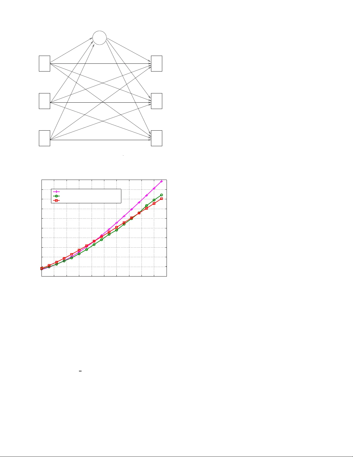
1 Approaching the Capacity of W ireless Netw orks through Distrib uted Interference Alignment Krishna Gomadam, V i veck R. Cadambe, Syed A. Jafar Electrical Engineering and Computer Scien ce Univ ersity of California, Irvine, CA 92697-2625 Email: { kgomada m, vcadambe, syed } @uci.edu Abstract — Recent results establish the optimality of interfer- ence alignment to approa ch the Shannon capacity of inter - ference networks at high SNR. Howe ver , the extent to whi ch interference can b e aligned ov er a finite number of signalling dimensions remains unknown. An other important concern f or interference alignment schemes is the requirement of global channel kn owledge. In t his work we prov ide examples of iterative algorithms that uti lize the reciprocity of wireless networks to achiev e interference alignment with only local channel kn owledge at each node. These algorithms also provide numerical insight s into the feasibi lity of i nterference alignment that are n ot yet a vailable in theory . I . I N T RO D U C T I O N The recen t emergence of the idea of interfer ence alignment for wireless networks has sho wn tha t the capacity of wireless networks can be much higher than pre viously belie ved [1]. The canonical example of inter ference alignm ent is a co mmun ica- tion scen ario where, regardless of the nu mber o f inter ferers, ev ery user is able to access one half of th e spectru m fr ee fr om interferen ce fro m other users [1]. For the interfere nce ch annel with K tran smitters and K receivers and rando m, time varying channel co efficients drawn from a co ntinuou s distribution, referenc e [1] charac terizes the network sum capacity a s C Σ ( S N R ) = K 2 log( S N R ) + o (log ( S N R )) (1) so that the cap acity per user is 1 2 log( S N R ) + o (log( S N R )) . Here SNR is d efined as the total tran smit power of all the transmitters in the network wh en the local noise power at each nod e is no rmalized to un ity . The o (log( S N R )) term, b y definition, b ecomes negligible comp ared to log( S N R ) at h igh SNR. Therefore the accuracy of the ca pacity ap proxim ation in (1) approa ches 100% at hig h SNR. Since the capacity of a single user in th e absence of all in terferenc e is log( S N R ) + o (log( S N R )) , the m ain result of [ 1] may be summ arized as: “ At high S NR, e very u ser in a wir eless interfer en ce network is (simultane ously and almost sur e ly) able to achieve (nearly) one half of the cap acity th at he could achie ve in the absence of all interfer ence. ” The capacity-o ptimal achiev able scheme within o (log( SNR )) is sho wn to be the interference alignme nt scheme. I nterferen ce a lignment on the K user inter ference channel refers to the idea of constructin g signals in such a way that they c ast overlapping shadows over one half of the signal space o bserved by each receiver wh ere they constitute interferen ce, leaving the o ther half of the signal space free of interferen ce for the d esired sign al. Th is app roach reveals the sub-optim ality of the cake-cu tting view o f spectru m a llocation between co-existing wireless systems because, essentially , ev eryone gets “h alf the cake”. Interfer ence alignment schemes ar e presented in [1 ] in the form of closed form expressions for the transmit precodin g matrices. Ho we ver , these closed form expr essions require global ch annel k nowledge wh ich can be an overwhelming overhead in practice. Mo reover , closed fo rm solutions h av e only b een fo und in certain cases. In gener al, analytical solu- tions to interfere nce alignm ent p roblem a re d ifficult to obtain and ev en the feasibility of inter ference alignm ent over a limited numbe r of signalling dimension s is an open pro blem. In this paper we explore distributed interfer ence alignment algorithm s to accomp lish the following ob jectiv es. • Req uire only local cha nnel k nowledge at each node. Specifically , each rec eiv er is assumed to know o nly the channel to its desired tr ansmitter and the covariance matrix of its effective noise (consisting of the A WGN and the interference f rom all o ther users). • Pr ovide numeric al insights into th e f easibility of align- ment. W e pro pose iterati ve algorithms that take a co gnitive ap- proach to interf erence managem ent an d utilize o nly the loc al side inform ation available naturally du e to the recip rocity o f wireless n etworks. Th e two ke y pro perties c an be sum marized as follows. • Cogn itive Prin ciple: Unlike selfish a pproac hes studied in prior work where each transmitter tries to ma ximize his own rate by transmitting along th ose signaling di- mensions where his desired receiver sees the least in- terference , we follow an un selfish app roach where each transmitter pr imarily trie s to minimize th e interferenc e to unintend ed receivers. Since avoiding in terferenc e to unintend ed receivers is th e defining feature of cog nitive radio [2] the u nselfish approac h is a cognitive appro ach. The c ognitive app roach is fou nd to lead to interfer ence alignment, an d is thus capable of approachin g n etwork capacity at h igh SNR. • R ecipr o city: For a giv en transmitter , learning how mu ch interferen ce is cau sed a t unintend ed receivers can r e- 2 quire too much side infor mation, and is one of the key challenges for co gnitive radio systems. Howe ver, this in formatio n is naturally av ailab le because o f the reciprocity of the chan nel f or networks where two-way commun ication is b ased o n tim e-division du plex opera- tion with synchronize d time -slots. Due to rec iprocity , the signalling dimensio ns along which a receiving no de sees the least interference from other users are also the same signalling d imensions alon g wh ich this nod e will cause the least in terferen ce to o ther nodes in the reciproca l network wher e all transmitters and re ceiv ers switch ro les. The paper is organized as follows. In the next section, we r evie w some o ptimization a pproac hes fo r inter ference networks in existing literature. In Section IV we state th e open proble m of deter mining the feasibility of interfer ence alignment over a limited numbe r of signaling dimen sions. The same section also describes the recipr ocity property of interferen ce align ment. In Section V we present itera ti ve interferen ce alig nment algo rithms. In Section VI, we show that th ese algorith m c an a chieve perfor mance close to th e theoretical results and discuss a few applications. W e con clude with Section VII. Notation: W e use lower case for scalars, up per case for vectors and b old fo nt to deno te matrices. A ⋆d represents th e d th column of m atrix A . I d represents th e d × d identity matrix. T r [ A ] denotes the trace of the m atrix A an d A † is the conjuga te transpose of matrix A . Fin ally , K , { 1 , 2 , · · · , K } is the index set of K users. I I . I N T E R F E R E N C E O P T I M I Z AT I O N A P P RO AC H E S The op timality of interference alignme nt schemes at high SNR is interesting becau se the se scheme s treat all interfer ence as noise and req uire no m ulti-user detection. Achiev able schemes based on treatin g interf erence as n oise have be en explored extensively over the last dec ade. Prominent among these ar e the interfere nce av o idance and iterative w aterfilling algorithm s where each transmitter acts selfishly to align its transmissions alo ng those directions wher e its desired receiver sees th e least interference [3 ]–[7] , and n etwork du ality ap - proach es [8]– [11] that are based o n the recip rocity o f the wireless propagatio n channel. A. Interference A vo idance and I terative W aterfi lling Iterative algorithms are co mmonly used for various resource allocation pro blems, such as in terferen ce avoidance and it- erative waterfilling. Howe ver , the p hilosoph y o f interf erence alignment is q uite distinct fro m both iterative waterfilling and interferen ce a voidance. W ith iterati ve waterfilling/interference av o idance algor ithms [3] , [12], [13 ], each transmitter trie s to do what is best f or his own r eceiv er , i.e., each tran smitter allocates its p ower in a manne r best suited for his desired receiver . W ith interfer ence alig nment ea ch transmitter tries to minim ize th e interf erence h e causes to other receivers. The interference align ment schemes in [1] , [1 4]–[1 6] show that for interferen ce networks, the “do no h arm” ap proach is u 3 u 1 u 2 Fig. 1. Interfere nce al ignment solu tion for the thre e user two antenna case. The arro ws in the red i ndicate th e direction of the interfere nce. much mor e powerful, an d is in fact capacity-o ptimal with in o (log( SNR )) , than the “help your self ” approach of interfer- ence a voidance and iterative waterfilling schemes. From a game- theoretic persp ectiv e, in terference a voidance and iterative waterfilling algorith ms lead to a stable op erating point co mmon ly k nown as th e Na sh eq uilibrium . At Nash equilibriu m, there is no incentive f or any u ser to un ilaterally change his transmit strategy . Often these points are not o p- timum from a network perspective and indicate inefficiency in wireless n etwork oper ation [1 7], [1 8]. Interestingly , inter- ference alignment is not a Nash eq uilibrium point if the goal of each user is to maximize his own rate. Fig. 1 sho ws th e interferen ce alignment solution for the three user two anten na case. Notice that inter fering signals are co-lin ear at each receiver while the desired s ignal may not be exactly or thogo nal to the interferen ce - a price paid for inter ference alignment. It can b e easily observed that the interference alignmen t solution is not a N ash equilibr ium po int. Fixing the transmit strategy for u sers 2 and 3, th e best strategy for u ser 1 is to cho ose u 1 such that his signal is orthog onal to the interference at receiver 1. Altho ugh this strategy is go od fo r u ser 1, it will destroy interference align ment at receivers 2 and 3. Thu s Fig. 1 clearly highlights the dif f erence between the optimal strategy of interf erence alig nment a nd the selfish strategy o f iterative waterfilling or inter ference a voidance. Iterative schemes ha ve also been used to implicitly ach iev e interferen ce alignmen t on th e 2 user X chan nel in [ 19]–[ 21]. Howe ver, for the 2 user X channel inter ference alig nment can be explicitly achieved with r oughly the same am ount of channel knowledge as requir ed by the iterative sch emes, without th e n eed for an iterativ e p rocess [ 14]. Th e itera ti ve schemes of [19] are specialized for the 2 user X c hannel an d generalizatio ns to X networks and interference networks with more than 2 u sers are n ot straightforward. B. Network Duality Another ap proach taken in pr ior work is to e xploit the dual- ity relationship s enabled by the reciprocity of the pr opagatio n channel. For example, network duality ensures that the same set of signal to interf erence and no ise ratios ( SINRs) can be achieved in th e or iginal and the reciprocal network with the 3 same total tran smit p ower [8], [9]. Network du ality is used in [9], [1 0] to minimize the total transmit power required to suppo rt a feasible rate vector . Recip rocity of propagatio n channels is used in [11] for optimal f requen cy a llocation problem . In this work we provide examples o f iter ativ e alg orithms to ach iev e interferen ce alignment o n wireless interfer ence channels. These algor ithms combine elements of all the ab ove- mentioned approach es, especially [19] and [11]. I I I . S Y S T E M M O D E L Consider th e K -user MIMO inter ference ch annel wher e the k th transmitter and receiver a re equip ped with M [ k ] and N [ k ] antennas r espectively . Note that the anten nas cou ld repr esent symbol extensio ns in time or frequ ency as well. Howev er , if the anten nas co rrespon d to symbol exten sions over orth ogona l dimensions (time, frequen cy slots) th en the ch annel m atrices will ha ve a diag onal structure. Th e channel is de fined as: Y [ k ] ( n ) = K X l =1 H [ kl ] ( n ) X [ l ] ( n ) + Z [ k ] ( n ) , ∀ k ∈ K where, at the n th channel use, Y [ k ] ( n ) , Z [ k ] ( n ) are the N [ k ] × 1 received signal vector an d the zero m ean unit variance circu - larly symmetric additive white Gaussian noise vector (A WGN) at receiver k , X [ l ] ( n ) i s the M [ l ] × 1 signal vector transm itted by transmitter l , and H [ kl ] ( n ) is th e N [ k ] × M [ l ] matrix of channel coefficients between transmitter l and recei ver k . The transmit power at transmitter l is E [ || X [ l ] || 2 ] = P [ l ] . For the K user interf erence channel defined ab ove, we also define a r eciprocal channel, where the r ole of transm itters and recei vers are switched. For e very variable on the orig inal channel, the corr espondin g v ariable on the r eciprocal ch annel is d enoted with a left arro w on top. The r eciprocal chann el is defined as: ← − Y [ k ] ( n ) = K X l =1 ← − H [ kl ] ( n ) ← − X [ l ] ( n ) + ← − Z [ k ] ( n ) , ∀ k ∈ K where, at the n th channel use, ← − Y [ k ] ( n ) , ← − Z [ k ] ( n ) are th e M [ k ] × 1 received signa l vector and the zero mean unit v ariance circularly symmetric additive white Gaussian noise vector (A WGN) at recei ver k which is equ ipped with M [ k ] antennas, ← − X [ l ] ( n ) is the N [ l ] × 1 signal vector transmitted b y tran smitter l , and ← − H [ kl ] ( n ) = H [ lk ] † ( n ) is the M [ k ] × N [ l ] matrix of channel coefficients between transmitter l and recei ver k . The transmit p owers at transmitter l on the reciprocal c hannel is E [ || ← − X [ l ] || 2 = ← − P [ l ] . The c hannel use index n is hen ceforth suppressed to a void cumbersom e no tation. I V . I N T E R F E R E N C E A L I G N M E N T OV E R L I M I T E D D I M E N S I O N S - A N O P E N P RO B L E M References [1] and [1 5] p resent interfer ence alignm ent schemes th at are co nstructed over symbo l extensions of time- varying channels. It is shown that by using long symbo l exten- sions the degrees of fr eedom achieved per dimen sion approac h arbitrarily close to the th eoretical outerb ound , thereby estab- lishing the degrees of fre edom of time-varying interferenc e and X network s. Howe ver , the extent to which interferen ce can be aligned over a limited numb er of dimension s remains an op en pro blem. As a conseq uence, the max imum num ber of degrees o f freedom tha t ca n be a chieved thro ugh align ment of interfere nce signal vectors is not kn own in general. Note that interference alignment can also be accomplished in ter ms of signal levels rather than signal vectors b y using structur ed codes (multilev el an d lattice co des) as shown in [ 22], [23]. Howe ver, in this work our focu s is o n interferen ce alig n- ment thro ugh signal vectors. W e first revie w the interfe rence alignment pro blem and th e re ciprocity pro perty of interfer ence alignment. Let d [ k ] ≤ min( M [ k ] , N [ k ] ) , k ∈ K den ote the degrees of freedom for u ser k ’ s message. Pr e coding at T ransmitter: Let V [ k ] be an M [ k ] × d [ k ] matrix whose c olumns are the orthon ormal basis of the transmitted signal spac e of user k . Mathematically , the transmitted signa l vector of user k is giv en b y: X [ k ] = d [ k ] X d =1 V [ k ] [ ⋆d ] X [ k ] d = V [ k ] X [ k ] , X [ k ] ∼ N 0 , P [ k ] d [ k ] I d [ k ] (2) Each ele ment o f the d [ k ] × 1 vector X [ k ] represents an indepen dently e ncoded Gaussian codebook symbol with power P [ k ] d [ k ] that is beamform ed with the correspon ding vector of V [ k ] . Remark: For interfer ence alignmen t or the ach iev a bility of the degrees of freedom it suffices if the beamformin g vectors are linearly indepen dent. Ho we ver , we assume the beamfor m- ing v ectors are o rthon ormal in the formulation above. Note that this does not affect th e feasibility of interferenc e alignmen t, and it naturally lead s to the iterati ve algorithm to be presented in this p aper . Interfer ence Sup pr ession at Receiver: Let U [ k ] be an N [ k ] × d [ k ] matrix whose columns are th e orthon ormal basis of the interferen ce-free desired signal subspace at recei ver k . Th e k th receiver filters its recei ved signal to obtain: Y [ k ] = U [ k ] † Y [ k ] (3) If interferen ce is aligned into the null space of U [ k ] then the following con dition mu st be satisfied: U [ k ] † H [ kj ] V [ j ] = 0 , ∀ j 6 = k (4) rank U [ k ] † H [ kk ] V [ k ] = d k (5) In other words the d esired signals are received through a d [ k ] × d [ k ] full rank channel matrix H [ kk ] , U [ k ] † H [ kk ] V [ k ] while the inter ference is comp letely eliminated . Th e ef fectiv e channel for user k is then expressed as: Y [ k ] = H [ kk ] X [ k ] + Z [ k ] (6) where Z [ k ] ∼ N (0 , I ) is the ef fectiv e d [ k ] × 1 A WGN vector 4 at receiv er k . The rate ach iev ed o n this c hannel is: R [ k ] = log I d [ k ] + P [ k ] d [ k ] H [ kk ] H [ kk ] † (7) = d [ k ] log( P [ k ] ) + o (log( P [ k ] )) (8) Thus, d [ k ] degrees of freed om a re achie ved by user k . A. F easibility of Alignment Giv en the channel m atrices H [ kj ] , k , j ∈ K , we say that the degrees of freed om allocatio n ( d [1] , d [2] , · · · , d [ K ] ) is feasible if there exist transmit preco ding matrice s V [ k ] and receive interferen ce suppre ssion matrices U [ k ] : V [ k ] : M [ k ] × d [ k ] , V [ k ] † V [ k ] = I d [ k ] (9) U [ k ] : N [ k ] × d [ k ] , U [ k ] † U [ k ] = I d [ k ] (10) such that U [ k ] † H [ kj ] V [ j ] = 0 , ∀ j 6 = k (11) rank U [ k ] † H [ kk ] V [ k ] = d k , ∀ k ∈ K (12) Remark: Sup pose all the elemen ts of the channel matrices are rand omly and ind ependen tly generated from co ntinuou s distributions and V [ k ] , U [ k ] , k ∈ K can be foun d to satisfy condition (11 ). Then, co ndition (12) will also be satisfied with probab ility 1 . This is because th e direct channel matrices H [ kk ] do not ap pear in cond ition (11). So the ch oice of transmit and receive filters V [ k ] , U [ k ] , k ∈ K to satisfy (11) d oes not depend on the dir ect chann el matrices H [ kk ] . Since H [ kk ] is indepen dent of V [ k ] , U [ k ] and all its elemen ts are rando mly generated from a c ontinuo us distribution (i.e. it lack s any special structure) , the p rodu ct m atrix U [ k ] T H [ kk ] V [ k ] has full rank with pr obability 1 . Th us, for rando m M IMO chan nels without time- extensions, if (1 1) can be satisfied then (12) is automatically satisfied almost surely as well. Howe ver , if time- extensions are con sidered then the channel matrices may have a block diagonal structure and (12) cannot b e taken for gran ted. The solution to the fea sibility p roblem is not k nown in general. In oth er word s, giv en a set of ran domly g ener- ated ch annel matrice s an d a degree-o f-freed om allo cation ( d [1] , d [2] , · · · , d [ K ] ) , it is n ot k nown if one can almost su rely find transmit an d receive filter s that will satisfy the feasibility condition s. The distributed interf erence algo rithm d ev eloped in this paper will be useful in (numer ically) solving this o pen problem . B. Recip r ocity of Alignment An interesting o bservation from the p roblem formulatio n above is the duality re lationship between in terferen ce align - ment on a gi ven interference channel and its reciprocal channel obtained by switching the dir ection of communication. Specif- ically , let ← − V [ k ] , ← − U [ k ] denote the tran smit precod ing filters and the receive inter ference suppression filters on the reciprocal channel. The feasibility cond itions o n the reciproca l cha nnel are: ← − V [ k ] : N [ k ] × d [ k ] , ← − U [ k ] † ← − U [ k ] = I d [ k ] (13) ← − U [ k ] : M [ k ] × d [ k ] , ← − U [ k ] † ← − U [ k ] = I d [ k ] (14) such that ← − U [ j ] † ← − H [ j k ] ← − V [ k ] = 0 , ∀ j 6 = k (15) rank ← − U [ k ] † ← − H [ kk ] ← − V [ k ] = d k , ∀ k ∈ K (1 6) Suppose we set ← − V [ k ] = U [ k ] , ← − U [ k ] = V [ k ] . Then th e feasibil- ity conditions o n the reciprocal channel become id entical to th e original fea sibility co nditions. T hus, the follo wing obser vation can be m ade: Reciprocity of Alignment: Since the feasibility co ndi- tions ar e identical, if the d e gr ees of freedom allo cation ( d [1] , d [2] , · · · , d [ K ] ) is fea sible on the original interference network then it is also feasible on th e r ecipr o cal netwo rk (a nd vice versa). In terfer en ce alignmen t on the recipr ocal inter- fer en ce network is simply a chieved by choo sing the transmit filters and the receive filters on th e r ecipr oca l channel as the r eceive filters and the transmit filters ( r esp ectively) of th e original channel. Reciprocity o f alignm ent is a key property used for dis- tributed in terferen ce alignme nt alg orithms, described in th e next section. V . D I S T R I B U T E D A L G O R I T H M F O R I N T E R F E R E N C E A L I G N M E N T In th is section we c onstruct distributed interf erence align- ment algorithm s fo r the interferenc e ch annel with multiple- antenna nodes and no symb ol extension s. Con tinuing with the system mo del of Section IV, this im plies that the rele- vant interferen ce alignme nt feasibility condition is (11) while (12) is automatically satisfied. Basically , (11) req uires that at each re ceiv er , all inter ference is suppressed, leaving as many interference-f ree dimen sions as the degrees of fr eedom allocated to that r eceiver . Since we are interested in d istributed alg orithms, we start with arbitrary transmit and recei ve filters V [ k ] , U [ k ] and itera- ti vely update these filters to approach interference alignment. The quality of alig nment is measure d by the power in the leak- age interference at each receiver , i.e. the interferenc e power remaining in the received signal af ter the receive interferen ce suppression filter is applied. The goal is to achieve inter ference alignment b y progressively re ducing the leakag e inter ference. If interference alignm ent is feasible the n eventually leakage interferen ce will be zero. The total interferen ce leakage at receiver k due to all undesired transmitters ( j 6 = k ) is given by: I [ k⋆ ] = Tr h U [ k ] † Q [ k ] U [ k ] i (17) where Q [ k ] = K X j =1 ,j 6 = k P [ j ] d [ j ] H [ kj ] V [ j ] V [ j ] † H [ kj ] † (18) 5 Optimize V [2] Reverse communication direction Reverse communication direction V [1] Optimize U [ K ] V [2] V [ K ] Optimize U [1] Optimize U [2] Optimize V [1] U [1] U [2] U [ K ] Optimize V [ K ] Fig. 2. Pictori al representa tion of the iterati ve int erferenc e al ignment algori thm where th e rec ei ve dire ctions are optimized to minimize inter ference power at the rec ei ve rs. Each link (a rro w) repre sents a MIMO channel . The transmit po wer per node is P in both dir ection s. is the interference covariance m atrix at recei ver k . Similarly , in the reciprocal network, the total interfer ence leakage at re ceiv er j d ue to all undesired transmitters ( k 6 = j ) is gi ven b y: ← − I [ j ⋆ ] = Tr h ← − U [ j ] † ← − Q [ j ] ← − U [ j ] i (19) where ← − Q [ j ] = K X k =1 ,k 6 = j ← − P [ k ] d [ k ] ← − H [ j k ] ← − V [ k ] ← − V [ k ] † ← − H [ j k ] † (20) is the interference covariance m atrix at recei ver j . The iterative algorithm alternates between the o riginal and reciproca l networks. W ithin each network o nly the receivers update their interf erence suppression filters to minimize their total leakage interference. Step I: In the o riginal network, each r eceiver solves the following op timization problem. min U [ k ] : N [ k ] × d [ k ] , U [ k ] U [ k ] † = I d [ k ] I [ k⋆ ] (21) In o ther words, r eceiver k chooses its interference su ppression filter U [ k ] to m inimize the leakage interferen ce du e to all undesired transmitters. The d [ k ] dimensiona l rec eiv ed signal subspace that co ntains th e least interferen ce is the space spanned by the eigenvectors corresponding to th e d [ k ] smallest eigenv alu es of the interf erence cov ariance m atrix Q [ k ] . Thus, the d [ k ] columns of U [ k ] are gi ven by: U [ k ] ⋆d = ν d [ Q [ k ] ] , d = 1 , · · · , d [ k ] (22) where ν d [ A ] is the eig en vector correspon ding to the d th smallest eigen value of A . Step II : The second step is identical to the first step, but perfor med in the recipr ocal network. Con sider th e r eciprocal network obtained by reversing the roles o f th e tran smitters and the receivers. Th e transmit p recodin g matr ices in the recip - rocal network, ← − V [ k ] , are the receive interference suppression matrices U [ k ] from the original network that were d etermined in Step I. Ea ch receiver in the recip rocal ne twork solves the following op timization pr oblem. min ← − U [ j ] : M [ j ] × d [ j ] , ← − U [ j ] ← − U [ j ] † = I d [ j ] ← − I [ j ⋆ ] (23) Similar to Step I , the d [ j ] columns of ← − U [ j ] are gi ven by: ← − U [ j ] ⋆d = ν d [ ← − Q [ j ] ] , d = 1 , · · · , d [ j ] (24) The rece iv e interference suppre ssion filters in the recip rocal network are then used as the transm it preco ding m atrices in the origin al n etwork, an d the algor ithm retu rns to Step I. The iterations co ntinue in this manner until th e algorithm conv erges. The iterative pr ocedur e is summarized in Algor ithm 1. A pictorial representation is shown in Fig. 2. A. Pr oof of Con verg ence W e now sh ow that the algorithm mu st conver ge. T he p roof also highlights the intu ition behind the algo rithm. W e define a metric called th e weighted leakag e interf erence (WLI) as: I w = K X k =1 K X j =1 ,j 6 = k ← − P [ k ] d [ k ] I [ kj ] = K X k =1 K X j =1 ,j 6 = k ← − P [ k ] d [ k ] P [ j ] d [ j ] T r h U [ k ] † H [ kj ] V [ j ] V [ j ] † H [ kj ] † U [ k ] i W e show that each step in the algorithm redu ces the value of WLI. Since WLI is bound ed below by zero, this implies 6 Algorithm 1 Itera ti ve interf erence align ment 1: Start with ar bitrary prec oding matrices V [ j ] : M [ j ] × d [ j ] , V [ j ] V [ j ] † = I d [ j ] . 2: Begin iteration 3: Compu te interference covariance matrix at the receivers: Q [ k ] = K X j =1 ,j 6 = k P [ j ] d [ j ] H [ kj ] V [ j ] V [ j ] † H [ kj ] † 4: Compu te the interference supp ression matr ix at each re- ceiv er: U [ k ] ⋆d = ν d [ Q [ k ] ] , d = 1 , · · · , d [ k ] 5: Reverse th e communication direction and set ← − V [ k ] = U [ k ] . 6: Compu te interferen ce covariance matrix at the new r e- ceiv ers: ← − Q [ j ] = K X k =1 ,k 6 = j ← − P [ k ] d [ k ] ← − H [ j k ] ← − V [ k ] ← − V [ k ] † ← − H [ j k ] † 7: Compu te the interference supp ression matr ix at each re- ceiv er: ← − U [ j ] ⋆d = ν d [ ← − Q [ j ] ] , d = 1 , · · · , d [ k ] 8: Reverse th e communication direction and set V [ k ] = ← − U [ k ] . 9: Continu e till co n vergence. that the algorith m must converge. Note that an in terference alignment solution correspond s to WLI = 0 . The WLI associated with rec eiv er k is I [ k⋆ ] w = ← − P [ k ] d [ k ] K X j =1 ,j 6 = k P [ j ] d [ j ] T r h U [ k ] † H [ kj ] V [ j ] V [ j ] † H [ kj ] † U [ k ] i = ← − P [ k ] d [ k ] T r h U [ k ] † Q [ k ] U [ k ] i = ← − P [ k ] d [ k ] I [ k⋆ ] Therefo re the value of U [ k ] computed in Step 4 to m inimize I [ k⋆ ] also minimizes I [ k⋆ ] w . Since I w = P K k =1 I [ k⋆ ] w , we ha ve min U [1] , U [2] , ··· , U [ K ] I w = min U [1] , U [2] , ··· , U [ K ] K X k =1 I [ k⋆ ] w = K X k =1 min U [ k ] I [ k⋆ ] w = K X k =1 ← − P [ k ] d [ k ] min U [ k ] I [ k⋆ ] In other words, given the values of V [ j ] , j ∈ { 1 , 2 , · · · , K } , Step 4 minimizes the value of I w over all possible ch oices of U [ k ] , k ∈ { 1 , 2 , · · · , K } . In particular, Step 4 can only reduce the value of I w . The weighted leakag e in terferenc e associated with tra nsmit- ter j is I [ ⋆j ] w = P [ j ] d [ j ] K X k =1 ← − P [ k ] d [ k ] T r h U [ k ] † H [ kj ] V [ j ] V [ j ] † H [ kj ] † U [ k ] i = P [ j ] d [ j ] K X k =1 ← − P [ k ] d [ k ] T r h ← − V [ k ] † ← − H [ j k ] † ← − U [ j ] ← − U [ j ] † ← − H [ j k ] ← − V [ k ] i = P [ j ] d [ j ] K X k =1 ← − P [ k ] d [ k ] T r h ← − U [ j ] † ← − H [ j k ] ← − V [ k ] ← − V [ k ] † ← − H [ j k ] † ← − U [ j ] i = P [ j ] d [ j ] T r h ← − U [ j ] † ← − Q [ j ] ← − U [ j ] i Therefo re the value of ← − U [ j ] computed in Step 7 to minimize ← − I [ j ⋆ ] also min imizes I [ ⋆j ] w . Since I w = P K k =1 I [ ⋆j ] w , it is e asily seen that Step 7 c an also only red uce the value of I w . Since the v alue o f I w is monoton ically redu ced after e very iteratio n, conv ergence of th e algorithm is g uaranteed . Remark: While the algorithm minimizes leakage interfer- ence at ev ery iteration an d is g uarante ed to conver ge, co n- vergence to glob al minimu m is not guarante ed du e to the non-co n vex nature o f the in terferen ce op timization problem . Numerical results for the p erfor mance of the algorithm are presented in the n ext section . The f ollowing observations summarize the intuition behind the iterati ve algo rithm. 1) Dimen sions along which a re ceiv er sees the least in ter- ference from other nodes are also th e dim ensions alo ng which it causes th e least interf erence to other nod es in the r eciprocal n etwork wher e it fun ctions as a tr ansmitter . 2) Th e weig hted leakage interference is un change d in the original and reciproc al networks if the transmit and receive filters are switched. B. Max-S INR Alg orithm The algo rithm pr esented above seeks perfect inter ference alignment. In particular it seeks to cr eate an interference - free subspace o f the r equired nu mber of dimen sions, that is design ated as the d esir ed sign al sub space. Howe ver , no te that interfe rence alig nment makes no attempt to max imize the desired signal power within the desired signal sub space. In fact the algorithm described above d oes n ot dep end at all on the d irect chan nels H [ kk ] throug h which the desired signal arrives at the intend ed receiver . Th erefor e, while th e interferen ce is eliminated within the desired space, no coherent combinin g gain (arr ay gain) for the desired signal is obtained with inter ference alignme nt. While this is optimal as all signal powers appr oach infinity , it is not op timal in general at intermedia te SNR values. Ther efore o ther algorithm s may be design ed which will perf orm better than the interferenc e alignment algorithm at in termediate SNR values. In this sectio n we conside r one such n atural extension of the interferen ce alignment algorithm where the receive filters U [ k ] and ← − U [ k ] are chosen to max imize SINR a t th e receivers instead of only minimizing the leakage interferen ce. While there is no loss of gener ality in assuming orthog onal precoding vectors for the strea ms sent from the same tr ansmitter as far as interf erence alignment is concern ed, orthogo nal precoding vectors are in general suboptimal for SINR optimizatio n. W e therefor e no longer assume that the column s o f V [ k ] (the transmit precoding vectors) are mutually o rthog onal. W e also identify the column s o f U [ k ] to b e the specific c ombinin g vectors fo r th e co rrespon ding desired data stream, so that 7 they are not ne cessarily ortho gonal either . W ith these mod ified definitions, the SINR o f the l th stream of the k th receiver is SINR kl = U [ k ] † ⋆l H [ kk ] V [ k ] ⋆l V [ k ] † ⋆l H [ kk ] † U [ k ] ⋆l U [ k ] † ⋆l B [ kl ] U [ k ] ⋆l P [ k ] d [ k ] (25) where B [ kl ] = K X j =1 P [ j ] d [ j ] d [ j ] X d =1 H [ kj ] V [ j ] ⋆d V [ j ] † ⋆d H [ kj ] † − P [ k ] d [ k ] H [ kk ] V [ k ] ⋆l V [ k ] † ⋆l H [ kk ] † + I N [ k ] (26) The unit vector U [ k ] ⋆l that maximizes SINR kl is giv en b y U [ k ] ⋆l = B [ kl ] − 1 H [ kk ] V [ k ] ⋆l k B [ kl ] − 1 H [ kk ] V [ k ] ⋆l k . (27) The steps of the iteratio n are g iv en in Algo rithm 2. Algorithm 2 Max -SINR algorithm 1: Start with any V [ k ] : M [ k ] × d [ k ] , co lumns of V [ k ] are linearly independ ent unit vectors. 2: Begin iteration 3: Compu te interfer ence plus noise covariance matrix fo r B [ kl ] for stream l at receiver k ac cording to (26), ∀ k ∈ { 1 , 2 , · · · , K } , l ∈ { 1 , 2 , · · · , d [ k ] } . 4: Calculate recei ve combining vectors U [ k ] ⋆l at receiver k ac- cording to (27), ∀ k ∈ { 1 , 2 , · · · , K } , l ∈ { 1 , 2 , · · · , d [ k ] } . 5: Reverse the commu nication d irection and use the recei ve combinin g vectors as pr ecoding vectors: ← − V [ k ] = U [ k ] , ∀ k ∈ { 1 , 2 , · · · , K } . 6: In th e r eciprocal network, com pute interfer ence plus-no ise covariance matrix ← − B [ kl ] for stream l at recei ver k , ∀ k ∈ { 1 , 2 , · · · , K } , l ∈ { 1 , 2 , · · · , d [ k ] } . 7: Calculate receive combinin g vectors ← − U [ k ] ⋆l , ∀ k ∈ { 1 , 2 , · · · , K } , l ∈ { 1 , 2 , · · · , d [ k ] } . 8: Reverse the commu nication d irection and use the recei ve combinin g vectors as pr ecoding vectors: V [ k ] = ← − U [ k ] , ∀ k ∈ { 1 , 2 , · · · , K } . 9: Repeat until conv ergence. V I . P E R F O R M A N C E R E S U LT S A N D A P P L I C A T I O N S Consider the 3 user inter ference chan nel where each node is equipp ed with 2 antennas and all channel coefficients are i.i.d. zero mean unit variance circularly symmetric comp lex Gaussian. As shown in Fig. 1 with in terferen ce alignment each user achie ves 1 degree of fr eedom. I n Fig. 3 we compar e the perfor mance of the iterativ e interference alignmen t algorithm for this ch annel with th e theor etical in terference alignm ent which assumes global ch annel knowledge. It can be seen that the algorithm perfor ms very close to the theor etical case and more importantly it provid es significan t b enefits over the orthog onal case. The sum rate for the orthog onal schem e is calculated assuming eq ual time sharing f or the users, and with po wer 3 P per nod e. T he mo dified in terferen ce alignme nt 0 5 10 15 20 25 30 35 40 0 5 10 15 20 25 30 35 40 User power in dB Average sum rate in bits per use Max−SINR algorithm Interference alignment (Centralized) Interference alignment (Decentralized) Orthogonal Single user 2x2 Interference avoidance Isotropic transmission Fig. 3. Performance of the dec entral ized interfere nce ali gnment algor ithm for the three user two antenna case. scheme wh ere the receive-combining vectors m aximize the SINR provides a considerab le perf orman ce gain at low an d intermediate P . As expected, it achiev es t he same perform ance of interferen ce alig nment at high P . W e also plot the perfor- mance of in terferenc e a voidance algorithm which is a selfish approa ch. T he isotro pic transmission ca se refers to the case where each transmitter sends 2 streams of equa l power without regard to the channel information. In the following, we explore some of th e ap plications of the iterative interference alignm ent algorithm . A. F easibility of I nterfer ence Alignment While the iterative algor ithm is useful for circumventing the n eed fo r glo bal channel knowledge, it can also be used to ch eck th eoretical feasibility of interferen ce alignment for a giv en num ber of streams per user . L et ( d [1] , d [2] , · · · d [ k ] ) denote the num ber of transmit streams o f the users. For perfec t interferen ce alignment P d [ k ] j =1 λ j [ Q [ k ] ] = 0 at receiver k where λ j [ A ] d enotes the j th smallest eigenvalue of A . No te th at P d [ k ] j =1 λ j [ Q [ k ] ] indicates the interfe rence power in the desired signal space. Using the algo rithm, we plot in Fig . 4, the perc entage of interferen ce in the desired signal space versus the total nu mber of transmit streams in the network. The fraction of interference in the desired sig nal space of r eceiv er k is defined as p k = P d [ k ] j =1 λ j [ Q [ k ] ] T r [ Q [ k ] ] . (28) When interf erence alignment is feasible the fractio n of inter- ference in desired sign al space will be zero (within numerical errors). Fig . 4 suggests that interferen ce alignm ent is feasible on the four user interferen ce chan nel with 5 anten nas at each node when ea ch transmitter sen ds two stream s. With increase in the num ber of streams the interferen ce in desired 8 6 7 8 9 10 11 12 0 5 10 15 20 25 30 35 Total number of beams in network Percentage of interference in desired signal space 4 users, 4 antennas 4 users, 5 antennas Fig. 4. Percentag e of interfere nce po wer in desired signal space as a function of the to tal number of data streams in the networ k. signal space increases which is an in dication that interference alignment is not possible. Althou gh the up perbo und on the degrees o f freedom f or this n etwork is 10, appro aching the upperb ound may entail channel extension s. The plot suggests that 8 degrees of fr eedom ( d [1] = d [2] = d [3] = d [4] = 2 ) can be achieved without chan nel extension. Similarly for th e 4 antenn a case, the plot indicates th at interfer ence alignment is possible for up to a total of 6 streams in the 4 u ser interfer ence network with o nly 4 antennas at each node. B. Networks with single antenna nodes MIMO nodes are not n ecessary in o rder to ac hieve inter- ference alignment in wireless network s. Interf erence can be aligned even in networks with single an tenna no des thr ough channel extension in frequency or time as lon g as the channel is varying acro ss freque ncy or time [1]. Howe ver, one caveat with this a pproac h is the need fo r long sym bol extensions. Aligning interference with a large number of b eams over a large numb er of dimensio ns can be especially c hallenging for iterativ e algorith ms due to large dimension ality of the optimization space and th e inherently non- conv ex natur e of the problem . Mo reover , symbol extensions over o rthogo nal dimensions pro duce structur ed (diagon al o r block diagon al) matrices for which both co ndition s (12) and (11) are non- trivial. Due to these d ifficulties, it is p referred if inter ference alignment c an b e acco mplished without sy mbol extension s or with limited symbol e xtensions. In this section , we give an example o f how long symbo l extensions may be a voided by th e use of relays. Note that [16] has sho wn that relays cann ot increase the degrees of freedo m for time- varying wireless network s. Howe ver , as we show in this section, relays can be very useful b y re ducing the size of the signalling space over which interference alig nment can be accomplished . The key idea is to employ relay s to create a virtual MIMO system. Consider an interference relay channel with three sour ces, three destinations and a h alf-dup lex relay (node 0 ) as shown in Fig. 5. Recall that in the absence of relays this network is shown to approa ch the up perbo und of 3 / 2 degrees of fr eedom per orthogo nal dimen sion in the asymptotic limit o f infinitely lo ng symb ol extensions [ 1]. Howe ver, we show that with re lays o nly a two time slots are requ ired to achiev e the outerb ound , i.e. 3 / 2 degrees o f freedom . Consider the fo llowing two slot p rotoco l. In the first slot, the re lay is silent and the r eceiv ed signal at destination j is giv en b y y [ j ] (1) = 3 X i =1 h [ j i ] (1) x [ i ] (1) + z [ j ] (1) , j = 1 , 2 , 3 The receiv ed sign al at the relay can be expressed as y [0] (1) = 3 X i =1 h [0 i ] (1) x [ i ] (1) + z [0] (1) In th e second slot, the relay tr ansmits a scaled version of its received symbol wh ile so urce i transmits x [ i ] (2) . The recei ved signal at the j th destination no de in the second slot ( j = 1 , 2 , 3 ) y [ j ] (2) = 3 X i =1 h [ j i ] (2) X [ i ] (2) + h [ j 0] (2) β y [0] (1) + z [ j ] (2) Let Y [ j ] = [ y [ j ] (1) y [ j ] (2)] T and X [ i ] = [ x [ i ] (1) x [ i ] (2)] T . In vector form, the received signal at destination j can be expressed as Y [ j ] = 3 X i =1 H [ j i ] X [ i ] + Z [ j ] (29) where H [ j i ] = h [ j i ] (1) 0 β h [ j 0] (2) h [0 i ] (1) h [ j i ] (2) and Z [ j ] = z [ j ] (1) β h j 0 (2) z [0] (1) + z [ j ] (2) Thus, over two time slo ts, th e re lay n etwork redu ces to a three user MIMO interfer ence chann el with (n on-d iagonal) structure o n th e channe l matrix. Since the chann el matrix is non -diagon al (unlike symbol extensions in th e absence of a r elay) it is easy to verify th at when the channels are random and indepen dent of each other, a multiplexing g ain of 3 2 is ac hieved with pr obability 1 . The ad vantage of this scheme is that it requ ires only two time-slots to ach iev e 3 / 2 degrees of freedom per time-slot, whereas in the a bsence of the relay , infinitely many time-slots are u sed in [1] . Sin ce fewer dimensions a re nee ded, itera ti ve algo rithms work better (faster conv ergence) in this setting. In Fig . 6 we plot the perf ormance of th e interfere nce alignment schemes for th e ca se of time extensions. For the interferen ce align ment scheme with relay , the transmit po wer per node is P . That is, the three transm itters and the relay have a total power of 4 P . The tr ansmit p ower for the o rthogo nal scheme where only transm itter is acti ve at a time is 4 P . The interfere nce a lignment scheme withou t relay achieves a 9 R S2 S3 D1 D2 D3 S1 Fig. 5. Interferenc e relay channel 0 5 10 15 20 25 30 35 40 45 50 0 2 4 6 8 10 12 14 16 18 20 User power in dB Average rate in bits per use Interference alignment with relay Interference alignment (No relay) Orthogonal Fig. 6. Performance of the interf erence ali gnment schemes with time slot ext ension for the three user inte rference cha nnel. multiplexing gain of 4 in 3 time slots [1]. Her e transmitter 1 sends two streams while tr ansmitters 2 and 3 send one stream each. T he tran smit power pe r stream is P adding u p to 4 P for the scheme. W e can also increase th e number o f time slots for channel extensio n to impr ove the multiplexing gain. Howe ver it r equires very h igh P to outperform the orthogona l sch eme. It can b e seen that add ing an extra r elay h elps in achie ving th e multiplexing gain of 3 2 in two slots. Further the per forman ce improves at low P as well. It must be s tressed that the main idea behind the interference alignment sche me with the relay is to show that the re are ben- efits in emp loying relays when the nodes do not have m ultiple antennas, especially fo r iterative alg orithms. The schem e can be f urther improved by op timally alloca ting power to the relay and employin g Algor ithm 2 to improve its p erform ance at lo w P . V I I . C O N C L U S I O N Distributed in terference alignm ent algorithm s are in vesti- gated. Interference alignment is found to be achie vable thro ugh iterativ e algorith ms b ased on n etwork recipr ocity a nd the ”minimize interfer ence to o thers” appro ach. Numerica l com - parisons to orthogo nal schemes, simu ltaneous transmission schemes an d selfish inte rference avoidance sche mes sho w th at the benefits of distributed inter ference alignmen t algor ithm are sign ificant and close to the theo retical predictio ns. As mitigating in terferenc e is th e fun damen tal proble m of wireless networks, th e ’ do no harm’ appr oach based algor ithms h av e enormo us application s in wireless networks. R E F E R E N C E S [1] V . R. Cadambe and S. A. Jafar , “Inter ference alignmen t and degrees of freedom regi on for the k user int erferen ce chan nel, ” arxiv .org , 2007. arxi v eprint = cs/070 7.0323. [2] S. Srini v asa and S. J afar , “The throughput potential of cogniti ve radi o - a theoreti cal perspect i ve, ” IEEE Communicati ons Magazi ne , vol. 45, no. 5, 2007. [3] C. Rose, S. Ulukus, R. Y ate s, “Wi reless systems and interferenc e av oidanc e, ” IE EE T ransactio ns on W ire less Communicati ons , vol . 1, pp. 415–428, July 2002. [4] O. Pope scu, C. Rose, D. C. Popescu, “Signal space part itionin g versus simultane ous water filling for mutually interfer ing systems, ” in IEEE Global T elecommuni cation s Conf er ence (GLOBECOM) , No v 2004. [5] R. Menon, A. MacKenz ie, R. Buehrer , J. Reed, “Game theory and inter- ference avoid ance in dec entral ized networks, ” in SDR F orum T echni cal Confer ence , Nov 2004. [6] J. Hicks, A. Mac Ke nzie, J. Neel, J. Reed, “ A game theory perspecti ve on interference a voi dance, ” in IEE E Global T elecommuni cations Con- fer ence (GLOBECOM) , No v 2004. [7] S. Ulukus, R.D. Y ate s, “Ite rati ve construct ion of optimum signature sequence sets in synchronous cdma systems, ” IEEE T ransac tions on Informatio n Theory , vol. 47, no. 5, pp. 1989–1998, July 2001. [8] D. T se and P . V iswanath, Fundamentals of W ir eless Communication . Cambridge Univ ersity Press, 2005. [9] F . Rashid-F arrokhi, K.J.R. Liu and L. T assiulas, “Transmit beamforming and powe r contr ol for cellula r wireless systems, ” Selec ted Areas in Communicat ions, IEEE Jou rnal on , vo l. 16, no. 8, pp. 1437–1450, Oct 1998. [10] B. Song, R. Cruz and B. Rao, “Network dualit y and its applic ation to multi-user mimo wireless net works with sinr constrai nts, ” Communic a- tions, 2005. ICC 2005. 2005 IEEE Inte rnational Confere nce on , vol. 4, pp. 2684–2689 V ol. 4, 16-20 May 2005. [11] B. Babadi and V . T arokh, “ A distribute d dyn amic freque ncy alloc ation algorit hm for ad hoc networks, ” in http://arxiv .org/ab s/0711.3247 , 2007. [12] W . Y u, W . Rhee, S. Boyd, and J. M. Ciof fi, “Iterati ve water -fillin g for gaussian vector multiple-ac cess channels, ” IEEE T ransact ions on Informatio n Theory , vol. 5, no. 1, p. 145152, Jan 2005. [13] R. Etkin, A. Pare kh, and D. Tse, “Spectrum sharing for unlice nsed bands, ” Selected Areas in Communic ations, IE EE J ournal on , vol. 25, no. 3, pp. 517–528, April 2007. [14] S. Jafa r and S. Shamai, “Deg rees of free dom re gion for the mimo X channe l, ” IE EE T rans. on Information Theory , vol. 54, pp. 151–170, Jan. 2008. [15] V . R. Cadambe and S. A. J afar , “Deg rees of freedo m of wireless x netw orks, ” arxiv .org , 2007. arxiv eprint = cs/0711.282 4. [16] V . R. Cadambe and S. A. Jafar , “Can feedback, cooperat ion, relays and full duplex ope ration in crease th e degrees of free dom of wireless netw orks ?, ” January 2007. Preprint a v aila ble on author’ s website. [17] E. G. Larsson and E. A. Jorswie ck, “The MISO Interferen ce Cha nnel: Competit ion versus Collabora tion, ” in Allerton Conferen ce on Commu- nicati on, Contr ol, and Computing , Sep 2007 . [18] A. Leshem and E. Z ehav i, “Coo perati ve game theory and the gaussi an interfe rence chan nel, ” http:// arxiv .org/abs/0708 .0846 , 200 7. [19] M. Maddah-Ali, A. Motahari, and A. K handani , “Signa ling ov er MIMO mult i-base systems - combi nation of m ulti-a ccess and broadca st schemes, ” in Pr oc. of ISIT , pp. 2104–2108, 2006. 10 [20] M. Maddah -Ali, A. Motahari, and A. Khandani, “Communic ation o ver X chann el: Signall ing and multiple xing gain, ” in T ech. Report. UW -ECE- 2006-12, Universit y of W aterloo , July 2006. [21] M. Maddah -Ali, A. Motahari, and A. Khandani, “Communic ation o ver X channel: Signali ng and performance analysi s, ” in T ech. R eport. UW- ECE-2006-27, University of W aterloo , December 2006. [22] G. Bresler , A. Parek h, and D. T se, “ Approximate capacit y of the man y- to-one interferenc e channel , ” Sep. 2007. Allerton Conference. [23] V . Cadambe, S. Jafar , and S. Shamai, “Interfere nce align ment on the deterministic channel and applic ation to gaussian networks, ” arxi v:0711.2547.
Original Paper
Loading high-quality paper...
Comments & Academic Discussion
Loading comments...
Leave a Comment