Wireless MIMO Switching with Zero-forcing Relaying and Network-coded Relaying
A wireless relay with multiple antennas is called a multiple-input-multiple-output (MIMO) switch if it maps its input links to its output links using "precode-and-forward." Namely, the MIMO switch precodes the received signal vector in the uplink usi…
Authors: Fanggang Wang, Soung Chang Liew, Dongning Guo
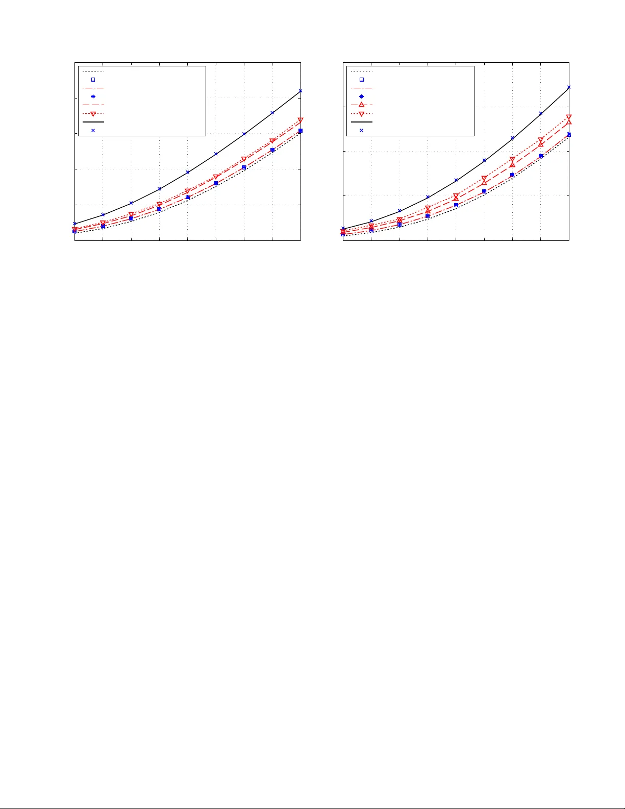
W ireless MIMO Switching with Zero-forcing Relaying and Netw ork-coded Relaying Fanggang W ang, Memb er , IEEE , Soung Chang Liew , F e llow , IEEE , and Do ngning Guo, S enior Memb er , IEEE Abstract — A wireless relay with multiple anten nas is called a multiple-input- multiple-outp ut (MIMO) switch if it maps its input links to its o utput lin ks using “precode-and-f orward. ” Namely , the MIMO switch precodes th e receive d signal ve ctor in the uplink using some matrix for transmission in the downlink. This paper studies the scenario of K stations and a MIMO switch, which has fu ll ch annel state information. Th e precoder at the MIMO switch is either a zero-f orcing matrix or a network- coded matrix. With the zero -for cin g precoder , each desti nation station receiv es only its desired signal with enhanced noise but no interference. With the network-coded precoder , each station re- ceiv es not only its desired si gnal and noise, but possibly also self- interference, which can be perfectly canceled. Pre coder design for optimizing the receiv ed signal-to-noise ratios at the destinations is inv estigated. For zero-f orcing relaying, the problem is solved in closed f orm in the two-user case, where as in the case of mo re users, efficient algorithms are proposed and shown to b e close to what can be achieved by extensiv e random search. Fo r network- coded relaying, we present efficient iterative algorithms th at can boost the throughput fu rther . Index T erms —Beamf orming, MIMO switch ing, network cod- ing, re lay , zero-f orcing. I . I N T RO D U C T I O N Relays in wireless networks can extend coverage as well as impr ove energy efficiency [ 1]. In this paper, we study a setup in which multiple single- antenna stations commu nicate with e ach other via a mu lti-antenna r elay . In each uplink slot, the stations simultan eously transmit, then in the sub sequent downlink slot, the relay precodes its rece iv ed signa l by a cer- tain matrix befo re br oadcasting to the statio ns. I n the absence of noise, the multiple-inp ut multiple-o utput (MIMO) system between th e transmitters and the re ceiv ers can be v iewed as a produ ct of the downlink chann el matrix, the precoder and th e uplink channel m atrix. I n this work , we design a zer o-forc ing precod er s o that the prod uct channel is a desired permutation matrix, whic h forms a on e-to-on e mappin g (or links) from Manuscript recei ved August 13, 2011; re vised December 21, 2011; acc epted May 5, 2012. T his work was partial ly supported by grants from the Uni v . Grants Committee of the Hong Kong , China (AoE/E-02/08; 414911); the State Key L ab of Rail T raf fic Cont rol and Safet y (RCS2011ZT011); the Fundamenta l Researc h Funds for the Cent ral Uni versities (2011JBM203 ); Program for Changjian g Scholars and Innov ativ e Research T eam in Univ . (IR T0949); the Joint Funds of Stat e Ke y Program of NSFC (60830001). F . W ang is with the State Ke y Lab of Rail Traf fic Control and Safety , School of Electronic a nd Info rmation Engineering, Beijing Jiaot ong Uni ver- sity , B eijing, Chi na, and Institute of Network C oding, The Chinese Uni versity of Hong Kong, HK SAR, Chin a (e-mail: fgw ang@inc.cu hk.edu.hk). S. Lie w is with the Department of Infor mation Engineer ing, the Chinese Uni versi ty of Hong K ong, HK SAR, Chin a (e-mail: soung@i e.cuhk.edu.hk). D. Guo is with the Department of Electrica l E ngineeri ng & Com- puter Science , Northweste rn Uni versity , Eva nston, IL, USA (e-mail: dGuo@northwe stern.edu). the transmitters to th e receivers. He nce the techniq ue is called MIMO switching. W e also study a g eneralization referred to as network-cod ed precoding where the off-diagonal elemen ts of the channel matrix form a permutation, and where the diagonal elements can b e non zero. Such n onzero diagon al elements cause s elf-inter ference, which can be fully canceled assuming the interferen ce gain s are a vailable at the receivers. W e stu dy how to design the precode r to maxim ize th e signal-to-noise ratios (SNRs) of the links. T o the best of our k nowledge, this work is the first to treat unic ast non- pairwise switching pattern s. Prior work that in vestigate data exchang e via a re lay includ es [1]–[6]. Refer- ences [2], [4], [5] in vestigate the case of “full data exchan ge, ” in which all stations want to broadcast their data to all the other stations. A slotted system with a single-a ntenna relay is considered in [ 2] and the maximum throughp ut region is ev alua ted. Data tr ansmissions in [4], [5] ca n be summar ized as follows: In the first slot, all stations transmit to the re lay simultaneou sly; subsequen t slots are dev o ted to downlink transmissions; in e ach downlink slot, the relay multiplies the signal received in the first time slot b y a different precod er , such that at the en d of all downlink slots, all stations receive the bro adcast d ata from all the o ther station s. By contrast, the framework inv estigated in this paper focuses on the u nicast case, in which station i tran smits to another station j only . (Station j may transmit to a different station than i .) Any general tran smission pattern (unica st, multicast, b roadcast, or a mixture of them ) amo ng the stations can be realized by scheduling a set o f d ifferent unicast tr ansmissions, as has b een pointed out by the authors in preliminary work [7]. A sing le- antenna relay with dif fer ent forwarding strategies is con sidered in [1], wh ich studies both f ull data exchan ge and “pairwise data exchan ge, ” in which stations for m pairs to exchange data with each other only . It is a special case of u nicast switching studied here. Reference [6] studies pairwise data exchange only , where the relay adopts the decod e-and- forward strategy . The di versity-multiplexing tradeoff under recipro cal and non- reciproca l channels is also analyze d. In this paper, we co nsider bo th pairwise an d non -pairwise switching, in which a m ulti-antenn a relay works in pr ecode- and-fo rward manner . W e first study switching traf fic among the stations using a ze ro-fo rcing MIM O r elay , where each destination receives th e desired signal with enhan ced noise. W e then s tudy a more gen eral network -coded relayin g, wh ich exploits physical-lay er network coding for p erform ance im- provement [8]–[1 1]. For fairness, we stud y how to design the precod er to maximize the minimum rec eiv ed SNR amon g all stations, which is referred to as th e ma xmin pr oblem . Since the Relay 1 2 3 K N Uplink sy mbol interv al Do wnlink sym bol interv al Fig. 1. Wirel ess MIMO switchi ng. maxmin pr oblem is NP-h ard, we use a semidefinite relaxation technique to co mpute an a pprox imate solution. Th e p roblem further simplifies if th e SNRs at all d estinations are requ ired to be iden tical, and we call it th e equ al-SNR pr oblem . W e de riv e condition s under which the max min and equal-SNR problem s are equiv alent. By ev a luating the throug hput performances of the two problems, we show the gap be tween them is small especially in the hig h SNR r egime. That is, our n umerical results suggest that we can use the equ al-SNR pr oblem to approx imate the ( NP-hard) max min pr oblem. Fu rthermo re, we show that network-coded relay ing can noticeably improve th e throug hput performance over zero -forcin g relay ing. The remainder of the paper is organized as follo ws: Sec tion II in troduce s the sch eme o f wir eless MI MO switchin g. In Section III (resp . Section IV), the max min (resp. equal-SNR) problem is in vestigated f or b oth zero-for cing and network- coded relaying. Section V p resents the simulation re sults. Section VI co ncludes this paper . I I . S Y S T E M D E S C R I P T I O N Consider K stations, number ed 1 , . . . , K , each with one antenna, as shown in Fig. 1. Ther e is no direct link betwe en any two station s an d th e stations comm unicate via a relay with N antennas. T he p recode- and-fo rward schem e app lies under the co ndition o f K ≤ N , whe re the relay has enou gh degrees of freed om to switch all d ata streams at th e same time. W e assume K = N th rough out for simplicity . In the case of K < N , a ll the ma trix in verses in the paper s hall be replaced by Moore- Penrose pseudo in verses [12]. Each transmission consists of on e uplink symbo l interval and o ne downlink symbol interval o f equal dura tion. In particular , t he tw o symbol intervals are two slots in a time-division system. T he u plink symbol interval is for simultaneous uplin k transmissions f rom the statio ns to the relay ; the downlink symbol interval is for downlink transmissions from the r elay to the stations. Each ro und o f u plink an d downlink transmission realizes a switching perm utation, as shall be described shor tly . Consider one tra nsmission. Let x = [ x 1 , · · · , x N ] T be the vector repre senting the signa ls tr ansmitted by the station s. Let y = [ y 1 , · · · , y N ] T be the received signals at the relay , and u = [ u 1 , · · · , u N ] T be th e noise vector with indepen- dent iden tically distributed (i.i.d.) n oise sam ples following circularly- symmetric complex Gaussian (CSCG) distribution, i.e., u n ∼ N c (0 , γ 2 ) . Then y = H x + u , (1) where H is th e uplin k channel gain m atrix. The relay multi- plies y by a prec oding matr ix G befo re relaying the signals. In th is p aper, we assume that the up link c hannel an d d ownlink channel a re re ciprocal, so that the downlink ch annel is H T . Thus, the received signals at the stations in vecto r form are r = H T Gy + w (2) = H T GH x + H T Gu + w , (3) where w is th e noise vector a t the r eceiver , with the i.i.d . noise samples following CSCG distribution, i.e., w n ∼ N c (0 , σ 2 ) . In the fo llowing, we describe two precodin g schemes. A. Zer o-forcing R elaying W e refer to a n N × N m atrix P that has one an d only one nonzero element on each r ow and each column , which is equal to 1 , as a permutation matrix. Evidently , P x is a column vector con sisting of the same elements as x but permute d in a certain or der dependin g on P . For example, if P = 0 0 1 1 0 0 0 1 0 , then P [ x 1 , x 2 , x 3 ] T = [ x 3 , x 1 , x 2 ] T . In the case wher e all di- agonal elements of P are zero it is also called a derangement . Suppose that the purpo se of G is to realize a p articular permutatio n rep resented by the permutatio n matrix P , and to amplify the signa ls coming from the stations. That is, H T GH = AP , (4) where A = diag { a 1 , · · · , a N } is an “amplification ” diago nal matrix. Each diagonal element is regarded as the gain of a link. Accord ingly , the precoder can be calculated as G = H − T AP H − 1 . (5) Let the receivers comp ensate f or the amplificatio n to y ield received sign als expressed collectiv ely as: ˆ r = A − 1 r = P x + v , (6) where the post-p r ocessing noise is exp ressed as v = P H − 1 u + A − 1 w . (7) Let us define Q , I + γ 2 P H − 1 H − H P T . (8) 1 2 3 1 2 3 MIMO switch a b b c c a Fig. 2. A traf fic demand among three stations. The covariance o f the post-p rocessing noise v is written as E { v v H } = γ 2 P H − 1 H − H P T + σ 2 A − 1 A − H (9) = Q − I + σ 2 A − 1 A − H . (10) Suppose all uplink tran smissions are ind ependen t and use unit av erage power , i.e., E { x 2 i } = 1 , i = 1 , · · · , N . The problem is to design the pr ecoder G to minimize the variance of the post-pr ocessing noise subject to a power constraint for the relay : E { y H G H Gy } ≤ p . (11) For notatio nal convenience, let the entries of an N × N matrix S be given by s ij , Q j i [( H ∗ ) − 1 H − T ] ij . (12) From (1), th e relay’ s transmit p ower can be ev aluated as E [ x H H H G H GH x + u H G H Gu ] = T r [ GH H H G H + γ 2 GG H ] (13) = T r [ H − T A ( I + γ 2 P H − 1 H − H P T ) A H ( H ∗ ) − 1 ] (14) = T r [ AQA H ( H ∗ ) − 1 H − T ] (15) = a H S a , (16) where we h av e used ( 5) and (8), an d a = [ a 1 , · · · , a N ] T is the gain vector with the d iagonal elements of A . The power constraint on th e relay is thu s expressed as a H S a ≤ p. (17 ) B. Network-coded Relaying The MIM O switch described in Section I I.A makes u se of zero-fo rcing relaying, by which data are switched based on a permutatio n matrix , whose d iagonal elemen ts are all zero. I f the k th diag onal element is no nzero, it means that the relay forwards the signal fr om station k bac k to itself. Th ere is no need to force a diagonal ele ment to zero be cause the self- interferen ce is known and can be removed. This is the basic idea beh ind phy sical-layer network codin g (PNC) [11], which underlies many other works, e.g., [1 3]–[16]. In gen eral, allowing PNC impr oves the perfor mance. Even though the self-in terferen ce costs the relay some en ergy , removing the co nstraint on th e diago nal of the derangemen t enlarges the possible set of th e optimizatio n problem, and thereby y ields a better optimal objective. This can also be seen fr om an example o f multi-way r elaying, in wh ich three single-anten na stations communicate with the help of a three- antenna rela y . Th e traffic switching pattern amon g the th ree y ( ) z ( κ ) x ( ı ) b ′ = b κ b ′′ = b + b κ ˜ a ˜ b ˜ c Fig. 3. Assume the channel outputs of three users’ signal vecto rs: the back vec tor ˜ b is the desi red signal; the red vector ˜ a is the self-interfere nce; the blue vector ˜ c is the other interfer ence signal. stations ar e d efined in Fig. 2. The desired signal o f station 1 is the bla ck signal b ; th e red signal a is its self-interf erence; the blue sign al c is the other interf erence sig nal. W e assume the thr ee sign als an d th e channel gain s are real-valued for simpler illustration. A sketch of the th ree signals after passing throug h th e channel is shown in Fig . 3, i.e., ˜ a , ˜ b and ˜ c , which are all three-d imensional vectors due to th ree anten nas at the relay . As shown in Fig. 3, we assume that ˜ c is along x -ax is; ˜ a is in xy -plane; and ˜ b = b ı + b + b κ . I n the ca se of zer o- forcing , the desired signal of station 1 , ˜ b , should be projected to z -axis, whic h is perpend icular to xy -p lane span ned by the two signals ˜ a and ˜ c . In this way both the two interfere nce signals are zero ed o ut and we get a p ost-pro cessing signal b ′ = b κ . Howe ver , with network co ding, we do not have to zero out the self-interferen ce. By d ropp ing this constraint, we only need to p roject the desired sign al to the y z -plan e w hich is perpen dicular to the interf erence signal ˜ c , then we obtain the pr ojected signal b ′′ = b + b κ . Obvio usly , the pro jection b ′′ with network coding is stron ger than b ′ by zero-f orcing . W ith PNC, we rewrite (4) as H T GH = A ( P + B ) , (18) where B = diag { b 1 , · · · , b N } is a diago nal matrix to be determined . As an example of a symmetric deran gement, the correspond- ing network-co ded switch matrix has the pattern: P 1 + B = b 1 0 0 1 0 b 2 1 0 0 1 b 3 0 1 0 0 b 4 . (19) This switching pattern corr esponds to two p airwise data ex- changes, in which stations 1 and 4 are one p air and stations 2 and 3 are the other pair . Hen ce, the network -coded MIMO switching can construct multiple par allel two-way relay tr ans- missions. An example o f asymmetric deran gement may have the following switch matrix: P 2 + B = b 1 0 1 0 1 b 2 0 0 0 0 b 3 1 0 1 0 b 4 . (20) This g eneralizes the trad itional ph ysical-layer n etwork cod ing setting as pre sented in [11] becau se the data exchange is not pairwise. For both sym metric and asym metric switch matrices, we shall refer to the cor respond ing matrices with non zero diagona l as network-cod ed switch matrix , and th e associated setup as MI MO switching with network-c oded relaying. Once th e receiv ers compe nsate for the amplification and remove self-interference, the r esulting signals form this vector: ˆ r = P x + v ′ , (21) where the post-p rocessing noise v ′ is expressed as v ′ = ( P + B ) H − 1 u + A − 1 w . (22) The covariance o f v ′ is written as E { v ′ v ′ H } = R − I + σ 2 A − 1 A − H , (23) where R , I + γ 2 ( P + B ) H − 1 H − H ( P + B ) H . (24) The constraint of the relay power con sumption is rewritten as Ω( A , B ) , T r [ H − T A ( R + B P T + P B H + B B H ) A H ( H ∗ ) − 1 ] (25) = T r [ A ( R + B P T + P B H + B B H ) A H ( H ∗ ) − 1 H − T ] (26) ≤ p. (27) W e h ave thus established another framework for MIMO switching by network-coded relaying meth od, in which P + B is a switch matrix. Th is framework can be gen eralized to the case wher e the switch matrix re alizes a general transmission pattern. For exam ple, if the re are two nonze ro n on-d iagonal elements in a co lumn of the switch matrix , th en a mu lticast connectio n is bein g realized within o ne switch matrix. In fact, by scheduling a set of switch m atrices, each realizin g a perm utation, we can satisfy arb itrary user traffic patterns. I I I . T H E M A X M I N P RO B L E M In this section, we formu late a maxmin pr ob lem , in which the min imum received SNR amon g all the stations is maxi- mized. Accordin g to (9), the post-p rocessing noise power of receiver i is ǫ i = q i − 1 + σ 2 | a i | 2 , (28) where q i , Q ii . Th us, the received SNR is 1 /ǫ i . Since the system is half-dup lex with uplink and downlink of equal duration , the throughp ut achieved by Gaussian signaling is c i = 1 2 log 2 1 + 1 ǫ i , (29) in bits per symbol period. W e first study th e maxmin p roblem with out PNC in Section III.A, and then allow PNC in Sectio n III.B. A. Zer o-forcing R elaying Let ǫ denote the maximu m post-proc essing noise power among the station s. An optimization problem is formulated as follows: min a ǫ (30a) s.t. | a i | 2 ≥ σ 2 ǫ + 1 − q i , i = 1 , · · · , N , (30b) a H S a ≤ p, (30c) ǫ ≥ 0 . (30d) Lemma 1: Every optimal solutio n for th e optimizatio n problem (3 0) must satisfy the relay power constraint ( 30c) with equality . Pr oof: Let ˜ a = [ ˜ a 1 , · · · , ˜ a N ] T denote th e op timal solu - tion for the prob lem (30) with the optimal objective ˜ ǫ . Supp ose ˜ a satis fies the constraint (30c) with st rict inequality . Then there exists τ > 0 such that a H S a < p, (31) for all a with | a i | ∈ ( | ˜ a i | − τ , | ˜ a i | + τ ) , i = 1 , · · · , N . Let | ˜ a ′ i | = | ˜ a i | + τ 2 , i = 1 , · · · , N , and let Ξ i ( a i ) , q i + σ 2 | a i | 2 . (32) Then Ξ i (˜ a ′ i ) < Ξ i (˜ a i ) , i = 1 , · · · , N . ( 33) Since each Ξ i (˜ a ′ i ) is smaller than Ξ i (˜ a i ) for all i , the maxmin objective b ecomes smaller with the so lution ˜ a ′ = [ a ′ 1 , · · · , a ′ N ] T . Thus, ˜ a is n ot the o ptimal solutio n, and contradictio n arises. W ith this le mma, we could eliminate the feasib le solutions with which the r elay consume s less power tha n p . Pr opo sition 1: T he maxmin proble m 1 (30) is e quiv alent to the f ollowing quadra tically constrain ed quad ratic pro gram (QCQP), min a a H S a (34a) s.t. | a i | 2 ≥ σ 2 ˜ ǫ + 1 − q i , i = 1 , · · · , N . (34b) Pr oof: Let ˜ a be an o ptimal solution of (30), and the associated o ptimal objective is ˜ ǫ ≥ 0 . Note that ˜ ǫ is the maximum noise power for all i . The solution ˜ a satisfies (34b), whe re the largest noise power among a ll i is equ al to ˜ ǫ . Hence, ˜ a is a f easible solu tion of (34). According to Lemma 1, the p ower consump tion o f the rela y is ˜ a H S ˜ a = p . Let ˆ a be an optimal solution of 1 Essentiall y , it is a m inmax proble m with respect to (w .r .t.) the post- processing noise po wer . In this paper , we call it th e maxmin problem w .r . t. the recei ved SNR to kee p it consistent with the follo wing equal-SNR probl em proposed in Section IV . (34). The power consum ption o f the relay can n ot be larger than p , otherwise ˆ a is even worse than ˜ a for (34). If the power co nsumptio n of the relay ˆ a H S ˆ a is strictly smaller than p , then ˆ a is a feasible solu tion of (30), which is at least as good as ˜ a since the maximum noise power is not larger than ˜ ǫ . T hat is, ˆ a is an optimal so lution of (3 0). Howe ver, the power consumptio n ˆ a H S ˆ a < p con tradicts Lemm a 1. Thus, ˆ a H S ˆ a = p . Furthermo re, there is at least on e constraint in (34) in wh ich equality hold s for ˆ a , othe rwise ˆ a is a better solution for (30). W e have pr oved the op timal solution of (30) is also the optimal s olution of (34 ), vice versa. Therefore , the two problem s are equi valent. Pr opo sition 2: T he m axmin problem ( 30) is NP-har d in the size of N when γ 6 = 0 . Pr oof: Prob lem ( 34) is equiv a lent to pro blem (2 ) in [17], which has been p roved to be NP-h ard in ge neral. Thus, problem (30) is NP-hard as well. W e do n ot repeat the steps in [17]. W e c an use the semidefin ite relaxation (SDR) techniqu e in [17] to find a th roug hput upper bound and a subop timal solution fo r (34). L et X = aa H , then (34) can be rewritten as min X ∈ C N × N ,ℓ i T r [ S X ] (35a) s.t. T r [ E i ⊙ X ] − ℓ i = σ 2 ˜ ǫ + 1 − q i , (35b) ℓ i ≥ 0 , i = 1 , · · · , N , (35 c) X 0 , (35d) rank ( X ) = 1 , (35e) where ⊙ d enotes elemen t-by-elem ent mu ltiplication, i.e. , the Hadamard pro duct; X 0 m eans the matrix X is s ymmetr ic positive semidefinite; E i is an N × N m atrix, in which elemen t ( i, i ) is 1 and all the other elements are 0 ; ℓ i , i = 1 , · · · , N are “slack” variables. I f we dro p the r ank- 1 constraint (35 e), problem (35) is in th e standard f orm of a semidefinite pro- grammin g problem (SDP). Overview o f Our App roach to Max min Optimization Prob- lem : W e now overview the appr oach of our numer ical in- vestigation o f the max min optimization prob lem. Although we focu s o n zero-fo rcing r elaying here, we u se the same approa ch for the study of maxmin optimization for n etwork- coded relayin g as we ll after its cor respond ing form ulation is set up in Part B. W e reco gnize that it is difficult to solve the maxmin prob lem (30). Therefore, we attemp t to fi nd its suboptimal solution. The logical steps an d the rationale f or our appr oach to finding a suboptimal solution are sum marized below: 1) W e have already p roved that the m axmin prob lem is equiv alent to the QCQP (34). Unfor tunately , solving for the optimal solution o f the QCQP is still difficult. 2) Fortunately , the SDR technique pro posed in [17 ] can be used to find a go od subo ptimal solution of th e QCQP . The techniq ue consists of the fo llowing three steps: a) Rewrite the QCQP as an optim ization problem (3 5) with a co nstraint of ran k 1 . b) By drop ping the constraint of r ank 1 , the problem (35) is turned into a SDP . T he optimal solution of the SDP can be f ound by some toolbo xes, such as SeDu Mi an d SDPT3 . Imp ortantly , the o ptimal objective of the SDP is a n uppe r b ound of th at of the QCQP , since the QCQP h as one extra constraint, i.e., th e constraint of ran k 1 . c) W e then use the randomizatio n techniq ue in [17] to a pprox imate the optimal so lution of th e QCQP based on the op timal solution of th e SDP . With the random ization technique, we get a result, which satisfies the constraints of the QC QP , and this result is at least a subop timal solution of the QCQP . In [17], th e auth ors sh owed that the subop timal so lution obtained a s ab ove can achieve an o bjective close to th e global optimum. As will be sh own, ou r simulation r esults also validate the near-optimality statemen t in [17]. Numerical Method (One-dim ensional Sea rch) : As per the discussion in the above overview , we u se the subop timal solution of (35) to approx imate th e solution o f (30). The optimal solution of (30) is the value of ˜ ǫ in (35), f or w hich th e objective of (35), i.e., the minimum p ower co nsumptio n is p . W e solve for ˜ ǫ by one- dimension search f rom max j q j − 1 , i.e., when the power consum ption of the relay (35a) appr oaches infinity . I n each step of the search, ˜ ǫ is increased by a small amount ˜ δ . Given an ˜ ǫ , we can use SDP solvers to find the minimum power co nsumption of the relay . When the step size ˜ δ is small enough , th e first value o f ˜ ǫ , for which the min imum power consumption is p , is the solutio n (30). B. Network-coded Relaying The network-co ded p roblem is for mulated as min A , B ǫ (36a) s.t. R ii − 1 + σ 2 | a i | 2 ≤ ǫ, i = 1 , · · · , N , (36b) Ω( A , B ) ≤ p, (36c) ǫ ≥ 0 , (36d) where R and Ω( A , B ) are defined in (24) and (26), respe c- ti vely . In contrast to the previous problem of ze ro-for cing relaying, the constraint of the r elay power co nsumption (36c) is quartic, making it mo re d ifficult than (30). W e pro pose an iterativ e alg orithm, in which A and B defined in (18) are optimized iteratively . 1) Op timize A for given B : Giv en B , pr oblem (3 6) can be formu lated as (30) by redefin ing s ij , [ R + B P T + P B H + B B H ] j i [( H T H ∗ ) − 1 ] ij , (37) q i , R ii , (38) Thus, the network-coded problem with fixed B can be solved by the SDR tech nique, which is th e same as solvin g (34). 2) Optimize B for given A : For ease of notatio n, let M , A H ( H ∗ ) − 1 H − T A , (39) N , I + γ 2 H − 1 H − H . (40) The relay power consump tion (26) is re written as Ω( A , B ) = T r [( P + B ) N ( P + B ) H M ] (41) = T r [ B N B H M + B N P T M + M P N B H + P N P T M ] . (42) Constraint (36b) can b e rewritten as h I + γ 2 ( P + B ) H − 1 H − H ( P + B ) H i ii ≤ ǫ − σ 2 | a i | 2 . (43 ) Both the objective an d th e constraint w . r .t. B are inh o- mogene ous quad ratic. T o hom ogenize th is problem , we let ˜ b = [ b T , t ] T , where b = d iag { B } . T hen the relay power consump tion (42) can be written as b H t ∗ S t f f H 0 b t + Tr [ P N P T M ] , ˜ b H ˜ S ˜ b + T r [ P N P T M ] , (44) where S t = N T ⊙ M , f = diag { M P N } , t = 1 . Let ˜ X = ˜ b ˜ b H , then this problem can be homog enized a s min ˜ X ∈ C N × N ,ℓ i T r [ ˜ S ˜ X ] (45a) s.t. T r [ ˜ E i ⊙ ˜ X ] + ℓ i (45b) = 1 γ 2 ˜ ǫ − σ 2 | a i | 2 − 1 − h P ( H H H ) − 1 P H i ii , ℓ i ≥ 0 , i = 1 , · · · , N , (45c) T r [ ˜ E N +1 ⊙ ˜ X ] = 1 , (45d) X 0 , (45e) rank ( X ) = 1 , (45f) where ˜ E i , i = 1 , · · · , N , can be easily designed acco rding to (43). The last element of ˜ E N +1 is 1 and all the other s are 0 . Thus, con straint (45 d) is a ctually | t | 2 = 1 . The prob lem c an be solved in the same way as solving (3 5). Note that co nstraint (45d) on ly requires the mag nitude of t to be 1 . Assum e that the solution of (4 5) is ˜ b opt = [ ˆ b T , ˆ t ] T , then ˜ b opt e j α , for all α also gua rantees the optim ality of ( 45), since ad ding a p hase rotation does not chan ge ˜ X . Thus, the solution of this pro blem is ˆ b e − j ∠ ˆ t . T o sum u p the itera ti ve a lgorithm, in o rder to design A an d B , we can first initialize A o r B by any diag onal matr ix. Then we iteratively perform the two solvers to op timize A and B until convergence. I V . T H E E Q U A L - S N R P RO B L E M In this section, we requ ire the recei ved SNR at all stations to be identical and find its maximum of the e qual-S NR pr oblem . Such a formulation was first in vestigated in [ 7]. T he equal- SNR requ irement not only gu arantees perfec t fairness, but also allows more ef ficient computatio n. A. Zer o-forcing R elaying The optimizatio n problem is formu lated as min a ǫ (46a) s.t. | a i | 2 = σ 2 ǫ + 1 − q i , i = 1 , · · · , N , (46b) a H S a ≤ p, (46c) ǫ ≥ 0 . (46d) The only difference between the equal-SNR p roblem and the maxmin pr oblem (30) is th at th e in equality (30 b) is re placed by the equ ality (4 6b). I n [18], we only pr ovided subo ptimal solutions. I n this paper, we will investi gate o ptimal solu tions and prop ose analytical and n umerical suboptim al solutions. As has be en proved in [18], the equal-SNR pr oblem is feasible. Another property is that the solution of the equal-SNR prob lem is feasible fo r the max min problem, since co nstraint (30 b) of the max min prob lem has a larger p ossible set than constrain t (46b) in th e equal- SNR prob lem. Thus, the optimal objective of (46) can not be smaller tha n that of (3 0). Pr opo sition 3: I f no additional noise is introduc ed at the switch, then the optimal so lution of ( 30) is such that each station h as exactly th e same post-processing noise power . Th at is, in this case, the two optimization prob lems ( 30) and ( 46) are equiv alent. Pr oof: As pr oved in Pr oposition 2 , the optimization problem (34) is equiv ale nt to (30). When γ = 0 in (3 4), q i = 1 for all i = 1 , · · · , N . The ob jectiv e can be rewritten as P N i =1 s ii | a i | 2 . T he optimal solutio n of a is obviou s, and it satisfies | a i | 2 = σ 2 ˜ ǫ − 1 . T hat is, for the o ptimal solu tion o f (30), each station has eq ual post-pro cessing ˜ ǫ . Thus, we can use the solution of the equal-SNR pro blem to app roximate that of the maxmin pro blem in the h igh SNR regime. The gap will be ev aluated numer ically in Section V . Optimal Solution in the Case of Tw o Stations In o rder to minim ize the post-pro cessing noise power ǫ , we sho uld try to m aximize | a 1 | and | a 2 | . Given any ǫ , the amplitudes | a 1 | and | a 2 | can be calculated by the equal noise power constraint. Then we sho uld find their o ptimal p hases to minimize the relay p ower co nsumptio n. If N = 2 , the power co nstraint of the relay in (46c) can be expanded as a H S a = s 11 | a 1 | 2 + s 22 | a 2 | 2 + s 21 a 1 a ∗ 2 + s 12 a ∗ 1 a 2 , (47) where s 11 ≥ 0 , s 22 ≥ 0 , and s 12 = s ∗ 21 . By the definition of S in (12), s 12 = s 21 ≥ 0 . Formula (47) can be written as a H S a = √ s 11 a 1 + s 12 √ s 11 a 2 2 + s 22 − s 2 12 s 11 | a 2 | 2 . (48) Since in (4 8) only √ s 11 a 1 + s 12 √ s 11 a 2 is related to the phases of v ariables a 1 and a 2 , the g lobal minimum is achieved by real-valued a 1 and a 2 with oppo site signs. W ithout loss of optimality , assume a 1 ≥ 0 and a 2 ≤ 0 . Th en the power consump tion constraint can be simplified as a T S a = s 11 a 2 1 + 2 s 12 a 1 a 2 + s 22 a 2 2 . (49 ) According to the eq ual no ise power co nstraint (46 b), we ha ve a 2 = − σ q q 1 − q 2 + σ 2 a 2 1 . (50) Plugging (5 0) into the p ower co nstraint, we h ave a biqu artic equation (51), 0 = s 2 11 q 2 δ a 8 1 + 2 q δ [ s 2 11 σ 2 + s 11 s 22 σ 2 − s 11 pq δ − 2 s 2 12 σ 2 ] a 6 1 + [ σ 4 ( s 11 + s 22 ) 2 + p 2 q 2 δ − 2 pσ 2 q δ (2 s 11 + s 22 ) − 4 s 2 12 σ 4 ] a 4 1 + [2 p 2 σ 2 q δ − 2 pσ 4 ( s 11 + s 22 )] a 2 1 + p 2 σ 4 , (51) where q δ = q 1 − q 2 . Since the equal-SNR p roblem is feasible, there exists solutio ns for (51). I n or der to m aximize a 1 and a 2 , the largest real roo t of (51) is the op timal solution of a 1 , which admits an a nalytical solution [19]. Con sequently , a 2 can be calculated by ( 50). Alternatively , after we deduce th at a 1 and a 2 have opposite signs, the o ne-dim ensional search in Sectio n I II.A can b e used to solve the problem as well. Thus, we hav e solved the equal- SNR pro blem of (46) in the case of N = 2 . It is n ot difficult to see that making the two user signals have opposite signs (phases) minimizes the relay p ower con- sumption. T he optimal solution of the maxmin pr oblem when N = 2 also has the opposite-ph ase pr operty . As we shall see, in th e ca se of m ore th an two users with u sers forming pairs, assigning each pair of users oppo site ph ases is an effecti ve scheme. Thu s, in general the op posite-ph ase setting is effecti ve for p airwise transmission in any prob lem wh ich needs to min imize th e relay power c onsump tion, inclu ding the pre ceding maxmin problem. Suboptimal Solution in the Case of N > 2 If there are more than two stations, we pro pose a suboptimal solution to (46). The vector a consists of ar bitrary comp lex number s. Given ǫ , o ne can o btain | a j | from (46b). Let the phases θ j = ∠ a j , j = 1 , · · · , N , b e fixed. W e solve ( 46) to ob tain the minimum noise variance ǫ ( θ 1 , · · · , θ N ) , which satisfies a H S a = p . W e n ow consider the gen eral case of comp lex-valued a . W ith the num erical metho d of on e-dimen sional search , the optimization o f a j ’ s am plitudes and phases can be decoupled . There exists an ǫ such that a H S a = p . Denote such an ǫ by ǫ ( θ 1 , · · · , θ N ) since in each step we regard the amp litudes as constant values. It then suffices to solve for ǫ ∗ = arg min θ 1 , ··· ,θ N ǫ ( θ 1 , · · · , θ N ) . (52 ) In the following we provide two subo ptimal algorithms for (46) via (5 2). Non-PNC Random-pha se Algorithm : In (52), we no te that ǫ is a complica ted nonline ar function o f θ j . A time-co nsuming exhaustiv e s earch can be used to find the solution to (52). T o reduce the co mputatio n time, we find the best set o f ph ases over a random ly generated cand idates in lieu of an e xhaustive search. W e call this the rando m-phase algo rithm . W e divide the in terval of [0 , 2 π ) equally into M bins with the values of 0 , 2 π M , · · · , 2( M − 1) π M respectively , and we ran domly pick among them to set the the value of θ j for each and ev ery j = 1 , · · · , N . After that, we comp ute the correspond ing ǫ ( θ 1 , · · · , θ N ) by solving (46b) and (46 c). Given a n ǫ , sub- stituting it in to (46b) yield s | a j | for all j . W e perform L trials of these random ph ase a ssignments to obtain L phase vectors of ( θ 1 , · · · , θ N ) . Calculating the relay power consumption by (46c), we choose the phase vector using the least po wer among the L can didates as our app roximated phase solution . By one- dimensiona l s earch, th e estimated ǫ ∗ can be ac hieved when the least power con sumption of the relay is p . Accordin gly , we can calculate | a j | for all j with the estimated ǫ ∗ , then a with the approx imated phase solution. Hen ce, G can be calcula ted by its defin ition (5). Th is best-out-o f- L -tr ials fea sible solution is in general larger than the actual optimal ǫ ∗ . In Section V , we will show that large g ains can b e achieved with only small M and L . M oreover , increasing M and L further y ields very little improvement, suggesting that the estimated ǫ ∗ with sm all M and L is close to the r esult achieved by a n extensi ve search. Non-PNC Opposite-pha se Algorithm : Recall that in th e case of N = 2 the solutio n has a 1 and a 2 with opp osite signs, or in ge neral the minimum power consump tion is achieved with a 1 and a 2 being com plex number s with op posite p hases, i.e., θ 1 = θ 2 + π . For large ev en numb er of N , consider the situation in which the tra nsmissions are pairwise. The station s form pairs, and two stations in a pair exchang e d ata with each other only . Assume that station pair ℓ co nsists of stations π ( ℓ ) and κ ( ℓ ) . Defin e h ℓ 1 h ℓ 2 h ∗ ℓ 2 h ℓ 3 , [( H H H ) − 1 ] π ( ℓ ) ,π ( ℓ ) [( H H H ) − 1 ] π ( ℓ ) ,κ ( ℓ ) [( H H H ) − 1 ] κ ( ℓ ) ,π ( ℓ ) [( H H H ) − 1 ] κ ( ℓ ) ,κ ( ℓ ) (53) where h ℓ 1 ≥ 0 , h ℓ 3 ≥ 0 , h ℓ 2 ∈ C . The post-pro cessing noise power can be factorized in terms of b ℓ 1 and b ℓ 2 as follows: ǫ = γ 2 h ℓ 3 + σ 2 | a ℓ 1 | 2 (54) = γ 2 h ℓ 1 + σ 2 | a ℓ 2 | 2 . ( 55) The relay power consumption can be written as Ω 1 ( a ) = γ 2 O 1 ( a ) + N/ 2 X ℓ =1 a ℓ 1 + γ 2 | h ℓ 2 | 2 a ℓ 2 2 + h ℓ 1 + γ 2 h ℓ 1 h ℓ 3 − 1 | a ℓ 1 | 2 + h ℓ 3 + γ 2 h ℓ 1 h ℓ 3 − γ 4 | h ℓ 2 | 4 | a ℓ 2 | 2 , (56) where the summ ation consists of the inn er-pair quadratic items of a , a nd O 1 ( a ) d enotes th e su m of the quadratic items of a across pairs, e.g., a i a j where i, j from different pairs. For fixed amplitudes o f a ℓ 1 and a ℓ 2 , it is obvious that the p hase vector ( θ 1 , · · · , θ N ) that minimizes (5 6) is th e optim al phase vector of (46). W e cou ld let two stations of a pair to have opposite phases to lower the inner -pair part of (56). Simulation results indicate that as long as the relati ve phase is π within a pair , the throu ghpu t perfor mance remains essentially the same regardless of the phase differences be tween d ifferent p airs. Thus, to simplify the prob lem we use real number s f or the elements of a . Th e amplitudes are calcu lated in the same way as that of th e non-PNC rand om-ph ase algor ithm. Remark 1: The o pposite-p hase solution ap proache s the op- timal so lution of the equal-SNR pro blem as SNR incr eases, since γ 2 O 1 ( a ) beco mes negligib le. Thu s, the opposite-p hase solution app roaches the optimal solution of th e maxm in prob - lem as well according to Prop osition 3 . B. Network-Coded Relaying The optimizatio n problem is formu lated as min A , B ǫ (57a) s.t. R ii − 1 + σ 2 | a i | 2 = ǫ, i = 1 , · · · , N , (57b) Ω( A , B ) ≤ p, (57c) ǫ ≥ 0 . (57d) The on ly difference between the eq ual-SNR problem and the maxmin problem ( 36) is th at th e in equality (36b) is rep laced by the equa lity (57b). A pr oposition for th e ne twork-coded problem can be p roved in the same way as Pr oposition 3 . W e then use the solutio n of the equal-SNR problem (57) to approx imate that of th e maxm in p roblem (36) at high SNR. The gap will b e also ev a luated in Section V . PNC Identica l- b Random- phase Algorithm simplifies th e matter by introducing an extra constraint: B = b I , where b is a real scalar . W e set a range for search ing b . For each trial o f b , we use essentially the same method as the no n-PNC random- phase algo rithm prop osed in Section IV .A to find th e p hases θ j of a j and ϕ j of b j , and find the co rrespon ding estimated ǫ ∗ as well. W e then find b that yields th e least post-pro cessing noise power . Th e beam former G can be calculated from P , | a j | , b, θ j and ϕ j . PNC Phase-aligned Algorithm : Co nsider pairwise transmis- sion, i.e., the c ase of N being an even number . Define B ℓ , b ℓ 1 0 0 b ℓ 2 , (58) where b ℓ 1 and b ℓ 2 are the diago nal elem ents π ( ℓ ) and κ ( ℓ ) of B ℓ , resp ectiv ely . Th e post-pr ocessing noise power can b e factorized in terms of b ℓ 1 and b ℓ 2 as follows: ǫ = γ 2 h ℓ 1 b ℓ 1 + h ∗ ℓ 2 h ℓ 1 2 − γ 2 | h ℓ 2 | 2 h ℓ 1 + γ 2 h ℓ 3 + σ 2 | a ℓ 1 | 2 (59) = γ 2 h ℓ 3 b ℓ 2 + h ℓ 2 h ℓ 3 2 − γ 2 | h ℓ 2 | 2 h ℓ 3 + γ 2 h ℓ 1 + σ 2 | a ℓ 2 | 2 . (60 ) This formu la sh ows the p otential advantage of in troducin g b ℓ 1 and b ℓ 2 , i.e., the application of physical-laye r ne twork coding. If we set b ℓ 1 and b ℓ 2 as b ℓ 1 = − h ∗ ℓ 2 h ℓ 1 , b ℓ 2 = − h ℓ 2 h ℓ 3 , (61) the post-pro cessing n oise power ca n be minimized in terms of b ℓ 1 and b ℓ 2 . The relay p ower consumption can be written as Ω 2 ( A ) = γ 2 O 2 ( A ) + N/ 2 X ℓ =1 n | a ℓ 1 + λ ℓ a ℓ 2 | 2 + h ℓ 1 + | h ℓ 2 | 2 h ℓ 1 − γ 2 | h ℓ 2 | 2 + γ 2 h ℓ 1 h ℓ 3 − 1 | a ℓ 1 | 2 + h ℓ 3 + | h ℓ 2 | 2 h ℓ 3 − γ 2 | h ℓ 2 | 2 + γ 2 h ℓ 1 h ℓ 3 − λ 2 ℓ | a ℓ 2 | 2 , (62) where λ ℓ = | h ℓ 2 | 2 γ 2 | h ℓ 2 | 2 h ℓ 1 h ℓ 3 − 1 − 1 h ℓ 1 − 1 h ℓ 3 . Note that O 2 ( A ) den otes the sum of the qu adratic items of A across p airs. Sinc e H − 1 H − H is positi ve semidefinite, we can prove | h ℓ 2 | 2 ≤ h ℓ 1 h ℓ 3 , then λ ℓ < 0 . Thus, for fi xed amplitudes of a ℓ 1 and a ℓ 2 , the inner-pair p art of (6 2) can b e lowered when th e phases of a ℓ 1 and a ℓ 2 are align ed, e.g ., a ℓ 1 , a ℓ 2 ≥ 0 . Simulatio n results indicate that as long as the phases of A ’ s d iagonal elemen ts are a ligned within pairs, the th roug hput perfor mance is not sensitiv e to the phase d ifferences amon g different pairs. Remark 2: Note th at th e phase- aligned solution is the opti- mal solu tion of the maxmin problem (36) when the n oise level at the relay is zero. Th e result is obvious after setting γ to 0 in (36). In summary , Rem arks 1 and 2 show that when the noise at the relay is small, the o pposite-p hase so lution app roaches optimal for n on-PNC case a nd the p hase-align ed solution approa ches optimal f or the PNC c ase. Ou r simulation r esults validate this conclusion. V . N U M E R I C A L R E S U LT S In this section, we ev aluate the th rough puts of various designs of MIMO switches. W e assume the maximum transmit power of the relay and every station a re the same (thus p = 1 ), and the noise level at the relay and the stations is the same. Our simulation indicates that the system throu ghputs are ro ughly the same with different sym metric per mutations. The same result can be concluded f or asym metric perm utations. Thu s, we use on e permutation for each of them ( P 1 and P 2 are giv en by the matrice s d escribed in (19) and (20) with th e diagona l elements set to 0 ) in simu lations. Observation 1 : For equal-SNR zero- forcing (i.e., non-PNC) relaying, the optimal setting for the case of two stations ( N = 2 ) has the pro perty that the two elements of a have oppo site signs. In gener al, th e non-PNC opp osite-phase alg orithm is an effecti ve scheme f or pair wise tran smission with larger ev en number of stations. A similar framework as ours is investigated in [20], which focuses on optimizing the sum rate of all stations. Therein, a suboptima l beamfo rming scheme is propo sed, which also uses zero -forcin g detection and zero -forcin g precoding, and simply uses a po siti ve scalar weight to con trol the relay power co nsumptio n in stead of our d iagonal A . W e regard this scheme as a benchma rk and call it “the basic scheme. ” All 0 2 4 6 8 10 12 14 16 0 0.5 1 1.5 2 2.5 SNR(dB) Throughput per User (bits per symbol period) the basic scheme non−PNC opposite−phase non−PNC w/ 10 random phases non−PNC maxmin (optimal) PNC w/ 10 random phases PNC w/ 100 random phases PNC phase−aligned PNC SDR iteration Fig. 4. Throughput comparison of dif ferent relaying schemes in the case of two stations. schemes proposed in this paper have an advantage over the basic scheme in tha t they guaran tees fairness. Compared with the b asic scheme in Fig. 4 , the optimal setting of N = 2 , i.e., the no n-PNC opposite-phase alg orithm propo sed in Section IV .A achieves more than 0 . 6 dB gain in the low SNR regime. The g ain becomes smaller as the SNR increases, e.g ., around 0 . 2 5 dB g ain at the SNR of 15 d B. W e e xplain why the gain d iminishes for hig h SNR as follows. When the relay no ise power is zero, | a 1 | = | a 2 | . In this ca se, s 12 becomes 0 in (48). Then the throughp ut perf orman ce does not depend on the phase difference of a 1 and a 2 . The opposite- sign setting is eq uiv ale nt to the identical-gain setting, i.e., the basic scheme. T hus, the g ain over the basic scheme b ecomes trivial in the high-SNR regime. Fig. 5 presents the through put in the case where N = 4 stations form tw o pairs for pairwise transmission. The thro ugh- puts are roughly the same when we vary the phase differences of the pairs while keeping the p hase dif ferenc e within each pair to π . (Ex perimen tation with the phases is no t shown in Fig. 5 to av oid clutter ing.) W ith th is result, we could set th e elements of a such that one elem ent in each p air is positive and the other element is negati ve. The results are similar to that of N = 2 . The n on-PNC o pposite-p hase algorith m achieves 0 . 8 d B gain in the low SNR r egime and 0 . 25 d B g ain over the basic scheme in the high SNR regime. Observation 2 : For eq ual-SNR r elaying, physical-laye r net- work coding can b e applied as a relaying meth od to impr ove throug hput perfor mance significantly . For pairwise transmis- sion, the PNC phase- aligned algorithm achieves significan t gains over any other no n-PNC scheme of zero -forcin g relay- ing. W e presen t simulation results on the PNC ph ase-aligned scheme in Fig . 4 and Fig. 5. When w e ap ply physical-lay er network codin g in ou r MIMO switchin g, significant gain s can be achieved over other schemes. The proposed PNC phase- aligned scheme o utperfo rms all the other no n-PNC schemes. 0 2 4 6 8 10 12 14 16 0 0.5 1 1.5 2 SNR(dB) Throughput per User (bits per symbol period) the basic scheme non−PNC opposite−phase non−PNC w/ 10 random phases non−PNC SDR upper bound PNC w/ 10 random phases PNC w/ 100 random phases PNC phase−aligned PNC SDR iteration Fig. 5. Throughput comparison of diffe rent relay ing schemes for pai rwise switchin g pattern in the case of four stations. Note in p articular that compared with the basic scheme, it does no t inv olve comp licated calculations during th e one- dimensiona l search of A and the setting of B . Howev er , the PNC p hase-aligned scheme c an n ot be applied to n on-pair wise transmissions. Observation 3 : For equ al-SNR zero -forcin g relay ing with the n on-PNC ran dom-p hase algorithm , th e simula tion results indicate th at large ga ins can be achieved with a small numb er of ph ase bins and trials. For n etwork-code d relaying, the PNC identical- b random-p hase alg orithm can be applied fo r both pairw ise and no n-pairwise transmissions to achieve th e network coding gain. It is worth m entionin g that n etwork coding helps not only for the traditional pairwise switching pattern but also for the no n-pairwise pattern. In Figs. 4 and 5, when M = 8 an d L = 10 , the non -PNC random -phase scheme p ropo sed in Sec tion IV .A can achie ve good enough throug hput p erforma nce. W ith th e PNC random - phase algo rithm pro posed in Sectio n IV .B, the throug hput perfor mance is even b etter than th at of the b est non -PNC scheme. For M = 8 , it achieves around 1 . 2 dB gain with L = 10 an d 1 . 4 dB with L = 100 compar ed to the basic scheme in the case of two stations; it can achieve aro und 1 . 5 dB and 2 dB gains with 10 and 10 0 trials, respectively , over the basic scheme in the case of four stations. Howe ver, it needs larger M , L and m ore r andom tr ials to perfor m as goo d as the PNC ph ase-aligned scheme. Consider th e n on-p airwise transmission in Fig. 6. Note that the n on-PNC oppo site-phase sch eme and the PNC pha se- aligned scheme can n ot be applied to non- pairwise trans- missions. The non -PNC ran dom-p hase scheme and the PNC random -phase scheme can still outp erform th e b asic scheme. For M = 8 , when L = 1 0 the no n-PNC random -phase scheme could ach iev e around 0 . 1 5 dB gain. The PNC ra ndom- phase scheme could achieve aro und 1 . 1 dB and 1 . 3 d B g ains over the basic scheme with 10 and 1 0 0 trials, respectively . Observation 4 : In general, f or zero- forcing (i.e., n on-PNC) 0 2 4 6 8 10 12 14 16 0 0.3 0.6 0.9 1.2 1.5 SNR(dB) Throughput per User (bits per symbol period) the basic scheme non−PNC w/ 10 random phases non−PNC SDR upper bound PNC w/ 10 random phases PNC w/ 100 random phases PNC SDR iteration Fig. 6. Throughput compa rison of dif ferent relayin g schemes for non- pairwise sw itchi ng pattern in the case of four stations. relaying, the thro ughp ut of the max min problem is larger than that of the equal- SNR problem. Ho wever , the throughpu t gap between th e e qual-SNR pr oblem and the maxmin prob lem is small over a wide range of SNR. W e first ev aluate th e through put performa nces with two stations. An interesting q uestion is how large is the through put gap between (30) and (46) correspondin g to their optimal noise powers. In Fig. 4, the throughput gap between the two cu rves is very small. Note that the o ptimal solutions o f the m axmin problem are foun d by exhaustive search. In T a ble I, the gap is ev alu ated over a wid e range of SNR. The results indic ate that th e gap is less than 0 . 1% for the SNR regime from 0 to 30 dB. In the case of four stations, the exhaustive search for solving the maxm in problem becom es compu tationally expen si ve. Therefo re, we use the upper bou nd of the maxmin prob lem calculated by th e SDR schem e f or ben chmark ing instead. Generally , the through put gap between the equ al-SNR and the upper bo und is small, a nd becomes even smaller in the high SNR regime in Fig. 5 an d T ab le II. Since we use the up per bound for the maxmin solution for ben chmark ing, we conclud e that the throughp ut g ap b etween the maxmin proble m and th e equal-SNR prob lem is also small. Therefo re, the max min pr oblem can be well appr oximated by the e qual-SNR pro blem. W e note that th e trend as indicated by the simulation s results in Fig. 4, Fig. 5, T able I an d T ab le II is consistent with the analy tical result of Pro position 3. I n the h igh SNR regime, the n oise b ecomes negligible, and the gap between equal- SNR and maxmin diminishes. Observation 5 : The th rough put of the equal-SNR prob lem is rou ghly the same a s the approx imate throu ghpu t of the maxmin pr oblem achieved by the SDR tech nique for pairwise switching pattern. Howe ver, for the non-pa irwise pattern, the SDR tec hnique ach iev es goo d thro ughpu t perfo rmance for both non -PNC and PNC relaying scheme s. W ith refer ence to T ab le I and T able II for pairwise switching pattern, f or ze ro-for cing relaying our n on-PNC o pposite-p hase algorithm is better th an th e SDR scheme in the h igh SNR regime, an d for n etwork-code d re laying the SDR scheme is better than our PNC phase-alig ned algorithm. Howe ver, the gap is mostly smaller tha n 2% for SNR larger th an 0 dB. For the non- pairwise switching pattern, the ran dom-p hase scheme is close to the SDR up per bou nd for th e non- PNC relaying. Howe ver , for the PNC relay ing, the iterative SDR scheme outperfo rms the PNC identical- b rand om-ph ase al- gorithm since the la tter needs mo re tr ials to achieve better throug hput performance. The overall implicatio ns of o ur analy tical and simu lation results are as follows. The equ al-SNR scheme, with the target of achieving perf ect fairne ss a mong the links, is also a good approx imation to the maxmin problem wh en the relay n oise is small. Given a symmetric switch matrix that realizes p airwise transmissions, we cou ld use the no n-PNC opposite-p hase algorithm or the non -PNC random -phase algorithm for zero - forcing relaying, and the PNC phase-a ligned algorithm o r the PNC id entical- b r andom- phase algorithm f or network-cod ed relaying, to identify a suitable ga in vector . The PNC phase- aligned alg orithm h as go od thr ough put perfor mance as well as fast execution time. Given an asymmetric switch matrix that realizes n on-pair wise transmissions, we c ould u se th e ran dom- phase alg orithm for zero-fo rcing relaying an d network-cod ed relaying to identify a suitab le gain vector . T he SDR scheme also ach iev es good thr ough put performan ce; howev er, its co m- plexity is generally high er than the equal-SNR schemes. V I . C O N C L U S I O N W e have p ropo sed a fr amew ork for wireless MIMO switch- ing to facilitate co mmunicatio n among multiple wireless stations. W ith o ptimized precoder s, network -coded relay ing improves the throug hput perf ormanc e significantly over non - network-cod ed rela ying. The max min solution an d the eq ual-SNR solution ha ve their respective advantages. T he f ormer yields better th rough put perfor mance. H owe ver, th e eq ual-SNR solu tion gu arantees perfect fairness. W ith the equal-SNR solutio n, MIMO switch- ing can be easily extended to m ultiple transm issions, by which general transmission patterns can be realized, includ ing unicast, m ulticast, b roadcast, o r a mixture of them [18]. Mor e- over , the max min prob lem is NP-h ard, which is solved using exhaustiv e sear ch. Even fo r the appro ximation o f the SDR scheme, SDP pr oblems using interio r point method s h as the complexity cost at most O ( N 7 ) [17]. Howev er , the pr oposed schemes for the equal-SNR pr oblem only has the comp lexity cost of O ( N 3 ) , which is main ly in duced by ca lculating ma - trix in verses. Hen ce, the equal- SNR p roblem is practical for implementatio n. For the abov e reasons, the eq ual-SNR setting is perhap s more amenable to practica l deployment. In fu ture work, it will b e in teresting to explor e switch matrices that realize more co mplicated patterns than unicast. It would als o be interesting to stud y the case whe re the nu mber of antenn as at the relay is fewer than the nu mber of stations. T ABLE I W O R S T - S TA T I O N T H RO U G H P U T S O F T H E M A X M I N P R O B L E M ( E X H AU S T I V E S E A R C H & S D R ) A N D T H RO U G H P U T S O F T H E E Q U A L - S N R P RO B L E M ( N O N - P N C O P P O S I T E - P H A S E & P N C P H A S E - A L I G N E D A L G O R I T H M S ) W H E N N = 2 ; ∆ D E N OT E S T H E V A R I AT I O N A L R AT I O W . R . T . T H E E Q U A L - S N R S O L U T I O N O F E I T H E R N O N - P N C O P P O S I T E - P H A S E O R P N C P H A S E - A L I G N E D A L G O R I T H M S , RE S P E C T I V E LY . Non-PNC PNC SNR Equal-SNR Maxmin Equal-SNR Maxmin (dB) Op posite-pha se Optimal/ ∆(%) SDR/ ∆(%) Phase-ali gned SDR/ ∆(%) 0 0.1270 0.1271 / 0.08 0.1270 / -0.00 0.2305 0.2363 / 2.52 10 0.7990 0.7994 / 0.05 0.7987 / -0.03 1.2091 1.2264 / 1.43 20 2.1249 2.1256 / 0.03 2.1202 / -0.22 2.7250 2.7549 / 1.10 30 3.7075 3.7083 / 0.02 3.6864 / -0.57 4.3762 4.4016 / 0.58 T ABLE II W O R S T - S TA T I O N T H R O U G H P U T S O F T H E M A X M I N P R O B L E M ( S D R U P P E R B O U N D & S D R ) A N D T H R O U G H P U T S O F T H E E Q U A L - S N R P R O B L E M ( N O N - P N C O P P O S I T E - P H A S E & P N C P H A S E - A L I G N E D A L G O R I T H M S ) W H E N N = 4 ; ∆ D E N OT E S T H E V A R I AT I O N A L R AT I O W . R . T . T H E E Q U A L - S N R S O L U T I O N O F E I T H E R N O N - P N C O P P O S I T E - P H A S E O R P N C P H A S E - A L I G N E D A L G O R I T H M S , RE S P E C T I V E LY . Non-PNC PNC SNR Equal-SNR Maxmin Equal-SNR Maxmin (dB) Opposite-ph ase SDR-Upper/ ∆(%) SDR/ ∆(%) Phase-a ligned SDR/ ∆(%) 0 0.0661 0.0720 / 8.85 0.0720 / 8.85 0.1266 0.1376 / 8.69 10 0.5504 0.5562 / 1.05 0.5552 / 0.87 0.8842 0.9018 / 1.99 20 1.7314 1.7328 / 0.08 1.7302 / -0.08 2.3302 2.3435 / 0.57 30 3.2906 3.2918 / 0.04 3.2818 / -0.27 3.9611 3.9734 / 0.31 R E F E R E N C E S [1] D. Gunduz, A. Y ener , A. Gol dsmith, and H. V . Poor , “The m ulti-w ay relay channel , ” in Proc. IEE E Int’l Symp. Inform. Theory , 2009, pp. 339–343. [2] Y . E. Sagduyu, D. Guo, and R. A. Berry , “Throughput optimal control for relay-assisted wirel ess broadc ast with network coding, ” in IEEE Internati onal W orkshop on W irele ss Network Coding (W iNC) , San Francisco , CA, USA, Jun. 2008. [3] Y . E. Sagduyu, R. A. Berry , and D. Guo, “Throughput and stability for relay-a ssisted wireless broadcast with network coding, ” IEE E J. Sele ct. Area Commun. , 2012, this issue. [4] T . Cu i, T . Ho, and J. Klie wer, “Spac e-time communica tion protocols for N-way relay netw orks, ” in IEE E Global T elecommun. Conf. , 2008, pp. 1–5. [5] F . Gao, T . Cui, B. Jiang, and X. Gao, “On communic ation prot ocol and beamforming design for amplify -and-forw ard N-way relay ne tworks, ” in 3rd IEEE In t’l W orkshop on Compu tational Advan ces in Multi-Sensor Adaptive Pr ocessing (CAMSAP) , 2009. [6] Y . Mo hasseb, H. Ghoz lan, G. Kramer , a nd H. El Gamal, “The MIMO wireless switc h: Relaying can increa se the multiple xing gai n, ” in Pr oc. IEEE Int’l Symp. Inform. T heory , 2009, pp. 1448–1552. [7] F . W ang, S. C. L ie w, and D. Guo, “Wir eless MIMO switchi ng with ze ro- forcing rel aying, ” in 49th Annual Alle rton Conf . on Commun., Contr ol, and Comput ing (Allerton) , Sept. 2011, pp. 551 –558. [8] R. Ahlswe de, N. Cai, S.-Y . R. Li, and R. W . Y eung, “Netwo rk informa- tion flo w, ” IEEE T rans. Inform. Theory , v ol. 46, no. 4, pp. 1204–1216, 2000. [9] S.-Y . R. Li, R. W . Y eung, and N. Cai, “Linear ne twork coding, ” IEEE T rans. Info rm. Theory , vol . 49, no. 2, pp. 371–381, 2003. [10] R. W . Y eung, S.-Y . R. Li, and N. Cai, Network Coding Theory . No w Publisher , 2006. [11] S. Zhang, S . C. L ie w, and P . P . Lam, “ Hot topic : physical-la yer net work coding, ” in Proc. of ACM Mobi com , 2006. [12] G. H. Golub and C. F . V . Loan, Matrix Computations . Johns Hopkins Uni versi ty Press, 1996. [13] K. H. Hui, Y . E. Sagduyu, D. Guo, a nd R. A. Berry , “The m aximum stable broadca st throug hput for wireless line networks with network coding and topology control, ” in Proc. Conf . Inform. Sci. Sys. , Princeton , NJ, USA, Mar . 2010, pp. 1–6. [14] T . Y ang, X. Y uan, L. Pi ng, I. B. Collings, and J. Y uan, “ A new eig en- direct ion alignment algorit hm for physical layer networ k coding in MIMO two-w ay rela y channels, ” in P r oc. IEEE Int’l Symp. Inf orm. Theory , Jul. 2011. [15] C. K. Ho, K. T . Go wda, and S. Sun, “Relaying for pair-wi se info rmation exc hange, ” in Proc. IEEE Inform. Theory W orkshop , T aormina, Sici ly , Italy , Oct. 2009, pp. 421–425. [16] R. W ang and M. T ao, “Joint source and relay precoding designs for MIMO two-wa y relay systems, ” in Pr oc. IEEE Int’l Conf. on Commun. (ICC) , Jun. 2011, pp. 1 –5. [17] N. D. Sidiropoulos, T . N. Davidson, and Z .-Q. Luo, “Transmit beam- forming for physi cal-lay er multicasting, ” IEEE Tr ans. Signal Pr ocess. , vol. 54, no. 6, pp. 2239–225 1, 2006. [18] F . W ang and S. C. Liew, “W ireless MIMO switching, ” Apr . 2011. [Online]. A v ailable: http://a rxi v .org/abs/1 104.4035v1 [19] W ikipedia, “Quartic function — Wikipedia, the free enc yclopedi a, ” 2011. [Online]. A vaila ble: http:// en.wikiped ia.org/ wiki/Quartic- equation [20] A. U. T . Amah and A. Klein, “Non-rege nerati ve multi-wa y relaying with linear beamformi ng, ” in P r oc. 20th IEEE Int’l Symp. on P ersonal, Indoor and Mobile Radio Commun. , 2009. Fangg ang W ang (S’10-M’11) recei ved the B.S. degre e in 2005 and the Ph.D. degree in 2010 in the School of Information and Comm unicat ion Engineeri ng from Beijing Uni versi ty of Posts and T elecommuni cations, Be ijing, China. From 200 8 to 2010, he worked as a visitin g scholar in E lectri cal Engineeri ng Department, Col umbia Uni versit y , New Y ork City , Ne w Y ork, USA. Since 2010 , he has been w orking in the State K ey Lab of Rail T raffic Control and Safety , School of Electr onic and Infor- mation Engineering, Be ijing Ji aotong Uni versity a s an Assistant Professor , and also in Institute of Net work Coding, The Chinese Uni versi ty of Hong Kong as a Postdoctoral Fello w . In 2011, he visited Departmen t of E lectri cal Engineeri ng & Computer Science , Northweste rn Uni versi ty , E va nston, IL, USA. His re search intere sts are in the area of MIMO, OFDM and network coding technique s in wireless communica tions. He chaired tw o worksho ps on wireless network coding (NRN 2011 & NRN 2012) and served as TPC member in sev eral c onference s. Soung Chang Liew recei ved his S.B., S. M., E .E., and Ph.D. degre es from the Massachusetts Institute of T echnolo gy . From 1984 to 1988, he was at the MIT L aborator y for Informati on and Decision Systems, where he in vestigat ed Fiber -Optic Commu- nicat ions Networks. From March 1988 to July 1993, he was at Bellcore (no w T elc ordia), Ne w Jersey , where he engage d in Broadban d Netw ork Researc h. He has been a Professor at the Department of Information Engineering , t he Chinese Univ ersity of Hong K ong, sinc e 1993. He is an Adj unct Professor at Peking Univ ersity and Southeast Univ ersity , China. Prof. L ie w’ s curre nt resea rch inte rests incl ude wire less ne tworks, Int ernet protocol s, multimedia communicati ons, a nd packe t s witch desi gn. Prof. Lie w’ s research group w on the b est paper aw ards in IEEE MASS 2004 and IEE E WLN 2004. Sepa rately , T CP V eno, a versio n of TCP to improve its pe rfor- mance ov er wire less network s pr oposed by Prof. Lie w’ s rese arch group, has been inco rporated into a recent release of Linux OS. In addit ion, Prof. Lie w initia ted and built the first inte r-uni versity A TM net work testbed in Hong K ong in 1993. More recent ly , Prof. Liew’ s research group pioneers the concept of Physical -layer Network Coding (PNC). Besides academic ac ti vities, Prof. Lie w is al so activ e in t he industry . He co- founded two technology sta rt-ups in Internet Software and has been serving as a consultant to many companies and industrial organ izatio ns. He is currently consulta nt for the Hong Kong Applied Science and T echnology Research Institut e (ASTRI), providi ng techn ical advic e as well as helping to formulat e R&D directions and strategie s in the areas of Wi reless Internetwo rking, Applica tions, and Service s. Prof. L ie w is the hold er of eight U.S. pat ents and a Fellow of IEEE, IET and HKIE. He currently serves as Editor for IEEE Tra nsaction s on W irele ss Communications and Ad Hoc and Sensor W ireless Networks. He is the re cipient of the first V ice -Chancel lor Exemplary T eac hing A ward at the Chinese Univ ersity of Hong Kong. Public ations of Prof. Liew can be found in www .ie.cuhk.edu.hk/ soung. Dongning G uo (S’97-M’05-SM’11 ) joined the fa c- ulty of Northwestern Uni versity , Ev anston, IL, in 2004, where h e is curren tly an Associate Professor i n the Department of Electr ical Enginee ring and Com- puter Science. He rec ei ved the B.Eng. degree from the Uni versity of Scienc e & T echnology of Chi na, the M.E ng. degree from the Natio nal Uni versity of Singapore , and the M.A. and Ph.D. degre es from Princet on Unive rsity , Pri nceton, NJ. He was an R&D Engineer in the Ce nter for W ireless Communicati ons (no w the Inst itute for Infocom Research), Sin gapore, from 1998 to 1999. He has hel d visitin g positions at Norwegian Uni versity of Science and T echnology in summer 2006 and in the Institute of Network Coding at the Chine se Uni versit y of Hong Kong in 2010–2011. He is an Associate Editor of the IE EE Tran sactions on Information Theory and an Editor of Founda tions and Tren ds in Communicat ions and Information Theory . Dongning Guo recei ved the Hub er and Suhner Best St udent Paper A wa rd in the Internationa l Zurich Seminar on Broadband Communic ations i n 2000 and is a co-recipient of the IEEE Marconi Prize Paper A ward in Wire less Communicat ions in 2010 (with Y . Z hu and M. L . Honig). He is also a recip- ient of the National Scienc e Foundat ion Facult y E arly Ca reer De vel opment (CAREER) A wa rd in 2007. Hi s research interests are i n information theory , communicat ions, and network ing.
Original Paper
Loading high-quality paper...
Comments & Academic Discussion
Loading comments...
Leave a Comment