Common Reusable Verification Environment for BCA and RTL Models
This paper deals with a common verification methodology and environment for SystemC BCA and RTL models. The aim is to save effort by avoiding the same work done twice by different people and to reuse the same environment for the two design views. App…
Authors: ** Giuseppe Falconeri, Walid Naifer, Nizar Romdhane (STMicroelectronics – OCCS) **
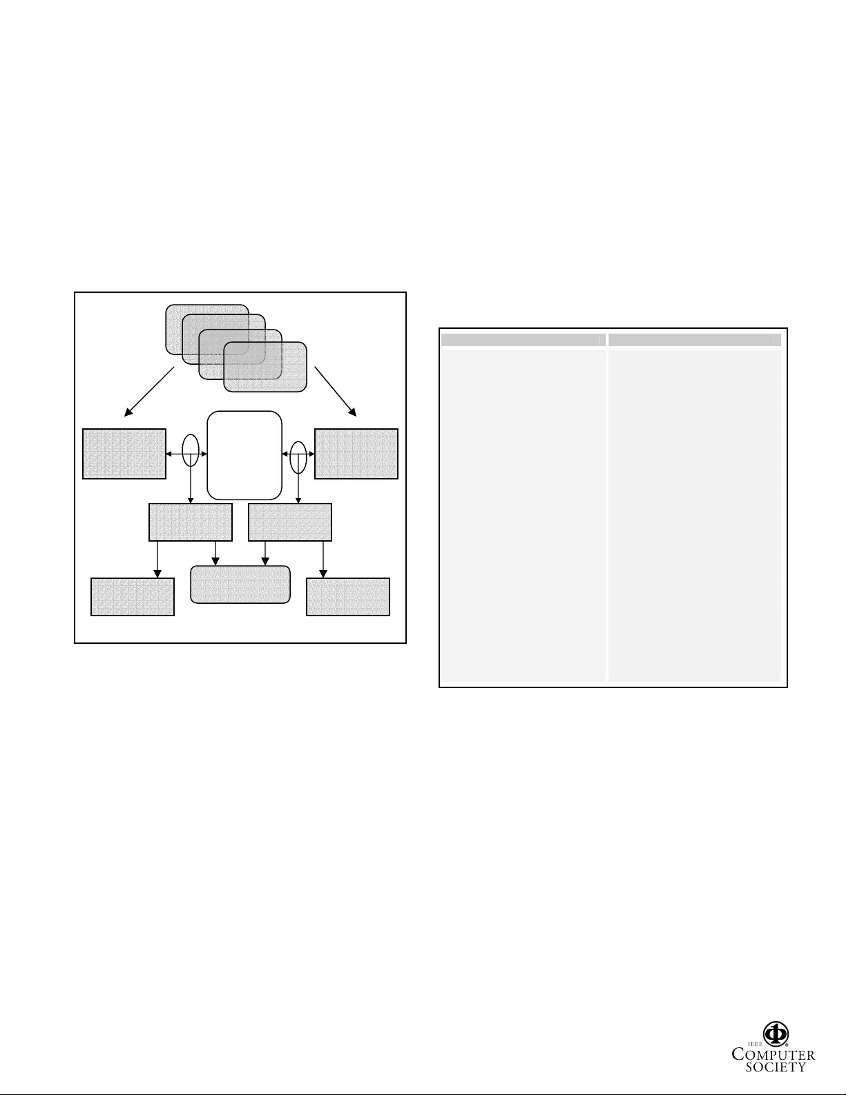
Common Reusable Verification Environment for BCA and RTL Models Giuseppe Falconeri, Walid Naifer, Nizar Romdhane STMicroelectronics - OCCS (On Chip Communication System s) Abstract This paper deals with a common verification methodology and environmen t for SystemC BCA and RTL models. The aim is to s ave effort by avoi ding the same work done twice by different p eople and to reuse the same environment for the two design views. Applying thi s methodology the verification task starts as soon as the functional sp ecification is sign ed off and it ru ns in parallel to the models and design development. The verification environment is modeled with the aid of dedicated verification languages and it is applied to both the model s. The test suite is exactly the same and thus it’s possible to verify the alignment between the two models. In fact the final step is to check the cycle-by-cycle matc h of the interface behavior. A regressi on tool and a bus analyze r have been d eveloped to help the verification and the alignment process. The for mer is used to automate the testbench generation and to run the two test suites. The latter is used to verify the a lignment between the two models comparing the wavefo rms obtained in ea ch run. The quality metrics used to va lidate the flow are full functional coverage and full a lignment at each IP port. 1. Introduction Nowadays, System On C hips are increasing in term s of co mple xi ty a n d ti me to mar ke t is be co min g mor e a nd mor e critical and functional verification is a bottleneck. Development tim e of such activity takes 80% of design effort. This effort is mainly spent to test RTL design, since it will be the circuit to map on silicon. Th e introduction of BCA development in the flow is becom ing wider. The fast simulation of BCA models perm its to fast find the optimized configuration, in term s of bandwidth, area and power consum ption. Therefore, these models are becoming key elements in SoC devel opment and the const raints in terms of functional poin t view are similar to RTL, that’s why it is necessary to have the powerful verification environment also for the models. Moreover having a common verification environment that is reusable for both BCA and RTL can give a big benefit. The idea of the comm on verification environm ent is not new [1] and we want to follow thi s new strategy because of the gains in terms of development tim e and accuracy of the verification since the random traffic and automatic checkers can be applied for both the views of the design. In this paper the comm on verification environm ent developed for the dynamic functional veri fication of the STBus 1 [2] compone nts is described. 2. The Past flow In the past there was no strategy for a common verification of the two views of the IPs. The BCA model verification and the RTL ve rification were two different activities managed by two or m ore different teams. In fact in the verification of the BCA models the test bench was developed by the m odel owner and occ upied a short time of his whole activ ity. It was based on a very basic model of harnesses written in SystemC and doing write then read operations to wards a memory model. The tests cases were directive and allowed checking particular features of the design. And a lot of checks were done visually. On the opposite the verific ation of RTL model was based on Veri sity Specman [3] tool allowing random generation and automatic checks that cover all functiona l rules. Whole activity was perf ormed independently from design. The fact that verification environment was handled by the BCA model owner ma kes self-error detection m ore difficult. The test bench was also not strong enough to reach corner cases. Othe r drawbacks we re that the effort spent to develop verification e nvironment was duplicated in RTL and BCA developm ent and there was no way to understand “quality metrics” lik e coverage for BCA so a new strategy for the verification becomes fundamental. 3. STBus Overview The aim of this section is to introduce the STBus, the communication system develope d for Syst em-On-Chi p in 1 STMicroelectronics proprietary on-chip bu s` Proceedings of the Design, Automation and Test in Europe C onference and Exhibition (DATE’05) 1530-1591/05 $ 20.00 IEEE ST. The STBus is a set of protoc ols, interfaces and architectural specifications defined to implem ent the communication netw ork of digital system s such as microcontrollers for differen t applications (set-top box, digital camera, MPEG decoder, GPS ). The STBus protocol consists of three different types (namely Type I, Type II and Type III), each one assoc iated with a different interface and capable of differing performance levels. x Type I is a simple synchronous handshake pr otocol with a limited set of available command types, suitable for register access and slow peripherals. x Type II is more efficient than type I because it supports split transactions and pipelin ing. The transaction set includes simple read/write operation with di fferent sizes (up to 64 bytes) and also specific operations. Transactions may also be group ed together into chunks to ensure allocation of the slave and so ensure no interruption of the data stream. It is typically suited for External Memory controllers. A limitation of this protocol is that the traffic m ust be ordere d. x Type III is the most efficient, because it adds support for out-of-orde r transactions and asymmetric communication (length of re quest packet different from the length of response packet) on top of what is already provided by Type I I. CPUs, m ultichannel DMAs and DDR controllers can therefore use it. All the initiators and the targets must have one of these three interfaces and they can communicate each othe r independently of the type use d because type converte rs into the interconnect (Figure 1) ca n be used. Figure 1: Example of communication net work (interconnect) within a SOC The STBUS provides also the size conversi on when the initiators and targets have di fferent data bus size. So the STBus is the block to which all initiators and targets must be connected and it perform s conversions, arbitration and routing. The arbitration is the pro cess consisting of deciding which in itiator, among the on es asking to start a transmission, can take po ssession of the bus; the latter consists in the propagation of the signals across the bus from an initiator interface to a target i nterface. A wide variety of arbitration po licies is also available, to help system integrators meet initia tors and system requirements. These include bandwidth limitation, latency arbitration, LRU, priority-bas ed arbitration and others. This is one of the main characteristics of the STBUS. It’s not only a single bus or a set of buses, but it can be a hierarchical comm unication network com posed of m ore than one router. Moreover the various p arts of the interconnect can have di fferent wi dth of dat a bus, different speed and diff erent comm unication protocol. T his can be done connecting a set of 4 basic compone nts: nodes, size converters, type convert ers and register decoders . In the following picture a n example of an interconnect containing nodes (responsible for routing and arbitration) and some converters is shown. The architecture of the STBUS is not fixed, but can be different device by device . According to the system requirements it is possible to choose a single shared bus, that gives the better results in term s of wiring co ngestion and area occupations, but can lead to worse results in terms of performance, or a crossbar (f ull or partial), that leads better results in terms of perform ance of the system, but worse results in terms of area and wiring congestion. In thi s case two different transactions in the same time are possible 4. Common Verification Flow Since the BCA and the RTL m odels have the sam e requirements in terms of functional ve rification (with respect to the specificatio n), it is convenient to have common verifi cation flow for both RTL and BCA. T hese requirements are: o Random traffic ge neration o Automatic Check on protocol interfaces o Automatic Check on da ta integrity: the DUT (Design Under Test) outputs’ data correspond to th e inputs’ one, with respect to the specifications o Functional and Code Coverage Metrics In this section the common verification flow used for both BCA and RTL is described. T he goal is to have a unique verification envir onment so that the effort spent to develop it is done only on ce and not duplicated as in the past. The verification environm ent developm ent should not depend on the model data ty pe (BCA or RTL). To be efficient, verification activity mu st be done by a third part, Initiator 1 Initiator 2 Initiator 3 Target 4 Target 1 Target 2 Target 3 Initiator 4 64/32 Node (type2, 32 bit) t2 / t3 Node (type3, 32 bit) t2 / t3 Proceedings of the Design, Automation and Test in Europe C onference and Exhibition (DATE’05) 1530-1591/05 $ 20.00 IEEE to be independent from other activities. The functional specifications must be the only reference of verification implementation. The BCA or RTL verifi cation activities could also serve to correct verification implem entation. In fact some bugs could be given by verification environment. The common part of the test bench is completely developed i n ‘e’ language an d the BCA or the RTL m odel can be plugged in it. The architecture of the test bench (Figure 2) is standa rd and it’s described in t he picture below. All the gray com ponents are written in ‘e ’ code and the DUT can be RTL or BCA. Figure 2: Generic Testbench Ar chitecture The DUT interfaces are connected t o eVCs (e Verification Components) written in ‘e’ code. Each eVC is endowed with BFMs that generate random scenarios, monitors that collect traffic information and checke rs that check the correctness of the protocol at the interface. Moreover the s coreboard and specific c heckers are required for each DUT to verify the correct beha ving of whole according to the verification plan. In order to test particular features of the design, some specific test files need to be developed. Sam e test file could be run m ore than one time with a different seed. The aim is to reach a full functional and code coverage rate. For the STBus interfaces ST has develope d an ‘e’ code generic library called CAT G (Checkers and Aut omatic Test Generation) aim ed to test component havi ng STBus interfaces. It contains models of STBus harnesses, monitors, protocol chec kers and a score board for dat a comparison. It has also a det ailed functional coverage related to the STBUS. This environment is configurable according to the DUT configuration, in term s of bus size, protocol bus type, pipe si ze, endianess and s ome other parameters. It’s plugged with DUT, using NCSim ’s Cadence Simulator. All test bench files except of Specman’s ‘e’ files are c ompiled and elaborated to give a snapshot to be called by NC Sim and Specm an tools, at same tim e. Specman’s environm ent is plugged to NCSim ’s VHDL simulator via a pr ovided VHDL wrapper file. This wrappe r is called by VHDL test bench file, which contains signals declaration and clocks proc esses. Except of cl ock, all signals are driven by eVCs ATTRIBUTE FOREI GN OF Figure 3: Wrappers code for Sy stemC models For what concern the BCA DUT verification an extra work is required in order to connect th e model to the common test bench. In fact, CATG library was developed with an old ap proach not taking in to account the port approach, recently introduced by Specm an to directly plug SystemC simulator with ve ri fication environm ent. Since many simulators are now able to support SystemC and VHDL design, CATG has been interfaced with SystemC model through VHDL test benc h file. However, sinc e VHDL simulator is used, t he advantage of havi ng fast SystemC simulator is lost. To interface SystemC simulator and VHDL one, a VHDL wrappe r is required, accordi ng to Cadence approach. It is similar to the SystemC top file for what concerns signals declaration and m odule name, and it refers to SystemC model in its architecture (Figure 3). The VHDL test bench is the same as de veloped for RTL model. DUT (RTL or BCA) Scoreboard Test1 Test 2 Checker Checker Monitor Monitor Harness1 Interface Harness2 Interface Test 3 Test N SystemC top file node:_top.cpp VHDL wrapper : node_top.vhd #include sy stemc.h #include bca _node.h SC_MODULE(node_top) { // ports decla ration: sc_in req; sc_in< sc_ui nt<64> > da ta; : : // model declar ation bca_node *com ponent // constr uctor SC_CTOR(node_top): req("req"),data("data") { component->req( req); component->data (data); }; }; // Cadence’s s pecific syn tax NCSC_MODULE_EXPORT(node_ to p); LIBRARY ieee; USE ieee.std_logic_1164.all; ENTITY node_top IS PORT ( req : IN STD_LOGIC; data : IN STD_LOGIC_VECTOR(63 : downto 0); : : ); END node _top; -- referring to Syst emC model ARCHITECTURE SystemC OF node_top IS SystemC : ARCHITECTURE IS "SystemC"; BEGIN END; Proceedings of the Design, Automation and Test in Europe C onference and Exhibition (DATE’05) 1530-1591/05 $ 20.00 IEEE It has the same signals declaration and instantiates the VHDL’s wrap per compone nt and the sam e Specman’s wrapper of the RTL model test bench. The com pilation process follows Cadence m ethodology [4]. As verification environm ent, test benches, wrappe rs and models’s configuration files n eed to be configured according to model confi guration. The regression tool, which is deve loped internally to run regressi on flow, generates and compiles these files. It consists on a graphical user interface able to receive configuration parameters. It runs re gression tests in batch mode, through generic scripts that are design independent. For eac h test file associated with the test seed, a veri fication report and a functional coverage one are generate d. Moreover, an associated VCD file, a standa rd format for wa veform recording, is generated so that it can be used later for bus accurate comparison. Figure 4: Common Verification Flo w The quality of the verifi cation is measured using coverage m etrics. Both functional a nd code cove rage m ust be checked in order t o be sure that the design is correctly verified. The fun ctional coverage is built i n the common verification environment and it can be obtained in both RTL and BCA models (of course they must be equal running the same tests). The code coverage reflects how the code is exercised and can be applied only in the RTL verification since no tool is able to generate this metrics for SystemC. The code coverage m etrics we use are line, branch and statem ent coverage. Our goal for the verification of the blocks is 100% of the functional coverage defined and 100% of ju stified code f or the line coverage, whil e in general we acce pt less for the ot hers code coverage metrics. Figure 5: Common Verification Step by Step The quality of the verifi cation is measured using coverage m etrics. Both functional a nd code cove rage m ust be checked in order t o be sure that the design is correctly verified. The fun ctional coverage is built i n the common verification environment and it can be obtained in both RTL and BCA models (of course they must be equal running the same tests). The code coverage reflects how the code is exercised and can be applied only in the RTL verification since no tool is able to generate this metrics for SystemC. The code coverage m etrics we use are line, branch and statem ent coverage. Our goal for the verification of the blocks is 100% of the functional coverage defined and 100% of ju stified code f or the line Functional Specifications Verification implem entation RTL model verification Bus accurate comparison BCA model verification Stable functional spec Full coverage Low alignment rate Compile verification environment Create Specman’s wrapper file Create SystemC top file including bca_model.h Create VHDL wrapper file Create VHDL test bench Compile and link SystemC files Run simulation on BCA model and analyze results For BCA model Create Specman’s wrapper file Create VHDL test bench For RTL model Compile VHDL files Compile VHDL files Run simulation on RTL model and analyze results Compare VCD results if full functional coverage BCA model passed RTL model passed Elaborate testbench using ncelab with a link to systemc.so library Elaborate testbench using ncelab Proceedings of the Design, Automation and Test in Europe C onference and Exhibition (DATE’05) 1530-1591/05 $ 20.00 IEEE coverage, whil e in general we acce pt less for the ot hers code coverage metrics. Having BCA model fully verified with full functional coverage does not guara ntee that it’s exactly behaving as RTL one, at bus cycle accuracy. This sp ecially happens when the specifications do not constraint signals behavi or, so that checkers cannot veri fy such constraints. A second quality metrics consists on getting bus accurate comparison between both models. STBus Analyzer (STBA), an STBus internal tool, com pares signals information at each port level. It is automatically called by the regr ession tool a nd it extracts from VCD files, got after regressi on tests, STBus transaction information. The rate that is cal culated at each port level is the number of cycles RTL and BCA signals port are aligned over total number of clock cycles. The targeted value, in order t o consi der BCA model signe d off is 99%. The Figure 4 shows t he comp lete flow beginning fr om functional specification down to the bus accura te comparison, while the Figure 5 summ arizes steps necessary to implement and to run test bench for both RTL and BCA activities. 5. Test case An example of how this flow ha s been applied in our team is the verification of the STB us node. The STBus node is the key IP of an STB us interconnect system. It is in fact responsible for perform ing the arbitration am ong the requests issued by the initiators of the system, and among the response-requests issued by the targets of the system, and for the routing of the information from the initiators interfaces to the targets interfaces, and vice versa from the targets interfaces to the initiators interfaces. Supporting either Type 2 or Type 3 STB us protocol, the Node can manage up to 32 i nitiators and 32 targets and its data interface width varies from 8 to 256 bits. It ca n have three different architectures: shared bus, full cross bar or partial crossbar. The Node su pports 6 arbitration types as Less Recently Used or Latency based. It has an optional programmable port allowing chang ing the arbitration priority of initiators or targets. The verification of the Node takes advanta ge from CATG library. Specific checks, not covered by CA TG, have also been devel oped. The Figure 6 shows a Node with three initiators and two targets. Each harness has its own monitor collecting sign als information. STBus protocol interface rules are checke d for each port through protocol checkers based on c orrespondent monitor. In order to test verify data flow integ rity between initiators and targets, the scoreboard com pares results got form monitors. Harnesses, Monitors, Protocol checkers and scoreboard are all provided by CAT G library. Twelve test cases have bee n develope d to cover the tests of all main features of the node suc h as out of order traffic or latency based arbitration. They allow initiators to generate semi-random traffic. To force out of order traffic for example, short transactions are sent by one initiator to different targets, havi ng different speed. The test cases are generic a n d depend on som e HDL parameters. They can be reus ed for all configurations of the Node. Figure 6: Node Test bench The Regression tool gene rates VHDL and SystemC files according to used c onfiguration of the Node. HDL Parameters are submitted through a graphical user interface. The tool also launches parallel regression tests on BCA and RTL models. It a pplies same test cases on both with same seeds. So that it can later, proceed to alignm ent comparison activity, if all checkers passed. Since Node has m any configura tions, regression tool can load text files defining HDL param eters of each of them. It’s sufficient to indicate the directory to which the tool has to point. More than 36 configu rations of the Node have been tested. The verification envi ronm ent permitted to find five bugs on BCA models, not foun d using old environm ent of the past flow. It added more confidence on the BCA mode l to be delivered to STBus custom ers. 6. Conclusion The verification of the Syst em C models is now a key factor to have exact simulati on results. A lot of effort has been done in the past in order to improve the RTL verification using specialized verification languages. The goal is to exploit this effort also for the models verification and spend some effort in order to gene rate a common verification environm ent reusabl e for t he two views of t he Node (DUT) Initiator 1 Initiator 2 Initiator 3 Target 2 Target 1 Programm ing Initiator Scoreboard Protocol checkers Protocol checkers Monitors Monitors Proceedings of the Design, Automation and Test in Europe C onference and Exhibition (DATE’05) 1530-1591/05 $ 20.00 IEEE design. Moreover it’s important to give the visibility to the customers that th e adopted strategy in the verification of both models is the sam e. This has been reached quite easily obtaining good results in term s of time spent in the development of th e common environment a nd in the ab ility to find bug in both BCA and RTL. In the future this approach will become more a nd m ore important so this methodology will be applied in all the STBus activities. The future availability of the next version of CATG supporting ports appro ach will make possible a direct interfacing of System C simulator with Specman’s environment. This shoul d en hance simulation performance. Future including of SystemC Verification in ve rification flow will be a great opportunity to add TLM (Tran saction Level Modeling) development and verification phase in the flow. References [1] “From Behavio ral to RTL Design Flow i n SystemC “, Emma nuel Vaumorin, Thierry R omanteau - http://www.us.designreuse.com/articles/ article7354.html [2] "STBus Functional Specs", STM icroelectronics, public web support site: http://www.stmcu.com/inchtml-pages-STBus_intro.html STMicroelectronics , April 2003 [3] Verisity Specman User Guide [4] Cadence Ncsim User Guide Proceedings of the Design, Automation and Test in Europe C onference and Exhibition (DATE’05) 1530-1591/05 $ 20.00 IEEE
Original Paper
Loading high-quality paper...
Comments & Academic Discussion
Loading comments...
Leave a Comment