A graphical environment to express the semantics of control systems
We present the concept of a unified graphical environment for expressing the semantics of control systems. The graphical control system design environment in Simulink already allows engineers to insert a variety of assertions aimed the verification a…
Authors: Timothy Wang, Romain Jobredeaux, E. Feron
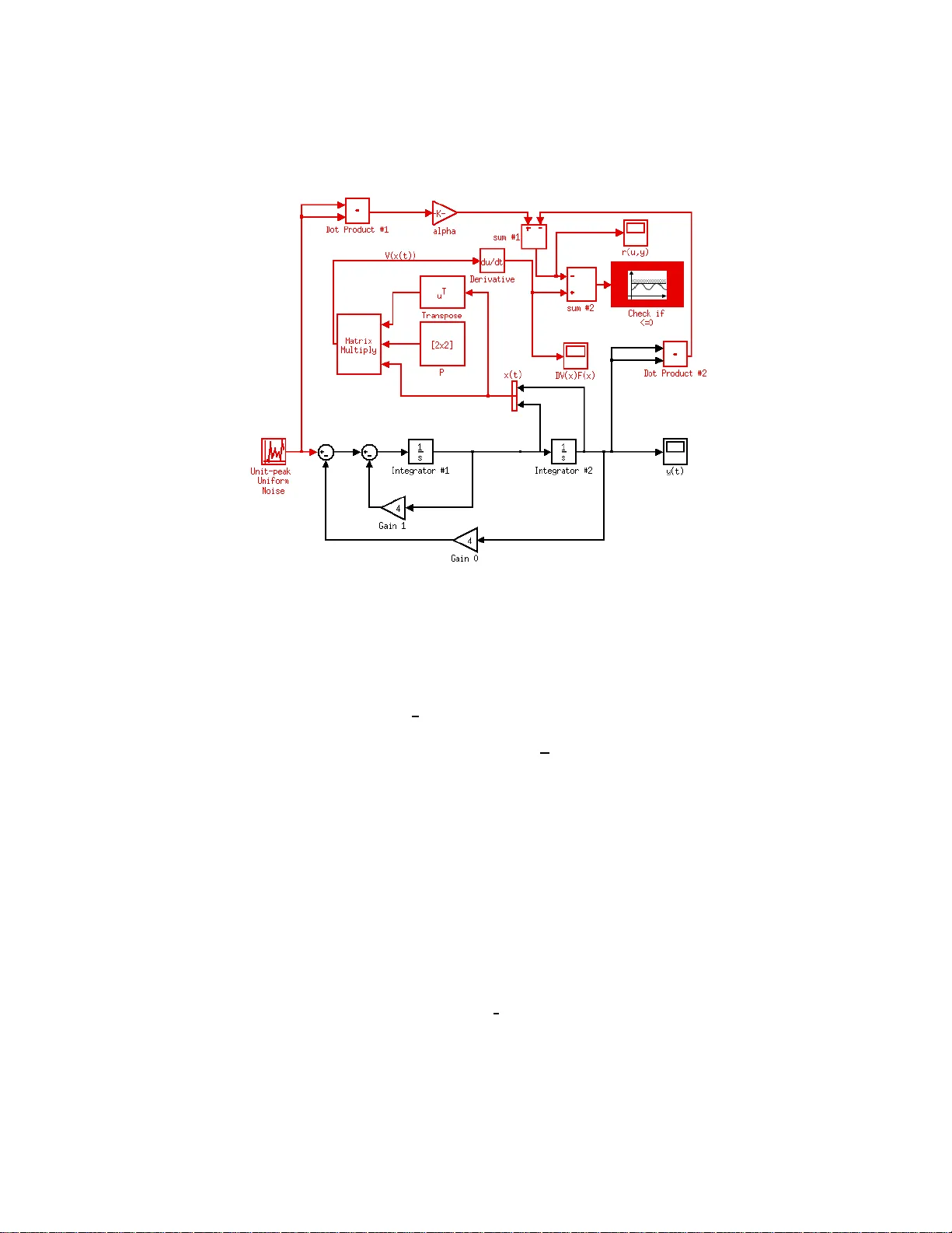
A graphical en vironmen t to express the seman tics of computer-con trolled systems Timothy W ang ⋆ , Roma in Jobrede ux ⋆⋆ , a nd Eric F ero n ⋆ ⋆ ⋆ Georgia Institute of T ec hnology , 225 North Ave nue, Atlan ta, Georgia 30332-0001 Abstract. W e presen t the concept of a unified graphical environmen t for expressing the semantics of control systems. The graphical control system design environment in Simulink already allows engineers to in- sert a v ariet y of assertions aimed the verification and v alidation of the contro l so ftw are. W e prop ose extensions to a Simulink-like environmen t’s annotation capabilities to in clud e formal control system stabilit y , p erfor- mance prop erties and their proofs. W e provide a conceptual description of a tool, th at takes in a Simulink-like diagram of the control system as the inpu t, and generates a graphically annotated control system diagram as the output. The ann otations can either b e inserted by t h e user or gen- erated automatical ly b y a th ird party control analysis sof tw are such as IQC β or µ -tool. W e finally d escribe ho w the graphical representation of the system and its properties can b e translated to annotated programs in a p rogramming language used in verification and v alidation such as Lustre or C. 1 In tro duction Embedded control systems are ubiquitous in presen t day sa fet y-critica l applica- tions. The aerospace and medica l fields a re filled with examples of suc h systems. The verification and v a lidation (V&V) of their soft ware implementation has a l- wa ys been a ma jor preo ccupation given the dire c o nsequences of a ny p otential malfunction. It has b een the endeavor of the formal metho ds communit y to pro- vide to ols that facilitate and rationa lize this pro cess. How ev er, currently there is little communication b etw een the engineers who design the control sys tem and the engineer s who do the V&V. It has been noted in [5 ] that the former could po ten tially provide v alua ble inputs for the latter in rega rds to finding the rele- v an t in v arian ts. W e be lieve that inputs from the control engineer can b e helpful to the V&V communit y if the following can b e pr ovided: ⋆ Timoth y E. W a ng is a PhD candidate in the Aerospace Engineering Department at Georgia Institute of T ec hnology gtg176i@mail.gatec h.edu ⋆⋆ Romain Jobredeaux is a PhD Stud ent in the Aerospace Engineering Department at Georgia Institute of T ec hnology rjobredeaux3@gatec h.edu ⋆ ⋆ ⋆ Dr. Eric F eron is the Dutton-Ducoffe Profe ssor of Aerospace Engineering at Georgia Institute of T echnolog y feron@gatech. edu – An environmen t for the con trol engineers to easily insert s ta bilit y and p er- formance pr o ofs into their designs. – Automatic translation of the information provided b y the control engineers int o a form that is familiar to the V&V communit y . In this pap er, we pre sent an extension to the curr ent blo ck diagr a m represen- tations of control systems (Sim ulink, Xcos) that include fundamental con trol systems pro of information such as a L yapunov function, which establishes sta - bilit y , a nd the plant mo del with resp ect to which s tability was es ta blished at the time the con troller was designed. These extensions resemble, but are different from, Simulink’s curr e n t diagr am annotation capabilit y . 1.1 Challenges The following are the challenges that we like to addres s: – Provide a coherent set of new blo cks in a S imulink-lik e environmen t that enable a wide arr ay of systems and t ypes of stability pro ofs to be handled. – Provide a for ma l semantics for the new gr aphical environmen t. The seman- tics ca n b e inherited from a Simulink-like environment tha t has a fo r mal semantics suc h as Scade. – Dev elop a tool to per form translatio n from the Simulink-lik e environmen t to an industrial progra mming la nguage such as Lustr e or C. 1.2 Bac kground Sim ulink b eing the de-facto industry to ol for embedded controllers, has b een the sub ject of many research efforts in the v alidation and verification c o mm unity . There hav e be e n numerous a ttempts at the tra nslation of Simulink in to other languages for the purp ose of forma l a nalysis. See [1], [10],[2 ] and [12]. The ideas presented in this pap er are not specifica lly confined to Simulink, but rather they form an ov erall conce pt tha t can b e implement ed in any g raphical mo deling language to ol. This work is closely rela ted to the ideas pr esented in [5], as it explores auto co ding with pro of at the in terface with the control engineer. 2 Conceptual Overview W e beg in by pr op osing a to ol represented by the illustration in figur e 1. The front-end of the to ol provides a unified g raphical e n vironment for the design of control systems as well as the insertion of pro o fs ab out the control systems. The back-end transla tes the v is ual design with pro ofs in to anno tated co de in an industrial prog ramming language, such as Lustre or C which can then b e analyzed using V&V to ols developed by the for ma l metho ds co mm unity . W e describ e the top-lev el comp onents that make up the tool with the fo c us on the graphical environmen t for the expression of control systems sema ntics. The demonstrations in this pap er use existing annotative capabilities of the graphica l mo deling platform Sim ulink. V er ification Block Generator Input: Controller design in the simulink language Output: annotated code in Lustre or C Output Input Visualization of the Simulink Model for manual insertion of annotations T ranslator to C or Lustr e with annotations Simulink Language extended with stability proof and peformance annotations 3rd P arty Control Analysis Software Simulink Model of the Control System Fig. 1. Over all Picture 2.1 F ront-end The front-end of the to ol takes in a n input o f a Simulink-like mo del and feeds to the verific a tion blo ck gener ator (the green blo ck in fig ur e 1 ). L e t us consider the mo del of the double integrator sy stem in figure 2 a s the input. The verific ation blo ck gener ator pr o duces an output mo del that includes a dditional blo cks a nd wires (see the red por tion in figur e 3), whic h are ar ranged to expres s an a sser- tion o n the s tates of the input model. The Sim ulink en vironment gives the user great flexibility in expressing a v ariet y of stabilit y and p erformance criter ia from control theory literature. In this particular example the verific ation blo ck chec ks the stability of the double integrator system in the presence of a no ise that is bo unded in p ow er. How ever, note that the stability pr o of annotation in figure 3 was constructed by concatenating tw o signals together, and then feeding the output through several mathematical and logic blo cks from the Sim ulink library . This can beco me a very cum be r some pro cess to the control engineer. T o simplify this a s m uch a s p ossible w e pr op ose an extensio n to the current Simulin k block library to allow a more dir e ct way o f expr essing co nt rol systems pro per ties and their pro ofs. F or exa mple the b ounded noise stability prop er ty in figure 3 can be captured more suc c inc tly b y a new a nnotation blo ck type denoted stability with the following three parameters : the positive-definite matrix P , the charac- teristics of the noise input and the states of the control system. More examples and detailed descriptions of the v a riety of cont rol systems prop erties and pro ofs can b e found in section 3. Fig. 2. Mo del In put Fig. 3. V erification Block Generator Output 2.2 Automatic Generation of Con trol System Pro ofs The most impo rtant par ameter in the prop osed stability blo ck type is the p ositive- definite matrix P s inc e stability proo fs for many co n trol systems boils down to computing this matrix [4], a nd the pro o f flo ws do wn to the co de-level in a nice fashion [5 ]. T o automate this pr o cess as m uc h as p ossible w e pro po se linking the verific atio n blo ck gener ator with auto ma tic control system ana lysis to ols (s e e the pink blo ck in fig ure 1). Several third party to ols exist which can adapted for this role. F or linea r con trol systems the P can alwa ys b e generated automatically by a robust control to olb ox suc h as the IQC β or µ -to ol (see [9 ],[1 1] and [3]). F or nonlinear co n trol systems such a s adaptive co nt roller s it is lik ely that manual input will b e needed. F or exa mple the user might b e expected to insert the Lya- punov function b y using the appr opriate Sim ulink blo cks and connecting them with the wires. F or thes e ca ses wher e the automatio n fails, the mode l output from the verific atio n blo ck gener ator is provided to the user as the in terface for the manual insertions of the sta bilit y proo fs (see the gray blo ck in fig ure 1). 2.3 F orm alism W e prop ose a new type of wir e that elev ates sig na ls to the abstract level to allow easy differe n tiation b etw een signals that repres en t the states of the control system i.e . x ( t ) in figure 3 and signals that are not the states of the co n trol system. The res t of the newly propos e d annotatio n blo ck types can use the existing blo cks and wires structure, with some indication that they are not to b e used for co de genera tion, but for annotation generatio n. F or this w e also pro po se an intermediate lang uage repres en tation of the Simulink mo del tha t makes this distinction clearly . The existing lab eling options that ex is t in Simulink can be useful her e to k eep track of na mes. 2.4 Bac k-end The back-end of the to ol is the translator from the graphical environmen t to a progra mming la nguage such as C or Lus tr e. The ma jority of w ork here is will b e formalizing the s emantics of the g raphical environment. The tr anslation pr o cess m ust also deal with time discretization of the stabilit y pr o of annotations, whic h can b e quite difficult dep ending on the t ype o f control sys tem that the user put int o the too l. 3 Sim ulink E xamples W e pr esent several examples of a nnotating sta bilit y pr o ofs and p erfor mance criteria for c ontrol systems in the Simulink environment. These exa mples can obtained from control engineering b o oks such a s [8 ] o r [6]. 3.1 Seman tics of the Simulink blo cks and wires The mathematical op erationa l blocks such as sum, mult iply , divide, dot pro d- uct are p olymor phic just like every other Sim ulink blo cks. They take input ar - guments of ma ny different types : scalar, vector of arbitrar y dimensions, and matrices. Semantically the blo cks can change either due to differen t input ar gu- men ts or user spec ification. F or example the ”Pro duct” block can be a pro duct of scalar s, matrix m ultiplication, or element-wise m ultiplication of the ent ries of the vector depending on the input ar gument and user choice. The wires can carry all n umerical data types av a ilable in Sim ulink. The t wo r elev an t t ypes in the control sy stem diag rams are scalars and vectors that are assumed to be either real or co mplex . F o r expressing mo st annotations of sta bilit y pro ofs and perfor- mance cr iteria, we can use the exis ting blo cks in Simu link. A s mall amo un t o f annotations may require the conv enience of functions defined outside o f Simulink environmen t i.e. MA TLAB for ex ample. 3.2 Ly apuno v Stability W e start with Lyapuno v stabilit y , since it is the simplest stabilit y result in time- domain that we can expres s using the graphical environment o f Simulink. The essential part of the Lyapunov stability is the quadratic Ly apunov function V ( x ) in (1) wher e x is the sta te of the control system and P is a p ositive-definite matrix. V ( x ) = x T P x (1) The noise blo ck is set to 0 . The verific ation blo ck shown in figur e 4 expresses the following assertion: the lie deriv ative o f the Lyapunov function V ( x ( t )) is les s than or equal to z ero. T he matrix P can b e co mputed using either one of the t wo robust co n trol to olb oxes mentioned. 3.3 L 2 Gain Stabili t y F or input-to-output stabilit y , the annotatio n diagr am b ecomes more complex. In this case bo th the s torage a nd supply functions need to b e co nstructed [6]. Figure 5 has an example of a pro of annotation showing finite L 2 -gain stability of the double int egra tor system. The annotation expres s es the following as s ertion: ˙ V ( x ) − α 2 w T w + y T y ≤ 0 (2) where w is the unit-p eak uniform nois e input, V ( x ) = x T P x is a quadra tic Lyapuno v-like function called the storage function, and y is the output sig nal. The prop osed ex tensions to the interface will reduce dra stically the num ber of blo cks and wire s necessar y to co nstruct this stability pro of a nnotation. Despite the incr ease in complexity one o f the essential comp onent of the annotatio n is still a p ositive-definite matrix P . This P ca n also b e obtained us ing the tw o robust control solvers mentioned in section 2, ther efore the diagram in figure 5 can b e generated automa tically . Fig. 4. Ly apunov S t abilit y 3.4 Plan t M o del as Annotation Most controller stability pro ofs are based o n s ome form of model for the pla nt that is being con trolled. Thus the plant needs to be in tro duced so mehow in the annotation fr a mework. This is actually relatively stra ig ht forward at the gr aphical level, since most gra phical mo deling tools are not only mean t for implement ing controllers, but also for testing them, and in the latter case a mo del for the plant must b e present. Figure 6 shows how we go ab out displa ying pla nt mo del information a t an abstra ct level, whic h will not interfere with the ex ecutable co de that will be generated. W e take the example of the following plant fro m [7] m ¨ x + c 1 x 2 − c 2 ˙ x + k 1 + k 2 x 2 x = u (3) with the adaptive con troller u = ψ x ˙ ψ = − B T 0 P x 2 x ˙ x x ˙ x ˙ x 2 (4) Fig. 5. Finite Gain L 2 Stable The Lyapuno v stability of the feedback interconnection of the plant and the controller is established b y the Ly apunov function V ( x, ˙ x, ψ ) = 1 2 x ˙ x T P x ˙ x + p 2 Z x 0 σ ˜ K ( σ ) dσ + p 12 Z x 0 σ ˜ C ( σ ) dσ + 1 2 ψ ψ T (5) This complex example is mainly introduced to show the almos t unlimited expressive power of the pro po sed in terface extension. 3.5 L 1 Adaptiv e Co n troller Performance T o further demonstra te the expre s sive p ow er of the gr aphical environmen t, we show the following L 1 adaptive controllers (see figure 7) and an example o f an- notating a p erforma nce b ound. F or L 1 controllers there exis ts a pro of of not only closed-lo op Lyapunov s tabilit y but also b ounds o n the trans ien t p erformance s. F or example the b ound on the state prediction er ror ˜ x of the controller is a func- tion of the uncertain ty of the pla nt ”theta max”, the Ly apunov function matrix P and the a da ptive gain ”Gamma” . Note that the uncer taint y pa r ameter of Fig. 6. Adaptive control ler with Plan t plant can b e part of the plan t mo del or separa te b y itself as in figure 7. k ˜ x k L ∞ − s θ max λ min ( P ) Γ ≤ 0 (6) 3.6 Discretization during T ranslation Thu s far we have sho wn sev eral examples of contin uous-time pro ofs of stability for control sys tems. Now ho w do these pr o ofs tra ns late down to the co de-level? The main iss ue as mentioned befo r e is the time-discretization that is applied to the mo del when it is transla ted in to co de. F or tuna tely for all linear cont rol sys - tems, the discrete-time stabilit y pr o ofs can be easily and sy stematically obtained How ev er for the adaptive controllers, it is very impractical to lo ok for Lyapunov stability pro o fs in discr ete-time hence the problem remains that we must us e the contin uous-time pro ofs as in v arian ts for the discretized system. 4 In tegration wit h Third P art y T o ols F or the integration o f third party control system analy sis to o ls , w e’ll need to build a comp onent that extra cts the necessary c o nt rol system para meters a nd characteristics fro m the input Simulink mo del. F or this pro cedure to b e auto- mated it is again necessary to ha ve a formal semantics of the prop osed graphi- cal environment. System infor mation such as the state-space model, the system states, the input nois e disturbanc e are exa mples of the requir ed inputs nee de d for IQC β and µ -tool. Fig. 7. L 1 T ransient Performance Boun d 5 Conclusion and F uture W ork In this pap er we have prop osed a new gra phical environment that allows the easy expression of the semant ics of computer-controlled sys tems. W e believe this environmen t simplifies the pro cess by which the control eng ineer can pr ovide do- main k nowledge for the deductive verification of the controller implementation. W e ha ve provided several exa mples of how control stability pro o fs and p erfor- mance criteria can be expresse d in a curre nt gra phical mo deling environment i.e. Simulink. F or the new gr a phical environmen t, we have propo sed several ex - tensions designed to enha nc e the pro o f annotative capabilities of the cur rent environmen t. W e are currently in the pro ces s of formalizing the new unified graphical environment . This is a prop osed resear ch o r ientation that still requires m uch effort: formalizing the gr aphical annota tion ”la nguage”, integrating it in an existing g raphical mo deling environment, interfacing it with third party to ols, and las tly implementing the transla tion to ol that will gener ate the annotated co de from the extended diagrams. 6 Ac kno wledgmen ts This resea r ch is suppo rted by the Northeaster n Universit y and NASA, b y the United Sta tes Army throug h the contract W911NF-11 -1004 6, and by Auro ra Flight Sciences throug h the co nt ract AFS10- 0036. References 1. M. Ad ams, P . Cla yton, and N. T udor. Cla wz: cost-effective formal verificatio n for contro l systems. In Digital A vionics Systems Confer enc e, 2005. DASC 2005. The 24th , vo lume 2, page 10 pp. V ol. 2, oct .- 3 no v. 2005 . 2. A. A gra wa l, G. Simon, and G. Karsai. S eman tic translation of sim ulink /stateflo w mod els to hybrid aut omata u sing graph transformatio ns. I n International Work- shop on Gr aph T r ansformation and Visual Mo deling T e chniques , page 2004 , 2004. 3. G. J. Balas, J. C. Doyle, K. Glo ver, A. Pac k ard, an d R. Smith. mu-analysis and Synthesis T o olb ox , 1993. 4. S. Boyd, L. E. Ghaoui, E. F eron, and V. Balakris hnan. Li ne ar Matrix Ine qualities in System and Contr ol The ory . Society for Ind ustrial and Ap plied Mathematics, 1994. 5. E. M. F eron. Certifying con trol-system softw are integrating pro ofs into real-time prod ucts. Contr ol Systems Magazine , 2010. 6. W. M. Haddad and V. Chellaboina. Nonli ne ar Dynamic al Systems and Contr ol : A Lyapunov-Base d Appr o ach . Princeton Universit y Press, 2008. 7. T. Ha yak aw a. Dir e ct A daptive C ontr ol for Nonline ar Unc ertain Dynami c al Sys- tems . PhD thesis, Georgia Institute of T echnology , 2003 . 8. N. Hov akimy an and C. Cao. L1 A daptive Contr ol The ory Guar ante e d Rob ustness with F ast A daptation . SIAM, 2010. 9. U. Jonsson, C.-Y. Kao, A. Megretski, an d A. Rantzer. A Guide to IQC-b eta: A MA TLAB T o olb ox for R obust Sta bility and Peformanc e A nalysis , 2004. 10. N . Marian and Y. Ma. T ranslation of simuli nk models to comp onent-based soft ware mod els. In Pr o c. of the 8th Internat ional W orkshop on R ese ar ch and Educ ation i n Me chatr onics , p ages 262–267, 2007. 11. A . Megretski and A. Rantzer. System analysis via integra l quadratic constrain ts. Aut omatic Contr ol, IEEE T r ansactions on , 42(6), jun 1997. 12. S . T ripakis, C. Sofronis, P . Caspi, and A. Curic. T ranslating discrete-time simulink to lustre. ACM T r ans. Emb e d. Comput. Syst. , 4:779–818, No vember 2005 .
Original Paper
Loading high-quality paper...
Comments & Academic Discussion
Loading comments...
Leave a Comment