Modeling Routing Overhead Generated by Wireless Reactive Routing Protocols
In this paper, we have modeled the routing over- head generated by three reactive routing protocols; Ad-hoc On-demand Distance Vector (AODV), Dynamic Source Routing (DSR) and DYnamic MANET On-deman (DYMO). Routing performed by reactive protocols cons…
Authors: Nadeem Javaid, Ayesha Bibi, Akmal Javaid
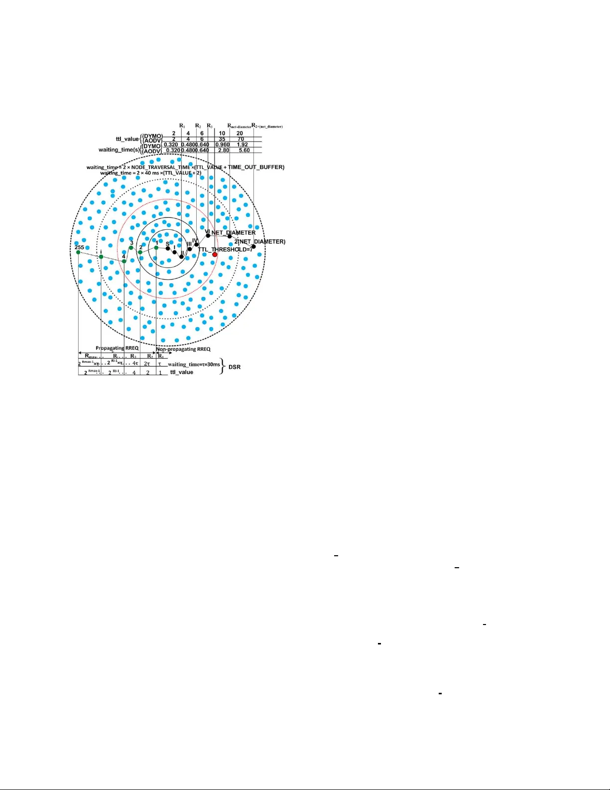
1 Modeling Routing Ov erhead Genera ted by W ireless Reacti ve Routing Protocols Nadeem Jav aid, A yesha Bibi, Akmal Jav aid, Shahzad A. Malik Department of Electrical Enginee ring, COMSA TS Institute of Information T echnology , 44000, Islamabad, Pakistan. nadeemjavaid@comsats.edu.pk Abstract —In this paper , we have modeled the routing o ver - head generated by three reacti ve routing p rotoco ls; Ad- hoc On-demand Distance V ector (AOD V), Dynamic Source Routing (DSR) and DYnamic MANET On-deman (D YMO). Routing perfo rmed by reactive protocols consists of two phases; route discov ery and route maintenance. T otal cost paid by a protocol fo r efficient routing is sum of the cost paid in the fo rm of energ y consumed and time spent. These protoc ols majorly focus o n the op timization performed b y ex pandin g ring sear ch algorithm to control the flooding generated by the mechani sm of blin d flooding. So, we hav e modeled the energy consumed and time spent per packet both for route discovery and route maintenance. The proposed framework is ev aluated in NS-2 t o compare perfo rmance of the chosen routing pro tocols. Index T erms —Routin g proto cols, expandin g ring sear ch, rout- ing ov erhead, AOD V , DSR, D YMO, route disco very , route main- tenance I . I N T R O D U C T I O N R ECENT era has seen the plenty of mobile n etworks due to the proliferatio n of wireless devices all aroun d. Specially , recent stud ies h av e main ly f ocused o n W ireless Multi-hop Networks (WMhNs). I n a WMhN, e very node can act b oth as a send er/receiver and as a r outer f or the nodes which ar e n ot in the same tr ansmission ra nge. T hese k ind o f networks allow a vast r ange of applicatio ns rang ing from a confere nce or a business meeting to the en vironm ents like a battlefield o r a natural d isaster scenario. Perf ormance of all WMhNs is majo rly depend ing on the rou ting pr otocols operating them . Routing p rotocols are of two ty pes with respect to their routing nature; reactive a nd pro activ e. Th e main difference between the two categories is based on the calcu lation of routes. Proacti ve proto cols perio dically perf orm rou ting table calculation indepe ndently from the data request arriv al; like DSD V [1], FSR [2], [3], OLSR [4], [5], etc. Reacti ve protocols calculate routes on r eaction of data request arrives; r ightly called ’on- demand ’ r outing p rotocols; e.g., A ODV [6 ], DSR [7], [8 ], TORA [9], D YMO [ 10], [11], etc. Reacti ve p rotocols are best suited f or th e networks with higher rates of mo bility and proactive o nes are design ed for dense and static networks. T o keep up-to-date all nodes ab out all links, reactive p rotocols have to deal with frequen t lin k breaks due to high mobilities. For this, reacti ve protoc ols exchange lot of contro l ( routing) packets increa sing routing overhead. In this pap er , we, therefor e, have modeled the routing overhead ge nerated by the above men tioned three reactive routing protocols. Th ey per form r oute discov ery ( R D ) and route maintenan ce ( RM ) o perations fo r ro uting. In the earlier p rocess, th e pro tocols find the route fo r de sired des- tination, while the for mer pr ocess starts a fter establishment of r outes; as, monito ring the active r outes and appr opriate actions to be taken after link br eakage detection . Expan ding Ring Search (ERS) algorith m and Binary Ex ponential Back- off (BEB) algo rithms ar e used by all of th e th ree pr otocols with d ifferent parameter s, as, shown in Fig.1. Gratuitous Route REPlies (Grat. RREPs) are used by DSR a nd A OD V during RD pro cess u nlike D YMO to reduce routing overhead. During rou te repair , DSR adop ts packet salv aging ( P S ) due to promiscuo us listening mode, while A OD V im plements local link repair ( L LR ) after link break detection. Rest of the paper is arra nged as follows: section II discusses related work and motiv ation. Sectio nIII and IV describe opti- mization of flooding using ERS algorith m. The detailed frame- work for routing operatio ns in reacti ve protoco ls is explaine d in sectionV . Mo reover , for testing th e propo sed fr amew ork in NS-2, sectionVI g i ves analytical simulation results. I I . R E L A T E D W O R K A N D M OT I V AT I O N In [12], authors make a survey about control overhead of ad - hoc routing pro tocols. They characterize reactive and pr oactiv e protoco ls as ”hello proto cols” and ”flo oding proto cols” and prove from simulations tha t mo re control pac kets are needed for hello protoco ls in mobile scenarios as compared to flooding protoco ls. Ther efore, hello pro tocols are mo re suitable fo r fixed scena rios and flo oding protoco ls are well suited for mobile situatio ns. Ho wev er, Jacq uet, P . et. al [12] only discu ss energy cost for routing p rotocols. While, we model b oth energy and time costs f or reactive pr otocols. Authors in [1 3] give an expression C ( r p ) total = C ( r p ) E × C ( r p ) T , for measurem ent of tota l cost; C ( r p ) total of a rou ting pr otocol which is the p roduct of energy cost; C ( r p ) E and time c ost; C ( r p ) T . While C ( r p ) E means energy consumed while C ( r p ) T is the time spent b y a protocol fo r routing operations; R D and R M . Authors compar e simple floo ding with ERS basic mechanism. Moreover , the overhead c ost is ev a luated as the total cost. Whereas, we further classify both time cost a nd energy cost for RD and R M . T herefor e, C ( r p ) E = C ( r p ) ( E − RD ) + C ( r p ) ( E − RM ) and C ( r p ) T = C ( r p ) ( T − RD ) + C ( r p ) ( T − RM ) are the respectiv e ene rgy and 2 time cost expressions f or a routing protocol in ou r framew ork. Moreover , we relate these costs not only with basic cost of ERS for A OD V , DSR and D YMO, but also we p resent improved equations for ERS. Fig. 1. E RS Algorithm used by A OD V , DSR, D YMO Lin, T . et. al [ 14] present an analytical model for co mparison of routing proto cols proposing a framew ork with o verhead as a metric. They compare the u se of relay nodes of p roactive pro- tocols with flood ing process of reacti ve p rotocols. Whereas, we consider time cost alon g with routing overhead an d also make intra-com parison model fo r reactive protoc ols by pr esenting separate models of r espectiv e flood ing mechanisms alo ng with the op timization strategies. Saleem et. al [15] improve th eir work in [16], b y taking inspiration from Broch, J. et. al [17 ] an d present flooding cost of rou ting p rotocols. They presen t a perf ormance evaluation framework th at can b e u sed to mo del two key p erforman ce metrics of an ad-ho c routing algorithm ; r outin g overhead and r oute optimality . They co mpare two me trics; total en - er gy con sumption and r oute discovery latency to evaluate the perfor mance of four promin ent ad- hoc ro uting algorithms; DSD V , DSR, A ODV -L L and G ossiping. Howe ver , they d o not specify any co st for RM proc ess fo r rea cti ve proto cols. They also do not mo del any of the supplem entary strategies o f routing pr otocols and expression for time co nsumption . While, we consider broad cast prob ability; P s equal to stochastic forwarding ; P r , in the same way as specified in [1 6]. W e not only mod el th e routing packet cost for A OD V , DSR and D YMO, but a lso time expenditure f or these protocols during their routin g operatio ns. Then we consider sup plementary strategies ( grat. RREP s , LLR and P S ) o f resp ecti ve proto cols to accu rately e valuate their routing costs. I I I . F L O O D I N G I N R E AC T I V E P R OT O C O L S A flooding a lgorithm is used for exchanging the topolog ical informa tion with every part of a network. I n flooding ea ch node can act b oth as a so urce and as a ro uter . E ach nod e broadc asts rou te in formatio n to all of its neighb ors u ntil destination is r eached. This repeated br oadcast results in the reception o f a particular message by all nod es in the network. A straig htforward approa ch for b roadcasting as flooding tech- nique is blind fl ooding ; each node is required to r ebroadca st the packet whenever it receives the packet f or the first time. Blind floodin g can cause the broa dcast storm problem by gener ating the redun dant transmissions. Each routing protoco l has to pay some cost for the routing overhead b ecause of flooding. In [1 6], autho rs present fo llow- ing equatio n. C p = P S d av g if h = 1 P S d av g + d av g h − 1 X i =1 ( P S ) i +1 i Y j =1 d f [ j ] other w ise (1) The number of d irectly connected or adjacent n eighbor nodes with in a network for a node is k nown as degr ee o f that node. An isolated nod e is a node which has zero d e gr ee . In eq.1, h is the number of hops, d avg is average degree of a node, d f [ j ] is th e expected fo rward degree of a no de at th e j th hop and is the a verage number of neighbor s of that nod e which forwards a received RREQ with probab ility of br oadcasting; P S [18]. I V . O P T I M I Z A T I O N O F F L O O D I N G U S I N G E R S A L G O R I T H M Eq.1 gi ves an approx imate cost paid by a protoco l per packet for R D u sing blin d flood ing . There are m any optimization s to control th e r outing overhead . E RS [19] is o ne of the optimization techniqu es and is a dopted b y A OD V , DSR and D YMO. In ERS, the flooding is con trolled by th e T ime T o Liv e (TTL) values to limit the b roadcast. As, ERS uses blind floodin g for broad casting, so? its routing cost ca n b e calcu lated fro m eq.1 . In the c ase of ERS, h is rep laced by the TTL value in a rin g. C E − R i is the cost of any ring; R i that generates RREP(s) an d the ring R i is called R r rep and it can disseminate up to the maximum limit R max limit resulting in either succ essful or unsuccessful RD ; i. e; R i \ R i ∈ R r rep ∨ R i ∈ R max limit . So, C E − R i can b e calculated as: C E − R i = P r d avg if T T L ( R i ) = 1 P r d avg + d avg T T L ( R i ) − 1 X T T L =1 ( P r ) T T L +1 T T L Y j =1 d f [ j ] otherwise (1 a ) { R i \ R i ∈ R i → R rr ep ∨ R i ∈ R i → R max limit } C E − RD = R max limit X R i =1 ( C E − R i ) R i if no RRE P receiv ed C E − R rr ep if T T L ( R rr ep ) = 1 R rr ep X R i =1 ( C E − R i ) R i otherwise { R rr ep = 1 , 2 , 3 , ...., max limit } (2) RD using ERS requ ires b roadcast inside the rings by incrementin g TTL values relati ve to the previous TTL value. In ERS, gr adual growth o f broadcastin g ring takes place to reduce the chan ces of flooding in the en tire n etwork that 3 results in f ormation of dif ferent number s o f rings fo r different broadc asting levels, as shown in Fig.1. The collective routin g cost of these expanding r ings during RD process C E − RD can be compu ted using eq.2. V . M O D E L I N G T H E C O S T PA I D B Y R E AC T I V E P ROT O C O L S A routing pr otocol, p has to pay so me cost in the form o f consumed energy per packet, C ( p ) E and in the fo rm of time spent p er packet, C ( p ) T to enc ounter the topolog ical chan ges during the varying number of nodes and traffic r ates. In [13], the autho rs have e xpressed this cost by th e following equation: C ( p ) total = C ( p ) E × C ( p ) T (3) A. Cost of Ener g y Consumption Each r eactiv e pr otocol, rp per forms RD and RM , so, un - like, eq.3, we define the cost to b e paid for energy consump tion during RD an d RM processes; C ( r p ) E : C ( r p ) E = C ( r p ) E − RD + C ( r p ) E − RM (4) C ( r p ) E is different for each reac ti ve protocol due to dif ferent routing strategies. The m ultiple r outes in Route Cache (RC) reduce the r outing overhea d with the help of grat. R REPs and PS in DSR. I n A ODV , rou te length is sho rtened by gr at. RREPs to r educe the cost o f RD process wh ile successful LLR probab ility; P LLR S av o ids the re- initiation of RD p rocess. Energy Consumed for RD A OD V , DSR and D YMO use ERS for RD by b roadcasting the RREQ messages from th e source no de. A sou rce node may re ceiv e RREPs from the nodes that contain alternate (short) ro ute for the d esired destina tion. T hese replies are only u sed in A OD V an d DSR and are kno wn as gr at. RR EPs . The destination RREPs ar e generated b y th e destination its elf (destination RREPs are g enerated in all the three r eacti ve protoco ls). Eq.5 gives the cost to be paid for RREQ p ackets as well as the cost for RREPs produced during R D . n r rep notation is used for n ode(s) generatin g the RREP from R r rep . C ( rp ) E − RD = R max limit X R i =1 ( C E − R i ) R i if no RRE P receiv ed C E − R rr ep + n rr ep X n =1 ( RRE P ) n if T T L ( R rr ep ) = 1 R rr ep X R i =1 ( C E − R i ) R i + n rr ep X n =1 ( RRE P ) n otherwise { R rr ep = 1 , 2 , 3 , ...., max limit } (5) The gener ation o f RREP(s) in A ODV and DSR is a lso due to the v alid rou tes in Routing T able ( R T ) or ( RC ) , so, R i for DSR and A OD V is less than D YMO, as, grat. RREPs ar e absent in D YMO. rr ep in R r rep can b e written as: rr ep = 1 , 2 , 3 , ...., max l imit . Whereas, d r rep represents RREP gen erated by destination . Energy Consumed for RM In RM p rocess, different p rotocols pay different costs for link monitoring and also there ar e d ifferent costs for different supplemen tary main tenance strate gies in case of link breakage; as, C E − LLR for A ODV , C E − P S for DSR, an d D YMO d oes not use any me chanism. Following equations giv e RM cost for three p rotocols: C ( AO D V ) E − RM = C E − l − mon + C E − LLR + n X z =0 ( RE RR ) z (6) C ( D S R ) E − RM = C E − P S + n X z =0 ( RE RR ) z (7) C ( D S R ) E − RM = n P S X k = n BL B ( RRE Q ) k + n X z =0 ( RE RR ) z (8) C ( D Y M O ) E − RM = C E − l − mon + n X z =0 ( RE RR ) z (9) Where, C E − l − mon is the link mon itoring cost paid by A OD V a nd D YM O in the form of HELLO messages and it is giv en in eq. 10. C E − l − mon = τ link − in − use τ H E LLO I N T E RV AL × N hops − in − r oute (10) Where, n B LB is the no de bef ore link break and n P S may be any n ode from source to n B LB . In wireless environment, there are freq uent link breaka ges that lead to link failures. As a resu lt, the ro utes becom e ineffecti ve. The link br eakage is detected by d ifferent protoco ls by different strategies. D YMO and A OD V generate HELLO m essages to check the c onnec- ti vity o f acti ve routes, while DSR gets the link le vel feedback from link lay er . Th is cost depend s upon the link tim e, i.e. a link in use (active link); τ link − in − use and length o f th e path in ho ps and the value of H E LLO I N T E RV AL constan t. Broadcast needs to sen d z number of RERRs d epending upon different situations for different protocols, as discussed be low . In D YMO , link breakag e causes th e br oadcasting of RERR messages. When the prob ability of successful fo r LLR ; be- comes zero then it lead s to th e dissemination of RERRs in A OD V . On the other han d, DSR piggybac ks RERR m essages along with next RREQs in th e case of route re-discovery pro cess, while these RERR messages are b roadcasted in the case o f success of P S . There are thr ee different scenarios fo r rea cti ve p rotocols describing the route repair mech anism after d etection of r oute failure because o f link br eakage. The mo st simple me chanism describes that R D r e-initiation process takes place u nder the limited retries co nstraint for rou te re-discovery pr ocess: RRE Q RE T R I E S = 3 in D YMO, RRE Q T RI E S = 2 in A OD V , an d M axM ainRexmt in DSR=2 retra nsmissions. In A OD V after unsuccessful RD and normally in D YMO, RERR messages are b roadcasted by the node wh ich detects any link br eak and route rediscovery process is started throu gh source n ode. Fig.2.a. clearly demonstra tes the impor tance of LLR in A OD V . If it becomes successful in a dense network then it saves th e en ergy con sumed during route re-discovery . On the oth er hand, if LL R becom es unsuccessful then energy 4 cost is increased by re-in itiating RD process a fter per forming LLR strategy , as depicted in Fig.2 .b . DSR’ s P S tec hnique can reduce both the energy and time cost to be paid by a r eactiv e p rotocol by diminishing the route re-discovery . In the case of su ccessful P S , RERR message s are broadcasted to neighbo rs for the deletion of useless routes. Whereas, the ab sence of alter nate route(s) in R C leads to the failure o f P S . I n this situation , RERR message s are to b e sent by piggyback ing t hem in the next RREQ m essages during route re-d iscovery process . Cost of LL R in A OD V is given by the following equation. C ( AODV ) E − LLR = P r d avg + d avg T T L ( R LLR ) − 1 X T T L =1 ( P r ) T T L +1 T T L Y j =1 d f [ j ] (11) Here, R LLR represents the ring th at limits LL R activity . TTL value for R LLR is calculated with LO C AL ADD T T L (= 2 ) and M I N RE P AI R T T L (it is last known h op-cou nt to the destination ). Th e per p acket cost of LLR ; C ( AOD V ) E − LLR depend s up on the TTL value of R LLR . I n large n etworks, successful LL R process is m ore useful, because the chances of route re-discovery can be reduced which utilizes mo re bandwid th space. T T L ( R LLR ) is obtained fro m the equatio n gi ven below: max ( M I N RE P AI R T T L, 0 . 5 × # hops ) + L OC AL ADD T T L (12) Where # hops is the num ber of hops to the sender of the currently undeliv erable data packet. Thus, local repair attempts will o ften be imperceptib le to the o riginating node, and will always have T T L > = M I N RE P AI R T T L + LO C AL ADD T T L . B. Cost of T ime Consumption The co st of end- to-end path calculation time C ( r p ) T in reactive pro tocols depend s upon C ( r p ) T − RD and C ( r p ) T − RM . C ( r p ) T = C ( r p ) T − RD + C ( r p ) T − RM (13) Time Consumed for RD by DSR τ is constant time initially used for non-p ropaga ting RREQ ( N onpr opReq u estT imeout ) and its value is 30 ms . R max limit is th e max imum ring size and it dep ends on the buf fer time as well as the maximu m allo wed broadcasting dur- ing pro pagating RREQ ( D iscov e ry H opLimit = 255 ) . The BEB is associated with each propaga ting r ing. The expression for Time Consumed for RD by DSR is giv en below . C ( D S R ) T − RD = τ if R r rep = 1 R max limit X R i =1 2 R i − 1 × τ if no RR E P r eceiv ed R rr ep X R i =1 2 R i − 1 × τ other w ise (14) Time Consumed for RD by A OD V a nd D YMO Both in A ODV and D YMO, firstly , T T L V ALU E in IP header is set to T T L S T AR T (=1 in the case of link laye r feedback otherwise =2) then it is increased by T T L I N C RE M E N T (= 2) up to T T L T H RE S H O L D (= 7) [6]. When T T L T H R E S H OLD is reached, T T L V ALU E is set to N E T D I AM E T E R ( for A OD V = 35 [6] a nd for D YMO = 10 [7]). For disseminatio n in the entire network, T T L S T ART and T T L I N C R E M E N T both are set to N E T D I AM E T E R . Moreover, maximum RREQ tries are 3 for D YMO [7] , and maximum retries are 2 for A ODV . The RRE Q T I M E is set to 2 × N E T T R AV E RS AL T I M E (whereas, N E T T RAV E RS AL T I M E = 2 × N OD E T RAV E RS AL T I M E × N E T D I AM E T E R ) . C ( AODV , DY M O ) T − RD = R max limit X R i =1 τ 1 ( T T L ( R i ) + τ 2 ) if no RRE P r eceiv ed R rr ep X R i =1 τ 1 ( T T L ( R i ) + τ 2 ) otherwise (14 a ) Where, τ 1 = 2 × N O D E T RAV E RS AL T I M E an d τ 2 = T I M E O U T B U F F E R . There are two possibilities for A ODV and D YMO; first is the case when R D p rocess becomes successfu l in threshold r ings R thereshold , wh ile in second case RD process needs to disseminate the request in the whole network; R netdiameter . For the se two rin gs, we define T T L ( R thr shold ) and T T L ( R netdiameter ) . Earlier represents the TTL value in a ring which gener ates RREP(s) inside R thereshold with T H RE S H O L D and later shows TTL vale for the entire n etwork; T T L ( R netdiameter ) with N E T D I M E T E R . Time Consumed for RM in A ODV A OD V starts LLR process after no ticing a lin k failure. C T − LLR giv es the time cost o f LLR that d epends upon the TTL value o f the ring; LL R ( R LLR ) . In the case o f LLR failure, A OD V disseminates RERR m essages. τ r ecv − RE RR represents the time wh ich is spen t to reach RERR m essage from the node detecting the link failur e to the or iginator node. C ( AOD V ) T − re − RD cost is to be paid to start r oute re-discovery b ased on the value RR E Q RE T R I E S (= 2) . C ( AO D V ) T − RM = A if LLR is succes sf ul B if LLR f ails, RRE Q RE T RI E S ex pir es C o ther w ise (15) where, A = R LLR X R i =1 τ 1 ( T T L ( R i ) + τ 2 ) B = R LLR X R i =1 τ 1 ( T T L ( R i ) + τ 2 ) + τ r ecv − RE RR C = R LLR X R i =1 τ 1 ( T T L ( R i ) + τ 2 ) + τ r ecv − RE RR + C T − re − RD C ( AOD V ) T − re − RD = C ( AOD V ) T − RD Time Consumed for RM in DSR After detecting a link failure, time τ P S is utilized to check alternative routes in RC of interm ediate no des (from a node which detects link failure to a nod e having alter nate r oute for this b roken link; n P S . This τ P S value is highe r; if nod e containing alterna ti ve route; n P S is near est to the node which detects link break age. In the case o f failure of P S or in the case of presence o f alternati ve rou te in R C of the o riginator 5 node, τ P S attains a maximu m v alue and is con sumed by all intermediate rem aining nod es in a ro ute (fro m a node that detects link b reak up to th e orig inator of this broken route) . C ( DS R ) T − RM = n P S X k = n BL B τ k ( P S ) if P S is s uccessf ul n orig X k = n BL B τ k ( P S ) + C ( DS R ) T − r e − RD otherwise (16) where, C ( DS R ) T − re − RD = C ( DS R ) T − RD , n B LB is the node just before link b reakage, a nd n or ig is the n ode which o riginates r oute discovery p rocess. Time Consumed for RM in D YMO A RERR message is bro adcasted by th e node th at detec ts link break . After a time τ r ecv − RE RR , which is consumed for receiving RERR message by the source n ode, sou rce n ode initiates RD ; C ( DY M O ) T − re − RD is based on RR E Q RE T R I E S (= 3) con straint. C ( DY M O ) T − RM = τ recv − RE RR if RREQ T RI ES expir es τ recv − RE RR + C ( DY M O ) T − r e − RD otherwise (17) Time-T rade-Of fs between PS and LLR In P S of DSR, check ing the R C of intermediate n odes for alternate route(s) consum es m ore time. In the case of successful P S , time ca n be red uced as compare d to time consump tion fo r route re-d iscovery from source for the end - to-end pa th calculation. On the other hand, P S che cking time adds-up with route re-discovery time in case of failure. Same is the case with LL R in A OD V . Success of the process lessens end-to -end path time because route re-rediscovery process is not initialized. While, LLR inc rease the path len gth in the case of unsuccessful repair, because the repa ir time is also added with r e-discovery time. As, LL R is per formed by broadc asting a small TTL value, so, R LLR consumes some time during rep air . The time cost of LLR in A OD V C ( AOD V ) T − LLR can be c alculated as: C ( AO D V ) T − LLR = LLR X R i =1 τ 1 ( T T L ( R i ) + τ 2 ) (18) V I . A N A LY T I C A L S I M U L A T I O N R E S U LT S C O R R E S P O N D I N G T O D E S I G N E D F R A M E W O R K W e ev aluate perf ormance of our mo deled fram ew ork in N S- 2. For simu lation setup, we ha ve chosen Continuous Bit Rate (CBR) traffic source s with a packet size of 5 12 bytes. The mobility mo del used is Random W ayp oint. W e propose three different scenarios: RREQ Time Interval No. of RREQ Packets 0 0.2 0.4 0.6 0 200 400 600 800 1000 (a) Control Ov erhead for 5 hops RREQ Time Interval No. of RREQ Packets 0 0.2 0.4 0.6 0 500 1000 1500 AODV DSR DYMO (b) Contro l Overhea d for 10 hops Fig. 2. Control Overhea d generated by react i ve protocols Scenario.1 Area for simulation is 80 0 m × 600 m . 5 0 nod es are moving with speed of 5 m/s for simulation time of 30 0s with 2s pause time. Scenar io.1, as dep icted in Fig.2, is per- formed by cou nting th e distance m easured by routing protoco ls in hops to con struct appropriate p ath. As, wireless nod es also behave as rou ters for the n odes wh ich a re not in the same transmission range , it is mor e appropr iate to count the distance in hops. Pause Time in sec E2ED 0 100 200 300 400 0 0.02 0.04 0.06 0.08 0.1 0.12 AODV DSR DYMO (a) E2ED for higher mobiliti es Pause Time in sec E2ED 500 600 700 800 900 0 0.05 0.1 0.15 0.2 (b) E2ED for lower mobilities Pause Time in sec NRL 0 100 200 300 400 0 1 2 3 4 5 (c) NRL for higher mobilit ies Pause Time in sec NRL 500 600 700 800 900 0 1 2 3 4 5 (d) NRL for lowe r mobilities Fig. 3. S imulat ion results for scen ario.2 for v arying mobil ities Scenario.2 Sim ulation results for scenario. 2 are shown in Fig.3. The area specified is 1000 m × 1000 m field presenting a squar e space to allow 50 m obile nod es to m ove inside. All of the n odes ar e provided with wire less links of a bandw idth of 2M bps to tr ansmit on. Simulations are ru n for 900 seconds each. Each packet starts its journey from a random lo cation and moves towards a random destinatio n with the chosen speed o f 15m/s. The 20 source-destina tion pairs are spread random ly in the network. Once the destination is reached, another r andom destination is targeted afte r a specified pause time (f rom 0s to 900 s). A particu lar scenario for a par ticular pause time is run for five times and mean of the five obta ined values for a particular perfo rmance parameter is used to plot the gr aphs. No. of nodes E2ED 10 20 30 40 50 0 0.1 0.2 0.3 0.4 0.5 (a) E2ED for lo wer scalabi lities No. of nodes E2ED 60 70 80 90 100 0 0.2 0.4 0.6 0.8 (b) E2ED for higher scala biliti es No. of nodes NRL 10 20 30 40 50 0 2 4 6 8 AODV DSR DYMO (c) NRL for lowe r scalabil ities No. of nodes NRL 60 70 80 90 100 0 2 4 6 8 10 12 14 (d) NRL for higher scalab ilitie s Fig. 4. S imulat ion results for scen ario.3 for v arying scal abilit ies Scenario.3 All of th e par ameters for Scenario .3 are the same as that of Scenar io.2, except a constan t p ause time o f 2s and different scalabilities varying from 10 to 1 00 nod es. Simulation results are represented in Fig.4. W e have ev aluated and com pared the pro tocols by three perfor mance parameter s; No. of RREQ Packets, A verage End- to-end Delay (E2 ED), and Norma lized Routing Load (NRL) . 6 No. of RREQ Packets in scenario.1. D YMO generates the highest num ber of RREQ packets a gainst all RREQ tim e intervals among all three reactive protocols. T his is beca use of absence of grat. R REPs unlike A OD V and DSR. Besides this, any oth er supplem entary routin g strategy like P S and L LR is also a bsent in D YMO. The RREQ retries in D YMO are 3 which is the high est v alue of rediscovery retries as compared to A OD V and DSR. The prom iscuous listening mode of DSR not on ly helps in R D proce ss by shortening the r outes thro ugh grat. RREPs , but also h elps to reduce routing overhead in RM process through P S . Therefore, DSR produ ces less number o f RREQ packets bo th in 5 h ops and 10 hop s in Fig.2. E2ED in scenario.2. As demonstrate d in Fig.3. a,b, A O D V among reactive pr otocols attains the highe st d elay . Because, high dynamical situation s result in frequent link breakag e, and LLR op eration for RM som etimes results in increased pa th lengths. D YMO pro duces the lowest E2ED am ong reactive protoco ls b ecause it o nly uses the ERS for route finding with- out any supplementary o ptimization mechanism; as che cking RC in DSR and R T in A OD V before RD thro ugh ERS attains some delay . The reason for consum ing more time for end -to- end path establishment in DSR is th at for R D it first search es the d esired rou te in RC and then starts RD , if the sear ch fails. NRL in scenar io.2. Due to the absence of grat. RREPs , (Fig.3.c,d) D YMO p roduces higher rou ting ov erhead. Whereas, DSR, due to the promiscuou s listening m ode shows the lowest routing load . Altho ugh, A ODV uses grat. RREP s but due to the use of HELLO m essages like D YMO and LLR , it causes more rou ting load than DSR. During higher mobilities, (i. e., at lo w Pause times), the rate of link break age also increase. In response to this link breakage, all o f the on- demand protoco ls disseminate RERR message to inform the RREQ generator ab out the faulty links and prevent the u se of in valid r outes. As a r esult increa sed routing overhead occurs. E2ED in scenario.3 . The grat. RREPs produce diverse effects in different no de density scenarios. D YMO d oes no t use this strategy; the ab sence of the m echanism keeps the lowest E2ED of D YMO in all scalabilities. First checkin g the RC instead of simple E RS based RD p rocess augm ents the delay when pop ulation of nodes increases, thus mor e delay DSR pr oduces which is pr esented in Fig.4. a,b ., a s compare d to D YMO. A ODV experien ces th e high est E2 ED in all scala bilities due to L L R pro cess. NRL in scenario. 3. NRL of D YMO is lowest wh ereas, the highest one is genera ted by A ODV in all network flows by varying nu mber of nodes, as obvious fr om Fig.4.c,d. The HELLO messages to check co nnectivity of active routes, LLR and grat. RREPs increase the gener ation of contr ol pa ckets. Whereas, DSR along with promiscuous listenin g mode reduces the routin g overhead as compar ed to A ODV . Eac h node participating in RD pro cess (inc luding in termediate n odes) of DSR, learns the routes to othe r n odes on the ro ute. P S technique is used to get routes from RC of i nterme diate nodes. This strategy is used to quick ly access and to solve broken link issues by pr oviding alternati ve route. V I I . C O N C L U S I O N A N D F U T U R E W O R K In th is work, we have modeled the cost p aid by 3 reactive protoco ls; A OD V , DSR, and D YMO for the g enerated routing overhead to keep the topological inf ormation u pdated amo ng wireless node s. The cost co nsists of the en ergy consumed and time spent p er packet for ro ute d iscovery and ro ute m ain- tenance process. In creased ro uting overhea d and inc reased delay ar e major issues to be reso lved by the routing pro tocols in wireless en viron ment, so, are c onsidered in this work. Optimizations like P S and LLR of retransmission s result better p erform ance of a pro tocol. While the reductio n of network band width utilization is more u seful when data flows are increased . In future, we are interested to re -implement these reacti ve p rotocols with ne w routing link metric; IBETX (Interfe rence a nd Bandwidth Adjusted Ex pected T ransmission Count) [20] a nd In verse ETX [21]. B ecause, these metrics h av e achieved re duced overhead by a proactive protoco l Dest ination Sequenced Distance V ector (DSDV). R E F E R E N C E S [1] C. E. Perkins and P . Bhagwat, ”Hi ghly dynamic D estina tion-Seque nced Distance - V ector routing (DSDV) for mobile computers, ” SIGCOMM Comput. Commun. Rev ., v ol. 24, pp. 234-244, 1994. [2] M. Gerla, et al. , IETF Draft-01, ”Fisheye State Routing Protocol (FSR) for Ad Hoc Network s”, 2000. [3] G. P ei, et al. , ”Fishe ye State Routing in Mobile Ad Hoc Networks, ” in ICDCS W ork- shop on Wire less Netwo rks and Mobile Computing, 2000, pp. D71-D78. [4] T . Clausen and P . Jacquet, IETF RFC-3626, ”Optimized Link State Routing Protocol OLSR, ” The Internet Society http:// www . ietf. org/r fc/rfc3626. txt, 2003. [5] T . Clausen and P . Jacquet, ”Optimized L ink State Routing Protocol (OLSR), ” ed, 2003. [6] C. Perkins, et al. IETF RFC3561, ”Ad hoc On-Demand Distance V ector (A ODV) Routing”. A va ilable: http://www .ietf.org /rfc/rfc35 61.txt [7] D. Johnson, et al. , IETF RFC, ”The Dynamic Source Rout ing Protocol (DSR) for Mobile Ad Hoc Networks for IPv4”, ” 2007. [8] D. Johnson, et al. , ”DSR: The Dynamic Source Rout ing Protocol for Multi-Hop W ire- less Ad Hoc Networks, ” in Ad Hoc Netw orking, by Charles E. Perkins, 2001. [9] V incen t D. Park and M. Scott Corson. T emporally-Orde red Routing Algorith m (TORA) v ersion 1: Functional s pecific ation. Intern et-Draft, draft-ie tf-manet-t ora-spec-00.txt, Nove mber 1997. [10] I. Chake res and C. E. Perkins, IETF Draft dymo-05, ”Dynamic MANET On-demand (D YMO) Rout ing”, ” 200 6. [11] R. E. T horup, ” Implementing and Evalua ting the D YMO Routing Protocol ”,Master T hesis, 2007. [12] Jacquet, P . and V iennot, L., ”Overhead in mobile ad-hoc netwo rk protocol s”, RAPPOR T DE RECHERCHE-INSTITUT NA TIONAL DE RECHERCHE EN INFORMA TIQUE ET EN A UTOMA TIQUE, 2000. [13] Park, I. and Pu, I., ”Ener gy Ef ficient Expanding Ring Search ”, p-198- 199, 2007. [14] Lin, T . et al. , ”A framew ork for wireless ad hoc routing protocols, lin2003f ramew ork”, 1162-1167, 2003. [15] Saleem, M. et al. , ”On performanc e modeling of ad hoc rout ing proto- cols”, EURASIP Journal on Wi reless Communications and Networking, 2010. [16] Saleem, M. et al. , ” A formal performance model ing framewo rk for bio- inspired ad hoc routing prot ocols ”, p-103-11 0, 2008. [17] Broch, J. et al. , ”A performanc e comparison of m ulti-h op wireless ad hoc net work routin g protocols”, p-85-97, 1998 [18] Santi v anez, C.A. et al. , ” On the scalabili ty of ad hoc routing protocols ”,santi vanez2 002scalability , p-1688-1697, 2002. [19] Castaneda , R. et al. , ”Query localizati on techni ques for on-demand routing protocol s in ad hoc networks” 137-151, Wi reless Network s, 2002. [20] Jav aid, N. et al. , ”Interfer ence and Bandwidth Adjusted ETX in Wirel ess Multi-ho p Networks”, USA, G lobec om2010. [21] Jav aid, N. et al. , ”Iden tifying Design Requ irements for W ireless Roiuting Link Metri cs”, USA, Globeco m2011.
Original Paper
Loading high-quality paper...
Comments & Academic Discussion
Loading comments...
Leave a Comment