Multi-Modal Local Sensing and Communication for Collective Underwater Systems
This paper is devoted to local sensing and communication for collective underwater systems used in networked and swarm modes. It is demonstrated that a specific combination of modal and sub-modal communication, used simultaneously for robot-robot and…
Authors: Serge Kernbach, Tobias Dipper, Donny Sutantyo
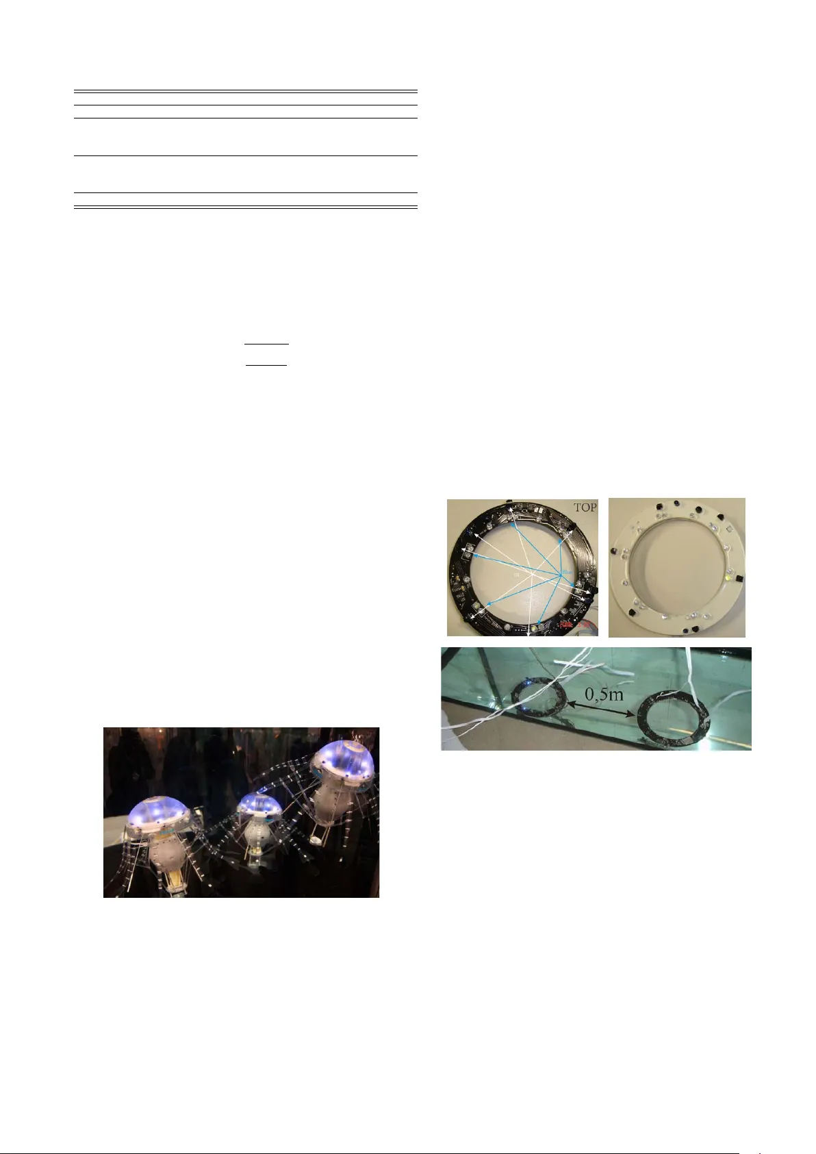
Multi-Modal Local Sensing and Communication f or Collectiv e Underwater Systems Serge K ernbach, T obias Dipper, Donny Sutantyo Abstract — This paper is devoted to local sensing and com- munication f or collectiv e underwater systems used in net- worked and swarm modes. It is demonstrated that a specific combination of modal and sub-modal communication, used simultaneously for r obot-robot and r obot-object detection, can create a dedicated cooperation between multiple A UVs. These technologies, platf orms and experiments ar e shortly described, and allow us to make a conclusion about useful combinations of different signaling approaches for collectiv e underwater systems. I . I N T R O D U C T I O N Underwater exploration represents a very important eco- nomic, technologic and scientific challenge. This is closely related to Arctic and Antarctic offshore resources, pollu- tion monitoring, general oceanographic data collection and, recently , to underwater actuation [1]. Due to very large underwater areas and high damping properties of water , application of multiple Autonomous Underwater V ehicles (A UVs) in cooperati ve missions seems very promising [2]. For application of A UVs in networked or swarm mode, there is a number of crucial issues: underwater sensing and communication (S&C), cooperation and mission control, design of A UV platforms, autonomous behavior and se veral collectiv e aspects of running multiple A UVs. In this work we concentrate on minimalistic local S&C [3], and related coordination strategies, being motiv ated by the follo wing reasons [4]. In se veral past and running projects de voted to underwater swarms, such as AquaJelly [5], Angels [6], CoCoRo [7], a number of A UV platforms and sensing technologies has been dev eloped. These works indicated two important issues: a successful A UV platform needs a dedicated combination of different S&C technologies, moreover capabilities of underwater cooperation depends on the lev el of embodiment [8] of on-board S&C systems. In several cases, e ven a simple multi-modal signal system leads to adv anced cooperation [9] (see e.g. the case of multi-agent cooperation [10]). Since swarm approaches rely primarily on local interac- tions between A UVs [11], the paper is dev oted to local S&C systems (unmodulated and modulated IR/blue light, RF and electric field), which can be used for robot-robot/robot- object detection and provide sub-modal information, such as direction and distances, as well as can be used for analog and digital communication [12]. These systems, de veloped for Institute of Parallel and Distributed Systems, Uni versity of Stuttgart, Univ ersit ¨ atstr . 38, 70569 Stuttgart, Germany , emails { Serge.K ernbach, T o- bias.Dipper , Donny .Sutantyo } @ipvs.uni-stuttgart.de, pre-print version, pub- lished in Proceedings of the 11th International Conference on Mobile Robots and Competitions, Robotica 2011, Lisbon, pp.96-101 each of the platforms is described in Sec. III, whereas Sec. II provides general overvie w over different S&C technologies. In Sec. IV we shortly sketch a few behavioral experiments with these systems and finally in Sec. V conclude about useful combinations of S&C and their embodiment for collectiv e underwater systems. I I . C O M PA R I S O N O F D I FF E R E N T S & C S Y S T E M S In this section we giv e a short overvie w o ver different state-of-the-art S&C systems in an underwater en vironment, see e.g. [13]-[14]. Four systems will be compared: • Sonar : Sonic wav es travel very well under water and the energy and build-space required for generating and receiving them is very lo w . This approach is used in so-called acoustic modems [15]. Drawbacks of this approach are, firstly , the relatively low sound trav el speed of roughly 1500 m / s (much slower than any other S&C system), and, secondly , multiple reflections causing essential distortions in the signal. • Radio : Electromagnetic wa ves are a standard communi- cation method in air; its application under water creates sev eral problems [16]. Due to water connectivity , the attenuation of radio w aves depends on the used fre- quency , which in turn results in the size of antenna. High frequencies ( > 100 MHz) only need a small antenna ( 0 . 1 m) while their range is restricted to 2 . 5 m. Lower frequencies (100 kHz) hav e a long range (100 m), b ut need a large antenna (100 m). • Optical : Using light as a communication channel can provide a compact size of transmitting equipment and acceptable range [14]. Due to the color dependent attenuation of light in water , the communication range varies between a few centimeters in IR spectra and increases to over a meter by using blue or green light. • Electric F ield : This is a new communication approach. It bases upon generating and measuring electric fields. The build-size and energy required for this system is very small. Unfortunately the attenuation of electric fields is v ery high, liming the range of this commu- nication channel to less than 1 m. W e will discuss this approach in Sec. IV -B. T able I shows an overvie w of the discussed approaches. Since the used A UVs operate in a swarm mode [17] (large number of A UVs, full decentralization, utilization of swarm approaches for coordination [18], application of evolutionary approaches [19], [20]), in this paper we concentrate on a local S&C approaches. The S&C is defined as local, when the communication range R c (i.e. communication v olume Channel Attenuation Antenna Size Range Sonar (30 kHz) 0.3 dB/m 0.1 m 300 m Radio (100 kHz) 1 dB/m 100 m 100 m Radio (1 MHz) 4 dB/m 10 m 25 m Radio (100 MHz) 40 dB/m 0.1 m 2.5 m Optical unmodul. (IR 800 nm) 10 dB/m 0.1 m 0.25 m Opt. modul. (PCM IR 800 nm) 10 dB/m 0.1 m 0.5 m Optical modul. (blue 460 nm) 1 dB/m 0.1 m 1.2 m Electric Field (2.5 kHz) 100 dB/m 0.1 m 1 m T ABLE I C O MPA R IS O N O F D I FFE R E NT C O M MU N I C A T IO N C H A N NE L S V c = 4 / 3 π R 3 c ) does not overstep the second-next-neighbors at a verage swarm density D sw = N /V sw , where V sw is the volume occupied by A UVs and N is their number . Local communication range R c can be approximated by R c = 3 s V sw N 4 / 3 π , (1) where for V sw = 5 m 3 and N = 20 , R c is about 0,4m. F or the platform size 10-15cm, this results in 3 to 4 times the robot length. Generalizing the A UV size up to 50cm, we assume that R l c within 0,5-1,2m are local, whereas R g c capable to cov er the whole V sw , i.e. 3-4m, are global. In the follo wing sections we consider the de veloped optical and electric field S&C approaches which are related to R l c . I I I . L O C A L S & R A P P RO AC H E S A. Multi-modal Optical System As the first developed approach for combined S&C within R l c , we describe a specific bi-modal directional optical system, which underlies cooperativ e behavior of AquaJelly robots [5]. AquaJelly was a project between Festo AG & Co. KG (coordinator and founder), Effekt-T echnik GmbH, and Univ ersity of Stuttgart intended to create a swarm ( N = 20 − 30 robots) of autonomous underwater robots, capable of multi-modal interactions and underwater recharging. Robots hav e been dev eloped and manufactured within a very short time of 8 months in 2007-2008. Fig. 1. AquaJelly robots. T echnical requirements define robot-robot, robot-docking- station, and collisions recognition; cooperati ve collision av oidance; sev eral types of cooperativ e behavior around docking station, and vertical movement of robots (robots possess only vertical DoF with a balancing mechanism; this allows an inclined vertical mov ement). Due to visual effects, which are one of the main dev elopmental goals of this platform, it was decided to use unmodulated blue light. Since sev eral communication approaches should remain invisible for human observers and to make the system more stable to different illumination conditions, it w as decided to use additionally 36kHz modulated IR light. The platform pos- sesses also very sensitive pressure and temperature sensors, 3D accelerometer and energy sensor (additional RF system was used for a backup communication with the host). The energy part consisted of 4A/h LiPo accumulator with a power management circuitry and Hot-Swap controller for underwater rechar ging. Due to low energy consumption, the autonomy lies between sev eral hours and with autonomous recharging is theoretically unlimited. 3D omni-directional communication and sensing was one of the main technical requirements. Blue light and IR sensors are used in different ways. Since IR light is more dumped in water , IR channels are very useful for a short range directional communication. Blue light channels are used as unidirectional system, which was mainly used for navigation approaches based on optical pheromone in the improv ed ver - sion of the platform. T o enable directional communication, the original platform has 11 IR emitters and receivers with integrated PCM decoder , see Fig. 2. Fig. 2. (T op-left) Placement of IR and blue light LEDs in the top of the ring; (T op-righ) Molded ring in white polyurethane; (Bottom) Experimental measurement for IR communication/sensing. Spatial displacement has an important role, so sidewise IR emitters and recei vers are set up each 60 degrees and separated through thick a black-colored PCB on T OP and BO TTOM sides. Three IR sensors are positioned do wn-side and two up-side. Six blue light LEDs are installed on the top of the platform and through mate cover created almost a homogeneous ”light ball” around the robot. All 17 commu- nication channels are independent from each other through an analog multiplexor . T o make the platform waterproof, the ring with all sensors was molded in polyurethane. Blue light system has been used in analog mode, whereas IR used a digital PCM-modulated signal. All sensors are directly connected to I/O pins of the Atmel MCU, which can pro vide around 8-10mA current at 3V , opening angle of all LEDs is about 10 degrees. Communication range of modulated IR is about 0,5m, see Fig. 2. Due to passive PCM filter , the communication range was fixed on this distance and used in 4kbps communication mode. A v erage range of the analog blue light system is about 1-1,3m and can be varied by regulating intensity and number of LEDs. The main idea for using two different optical systems was a split between analog gradient-based interactions between robots (visible for human observer) and digital channels used for robot-objects interactions and for communication, which synchronizes internal states of robots and docking sta- tion (invisible for observers). Thus, a combination between analog omni-directional ”long-range” and digital directional ”short-range” optical systems used in different modifications AquaJelly robots allowed a wide range of dif ferent sensing and communication approaches, which result in interesting cooperativ e behavior of these platforms, see Sec. IV. B. Modulated and Encoded Blue Light As a further dev elopment of the S&C system, described in the previous section, we intend to use only one light system with modulated blue light for both robot-robot/object detection, distance measurement and digital communication. Digital optical communication is widely used due to its high bandwidth. Howe ver , the absence of gradient-based optical guide for sensing and localization makes the digital system less suitable for navigation purposes. Therefore spe- cific protocols are required to extract sub-modal information about distances and orientation from the digital channel. The table II shows our underwater measurement results that compare the common modulated IR and blue light communication in many modulation types at the bandwidth of 119kbps. Modulation T ransducer Maximum Communication/Sensing direct Infra-red - / - IrD A Infra-red 7 cm / 0-5 cm TV Remote Infra-red 5 cm / 0-5 cm QAM Infra-red 12 cm / 0-5 cm direct Blue LED 20 cm / - / - IrD A Blue LED 60 cm / 0-5 cm TV Remote Blue LED 45 cm / 3-8 cm QAM Blue LED 120 cm / 7-12 cm T ABLE II R A NG E O F U N DE RWA T ER O P T IC A L C O M MU N I C A T IO N F O R 1 19 K B P S . As a digital communication transcei ver , the blue light system needs modulator , amplifier, signal conditioner, and protocol encoder/decoder . The one chip solution can be solved by using a CS 8130 IrD A chip from Cirrus Logic. Since the blue light system has a directional S&C, two chan- nels are not sufficient for the swarm robot to communicate in ev ery direction. The half duplex behavior of each channel makes one channel unable to be applied for sensing, because the sensing mechanism requires to transmit and to receive the sensing signal in one time. Therefore, the position of the transmitter and receiv er are swapped with neighboring channels for sensing application. The system must be configured and calibrated for finding the best modulation type for underwater communication and sensing. According to the measurement results, both for communication and sensing, the Quadrature Amplitude Modulation (QAM) seems to be the best modulation for underwater application. Fig. 3(a) shows the relation between (a) (b) Fig. 3. (a) Distance measurement with QAM blue light; (b) Active Sensing Algorithm. current sensitivity and communication distance. By using this curve, an active sensing algorithm can be added to the inter-robot communication algorithm by varying the ampli- fication and the sensitivity of the programmable amplifier via software, see Fig. 3(b). The robot can approximate the distance with other robots by gradually decreasing the current sensiti vity while communicating each other . The dev eloped inter -robot communication algorithm has three phases. First, when two robots are in the communication range, they be gin to establish the communication by sending their IDs to each other . Second, the communicating robots are approximating their distance by gradually decreasing the current sensitivity within the programmable gain amplifier . Therefore, after knowing their own position, behavioral or cooperation phased can be performed. A robot will continu- ously iterate the first phase if there is no other robots in the communication range. Hence an obstacle might reflect the transmitted signal and the robot would receive back the first phase communication packet that contains its own ID. C. Electric Sense After experimenting with optical S&C systems, we im- plemented another approach, which is inspired by weakly electric fish. These animals are capable of producing an electric field which they can use for localisation and commu- nication [6]. Here we try to use this bio-inspired approach for analog communication and navigation in robot swarms. Electric fields. Electric charges generate electrical fields in their vicinity . Electric fields are vector fields. For a point charge Q the field intensity ~ E can be calculated at each point ~ r as ~ E = Q 4 π 0 r · ~ r r 3 (2) with the permittivities 0 (vacuum) and r (relativ) [21]. The field vectors of multiple point charges follow the superposition principle. In our robot the electric field is gen- erated by a dipole. The field intensity is proportional to the charge in the electrodes, which themselves are proportional to the applied v oltage to the electrodes: Q = C · U (3) with the voltage U and the capacity C . Communication. The intensity of an electric field can then be detected by measuring the differential potential between two electrodes in the field. This potential is propor - tional to the electric field intensity , which itself is propor- tional to the output voltage of the sender . By modulating the output voltage of the sender , information can be transmitted. Localization. By using multiple pairs of electrodes in the receiv er it is possible to calculate the bearing and distance to the sender . This is achiev ed by utilizing the drop in field intensity with relation to the distance. A sinus w av e is impressed on the sender’ s electrodes which creates an oscillating electrical field. The field intensity depends mainly on the amplitude and frequency of the output voltage and some en vironmental conditions. The amplitude in the field intensity at a specific point ~ r is proportional to the amplitude of the output v oltage: u ( t ) = a o · sin( ω t ) ∼ E ( t ) ∼ a i · sin( ω t ) · ~ r r 3 (4) with the amplitude of the output signal a o and measured input a i , the frequency ω and the time t . If sender and receiver are approximately in the same plane and the electrodes hav e the same orientation (compare Fig. 4 left) (4) can be simplified to: a o · sin( ω t ) = a i · sin( ω t ) · F ( ω ) r 2 (5) with the frequency dependent proportionality factor F ( ω ) and the distance r between sender and receiv er . Measuring the sinus amplitude ( a 1 , a 2 , a 3 , a 4 ) at four points with a specific geometrical pattern (Fig. 4 right) leads to the following equations: a 1 = A o F ( ω ) · 1 ( r − s · cos α ) 2 , a 2 = A o F ( ω ) · 1 ( r − s · sin α ) 2 a 3 = A o F ( ω ) · 1 ( r + s · cos α ) 2 , a 4 = A o F ( ω ) · 1 ( r + s · sin α ) 2 (6) sender receiver 1 2 3 4 s r x y a Fig. 4. Position and orientation of sender and receiv er electrodes, top-(left) and side-vie w (right) In setting up these equations it is assumed that r >> s so that the error in the angle α and distance r between the different sensors is minimal. In (6) the proportional factor and output amplitude can be eliminated, under the condition of r > s leading to: r = s · cos α p a 1 /a 3 + 1 p a 1 /a 3 − 1 | {z } u 1 , r = s · sin α p a 2 /a 4 + 1 p a 2 /a 4 − 1 | {z } u 2 (7) and α = arctan u 1 u 2 (8) Design limitations. This approach has two design limita- tions: it requires the sender and recei ver electrodes to have the same orientation (i.e. vertical) and to be roughly in the same plane (horizontal to the orientation): • The first limitation holds no practical difficulties. Our robot maintains a specific orientation, caused by its center of gravity . By placing one of the sender and receiv er electrodes on top and one on the bottom of the robot the orientation is always vertical. • The deri vation above is only correct if sender and receiv er are on the same plane, which is horizontal to the orientation of their electrodes. In a three dimensional en vironment this is not always true, but usually the working space is wider than it is high, e ven in a 3D en vironment. Even so, we are working on overcoming these limitations. W e are confident that the second can be eliminated by rearranging the recei ver electrodes. T o ov ercome the first limitation additional electrodes may be needed. I V . E X P E R I M E N T S As described in the previous sections, dif ferent local S&C systems utilize the same hardware components for sensing and communication. Moreov er , they use modal and sub- modal approaches, which provide not only message trans- mission, but also deliv er spatial information about position and distances of robots and objects. In this section we de- scribe several beha vioral experiments, performed with these systems. A. Experiments with Bi-modal Optical System One of the implemented scenarios with AquaJelly robots had the following form, see Fig. 5. In water , a robot sends sequentially in all IR channels its own ID. Listening and sending times are selected as approx. 95% listening and 5% sending, so that all robots most of time silently observe the en vironment. Recei ving another-than-own ID means meeting another robot, whereas non-ID IR light means o wn reflection from passive objects. Granularity of IR channels is enough for rough collision av oidance with objects, e.g. walls of the aquarium. Collision av oidance based on digital channels are impossible for more than two robots (or robot and object). In opposite, blue light channels emit almost all time. Fig. 5. Experiment with collecti ve decision making during the docking approach. Since light has additi ve properties, when two robots meet each other, intensity of light in the point of light-spheres- intersection creates a light gradient and can be locally sensed by both robots. Especially interesting is the light gradient when se veral robots meet each other; they create complex gradients, which can be used for precise multi-robot navigation. Unfortunately , blue-light sensors continuously receiv e signals from their o wn light sphere so that no ef ficient communication is possible in this mode. Initially all robots are fully charged. When a robot has a low energy value, it swims up and rechar ges. With the progress of experiment, more and more robots swim up for recharging. In this way , se veral robots meet in the upper part of the aquarium and compete for the docking station, see Fig. 5(from left to right). Since only a robot with lowest energy value should recharge, all robots bilaterally exchange values of their own energy lev el. The robot with the lowest energy value can swim up. This local behavior leads to the following interesting collectiv e behavior . Due to light gradient created by many robots, all robots ex ert “optical pressure” on each other, and collecti vely swim down, whereas only one most ”hungry” robot swims up and recharges, see Fig. 5(right). B. Experiment with Encoded Blue Light In order to inv estigate the modulated blue light S&C system, we used underwater submarine toy as a mechanical platform with new electronic components for locomotion, computational and S&C capabilities. This submarine has three degrees of freedom and three actuators for moving for- ward/backward, turning left/right, and di ving up to 1 meter . The necessary modifications of the submarine including the replacement of the original electronic parts with the ne w designed electronic boards, and drilling some new holes on the robot’ s body for communication/sensing transducers placements. Cortex3 LM3S316 microcontroller with 25MHz of clock frequency , 16kb of internal flash ROM, and 16kb of RAM has been used in the platform. T w o motor drivers and two na vigational sensors are placed on the main board of the electronic platform. The combination of the av ailable PWM output from Cortex3 and motor dri ver perform the ability to control the swimming velocity via software. A digital compass and pressure sensor are added as a three- dimensional orientation sensor (an lo w-frequency RF part is foreseen for a backup communication with host). Fig. 6. (Left) Autonomously swimming A UV recognizes obstacles with the digital S&C system (active sensing); (Right) Experiments with digital communication. During the experiment, robot is deployed into the aquar - ium fulfilled with sev eral obstacles. The av ailable obstacles and aquarium’ s walls are used to examine the sensing capa- bility , see Fig. 6(left). Both types of obstacles have different type of optical characteristic, which create dif ferent reflection behavior for the blue light. Therefore, white papers can be put outside the aquarium walls to increase the reflection capability of the optical sensor . For testing the communication and acti ve sensing ca- pabilities, one robot is deployed underwater and a static encoded blue light transceiv er is installed on the aquarium wall as a measurement reference point, see Fig. 6(right). The static transceiver can illuminate se veral type of light signals if it recei ves a specific blue light pack et data from the swimming robot. Different types of blinking signals are used to examine the functionality of the activ e sensing capability . This approach underlies sev eral other experiments, where a fe w passiv e robots are identified by one activ e A UV as foraging targets. C. Experiment with Electric Field The circuit for electric field communication is very simple. It consists mainly of a digital-analog-con v erter (DA C) for the sender and four amplifiers (OP) with analog-digital- con verters (ADC) for the recei ver (Fig. 7). • Sender: The output of the 14-bit D A C is directly tied to one of the sender electrodes while the other is connected to VCC/2. The electrodes are in direct contact with the surrounding water . The output of the DA C can be set to a voltage between GND and VCC. This setup allows control of the field intensity and polarity . • Receiver: The recei ver has four pairs of electrodes in the water to measure the difference in the potential of the electric field in four places. The electrodes use capacitors as highpass-filters to filter DC signals. The signals are amplified by differential OPs (magnitude 1000) and digitized by 14-bit ADCs. For the experiments the sender and receiver are put under water (Fig. 4 right). The recei ver has a sampling rate of 10 kHz. The measured data is transmitted to a PC, where the bearing and distance are calculated. Fig. 7. Experiment electric field: test circuit, video stream, calculated bearing In the experiment the sender was moved around the receiv er and the received data was recorded together with a video tape of the experiment for comparison (Fig. 7). The true bearing was extracted from the video stream and compared with the from the electrical sensor data calculated bearing. Fig. 8 sho ws the result. For 50% of the measuring points the error is less than 5 ◦ and it exceeds never more than 15 ◦ . This might be further improv ed by increasing the magnitude of the amplifiers and reducing the noise through optimized circuits and digital filters. 0 5 10 15 20 25 30 35 40 45 0 50 100 150 200 250 300 350 400 measuring point angle (°) video stream electric sensor Fig. 8. Calculated bearing from data provided by (a) video stream and (b) electrical sensor V . C O N C L U S I O N In this work we considered se veral optical and electric- field-based approaches for sensing and communication within R l c . T ogether with S&C approaches for R g c , such as acoustic and low-frequency RF , they represent the av ailable spectra of S&C technologies for underwater networked and swarm robotics. As indicated in the Sec. IV and from other performed experiments, these approaches combine commu- nication with localization, distance measurement and object detection. In sev eral cases, such a sub-modal information is av ailable ev en during communication and can be used for very efficient behavioral strategies. Each of the considered S&C system has its o wn benefits and weaknesses. It seems that no current single system is capable of achieving all the requirements on R l c / R g c , sensing, minimal build space, energy consumption and complexity . Therefore the best approach lies in combining sev eral of the av ailable systems, for example in the way shown in Fig 9. The optical system provides split wav e-length depen- ADC DAC multi-channel operational amplifier blue/green photodiodes blue/green LEDs cyan LED/ photodiodes electrodes hydrophone Piezo Buzzer IrDA gain control BUS, MCU Fig. 9. Combination of different S&C approaches. dent channels. It can be used in analog and digital mode with existing control circuits for IR systems (e.g. IrD A or different modulations e.g. PCM/QAM), which with small modifications can be used for green, cyan and blue light. The range and bandwidth are sufficient for local communication. The channel is directional which can be of benefit for sw arm- based coordination approaches. Additionally the reflection in analog mode can be used for navig ation and detection tasks. The electrical sensor is a good supplementary element to directional optics. Electric fields-based channels are omni- directional; hardware required for generation and detection of electric fields utilizes off-the-shelf components and is compact and energy ef ficient. It can be used to calculate the bearing between sender and recei ver , i.e. for self-localization. The range is small but sufficient for R l c . It is also necessary to supplement these S&C systems by acoustic or ultra-low-frequenc y RF to provide global com- munication. Sonar requires a bit larger hardware equipment than the optical system. With additional components, it can be used for measuring distances to obstacles. RF systems represent a trade-off between the frequency (i.e. communi- cation distances) and the size of integrated antennas (i.e. the size of platform). The control circuits are more complex than those for optic or acoustic approaches. Since bandwidth for low-frequenc y RF is not suf ficient for application of standard protocols (e.g. ZigBee), global RF communication represents some open problems. If more than one receiv er is used, the bearing between sender and receiv er can be calculated. Howe ver this would make the hole system more complex and expensi ve. Comparing acoustic and low-frequenc y RF approaches for R g c , acoustic one is more fav orable due to more less complex hardware. Usage of global communica- tion for networked and swarm systems should be reduced to absolute minimum (see for instance minimalistic approaches for cooperation and decision making [22], [23]). A C K N O W L E D G M E N T The ANGELS and CoCoRo projects are funded by the European Commission within the work programm “Fu- ture and Emergent T echnologies” and ”Cognitiv e Systems and Robotics” under the grant agreements no. 231845 and 270382. W e want to thank all members of the project for fruitful discussions. R E F E R E N C E S [1] K9ke ystrokes. T iny robot fish may help sa ve sea life from BP oil leak. http://hubpages.com/hub/T iny-Robot-F ish-may-help-save-sea- life-fr om-BP-Oil-Leak , 2010. [2] David Bingham, T ony Drake, Andrew Hill, and Roger Lott. The application of autonomous underwater vehicle (A UV) technology in the oil industry vision and experiences. In FIG XXII International Congr ess W ashington, D.C. USA, April 19-26 2002 , pages 1–13, 2002. [3] S. Kornienko, O. K ornienko, and P . Levi. Minimalistic approach tow ards communication and perception in microrobotic swarms. In Pr oc. of the International Confer ence on Intelligent Robots and Systems (IR OS-2005) , pages 2228–2234, Edmonton, Canada, 2005. [4] Jim Partan and Jim Kurose Brian Neil Levine. A surve y of practical issues in underwater networks. In In Pr oc. A CM WUWNet , pages 17–24, 2006. [5] FESTO. An artificial jellyfish with electric drive unit: an autonomously contr olled jellyfish . Festo AG & Co. KG, 2008. [6] ANGELS. ANGuilliform r obot with ELectric Sense , EU-pr oject 231845, 2009-2011 . European Communities, 2009. [7] CoCoRo. Collective Cognitive Robotics, EU-project 270382, 2010- 2013 . European Communities, 2010. [8] S. Kornienko, O. K ornienko, and P . Levi. Swarm embodiment - a new way for deriving emergent behaviour in artificial swarms. In P .Levi et al., editor, Autonome Mobile Systeme (AMS’05) , pages 25–32, 2005. [9] S. Kornienko, O. Kornienk o, and P . Levi. Collective AI: context awareness via communication. In Pr oc. of the IJCAI 2005, Edinbur gh, UK , pages 1464–1470, 2005. [10] S. Kornienko, O. Kornienk o, and P . Levi. Multi-agent repairer of damaged process plans in manufacturing en vironment. In Proc. of the 8th Conf. on Intelligent Autonomous Systems (IAS-8), Amster dam, NL , pages 485–494, 2004. [11] S. Kernbach. Structural Self-or ganization in Multi-Agents and Multi- Robotic Systems . Logos V erlag, Berlin, 2008. [12] S. Kornienk o, O. K ornienko, C. Constantinescu, M. Pradier, and P . Levi. Cognitiv e micro-agents: individual and collecti ve perception in microrobotic swarm. In Proc. of the IJCAI-05 W orkshop on Agents in real-time and dynamic en vironments, Edinburgh, UK , pages 33–42, 2005. [13] Liu Lanbo, Zhou Shengli, and Cui Jun-Hong. Prospects and problems of wireless communication for underwater sensor networks. W ir el. Commun. Mob . Comput. , 8(8):977–994, 2008. [14] F . Schill, U. Zimmer , and J. T rumpf. V isible spectrum optical communications and distance sensing for underwater applications. In In Pr oc. A ustralasian Conf. Robotics and Automation, Canberr a , 2004. [15] Ian F . Akyildiz, Dario Pompili, and T ommaso Melodia. Challenges for efficient communication in underwater acoustic sensor networks. ACM SIGBED Revie w , 2004. [16] Marvin Sie gel and Ronold King. Electromagnetic propagation between antennas submerged in the ocean. IEEE Tr ansactions on Antenas and Pr opagation , AP-21(4):507–513, 1973. [17] S. Kornienko, O. Kornienko, and P . Levi. Generation of desired emergent behavior in swarm of micro-robots. In R. Lopez de Mantaras and L. Saitta, editors, Proc. of the 16th European conference on artificial intelligence (ECAI 2004), V alencia, Spain , pages 239–243. Amsterdam: IOS Press, 2004. [18] Serge Kernbach, Eugen Meister, Florian Schlachter, Kristof Jebens, Marc Szymanski, Jens Liedke, Da vide Laneri, Lutz W inkler , Thomas Schmickl, Ronald Thenius, Paolo Corradi, and Leonardo Ricotti. Symbiotic robot organisms: REPLICA TOR and SYMBRION projects. In Proceedings of the 8th W orkshop on P erformance Metrics for Intelligent Systems , PerMIS ’08, pages 62–69, New Y ork, NY , USA, 2008. A CM. [19] L. K ¨ onig, K. Jebens, Serge Kernbach, and Paul Levi. Stability of on- line and on-board ev olving of adaptive collective behavior . In Herman Bruyninckx, Libor Preucil, and Miroslav Kulich, editors, Eur opean Robotics Symposium 2008 , pages 293–302. 2008. [20] S. K ernbach, E. Meister , O. Scholz, R. Humza, J. Liedke, L. Ricotti, J. Jemai, J. Havlik, and W . Liu. Evolutionary robotics: The next- generation-platform for on-line and on-board artificial evolution. In Pr oc. of the IEEE Congress on Evolutionary Computation (IEEE CEC- 2009) , pages 1079–1086, 2009. [21] Charls Oatley . Electric and magnetic fields . Cambridge University Press, 1976. [22] P . Levi, M. Schanz, S. K ornienko, and O. Kornienko. Application of order parameter equation for the analysis and the control of nonlinear time discrete dynamical systems. Int. J . Bifurcation and Chaos , 9(8):1619–1634, 1999. [23] O. Kornienk o, S. K ornienko, and P . Le vi. Collecti ve decision making using natural self-organization in distributed systems. In Proc. of Int. Conf. on Computational Intelligence for Modelling, Contr ol and Automation (CIMCA’2001), Las V e gas, USA , pages 460–471, 2001.
Original Paper
Loading high-quality paper...
Comments & Academic Discussion
Loading comments...
Leave a Comment