Towards a Process for Developing Maintenance Tools in Academia
Building of tools--from simple prototypes to industrial-strength applications--is a pervasive activity in academic research. When proposing a new technique for software maintenance, effective tool support is typically required to demonstrate the feas…
Authors: ** - Holger M. Kienle (University of Victoria, Canada) - Hausi A. Müller (University of Victoria, Canada) **
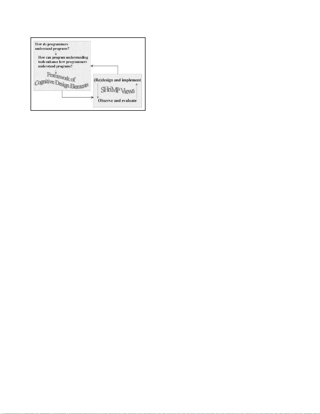
T owards a Pr ocess f or De veloping Maintenance T ools in Academia Holger M. Kienle and Hausi A. M ¨ uller Univ ersity of V ictoria V ictoria, Canada { kienle,ha usi } @cs.uv ic.ca Abstract Building of tools—fr om simple pr ototyp es to industrial- str e ngth applicatio ns—is a pervasive activity in academic r esear ch. When pr o posing a new technique for softwar e maintenan ce, effective tool sup port is typically requir ed to demo nstrate the feasibility and effectiveness of th e a p- pr o ach. However , even th ough too l building is bo th per- vasive and requiring significa nt time and effort, it is still pursued in an ad hoc manner . I n fact, little r esearc h has ad- dr essed the question how to mak e tool building in acad emia mor e disciplined , pr ed ictable and ef ficien t. In this pape r , we address these issues b y pr oposing a dedicated development pr o cess f or tool b uilding that takes the unique characteris- tics of an academic r esearc h en vir on ment into accou nt. W e first iden tify p r o cess requir ements b ased on a r eview of th e literatur e and our extensive tool building experience in th e domain of mainte nance too ls. W e th en outline a pr ocess framework based on work pr oducts tha t acc ommodate s the r equirements while pr oviding needed flexibility for tailoring the pr ocess to account for specific tool building app r o aches and pr oject co nstraints. Th e work p r o ducts ar e concrete milestones of the p r oce ss, tracking pr ogres s, rationalizing (design) decisions, and documen ting the curr ent state o f the tool building pr oject. Thus, the work pr oducts p r ovide im- portant input for strate gic pr o ject decisions and rapid initi- ation of new team members. Levera ging a ded icated tool building pr ocess pr omises too ls that a r e designe d, b uild, and maintaine d in a mo r e disciplin ed, predictable and ef- ficient manner . 1. Intr oduction T y pical research in the dom ains of software maintena nce and rev erse enginee ring proposes techniques to improve the com prehen sion of software systems. In order to eval- uate a proposed technique and to demonstrate its feasibility many research ers implemen t a tool. Such a tool can rang e from a simple proof -of-co ncept prototy pe to a fully-fled ged, industrial-stren gth application . This paper explo res the current state of tool building practices in academia with the aim to impr ove u pon the state-of-the- art. This topic is worthwh ile to address be- cause even thoug h tool building is a p opular tech nique to validate research in software en gineerin g, it is neither sim- ple no r c heap to ac complish. F or exam ple, tools such as the Rigi and Mo ose r ev erse enginee ring environments r e- quire sign ificant resour ces to develop and maintain . Rigi is now being maintain ed for over a dec ade a nd this effort has been accomplished by a n umber o f students at the Master and Ph.D. lev el as well as occasion ally b y ded icated staff members. In this c ontext the resulting con stant tu rn-over of (unexper ienced) d ev elop ers is a con cern. Nierstrasz et al., who h av e developed the Moose reeng ineering too l, ob- serve that “crafting a to ol req uires eng ineering expertise and effort, w hich consumes valuable research resou rces” [30]. The transfer of engineer ing expertise in the domain of tool building has to be addr essed within each development project. Furthermo re, it also should be addressed within the too l building comm unity in order to co mmunicate the state-of-the- art an d to fur ther im prove upon it. Cur rently , the comm unication of engineering expertise to the commu- nity is no t sufficiently rewarded: research contributions in confere nces and jour nals are me asured by n ovelty , no t by synthesis of existing w ork and exper iences. Having a pro cess when building a ma intenance tool is especially d esirable if it is a lo ng-ru nning pro ject that has a significant turnover of ( student) developers. For longe r- term research this is of ten the case. Further more, to sh ow the effecti veness of these to ols they should be sufficiently stable and matur e to ser ve in larger-scale (industrial) user studies. Building a hig h-qua lity tool without f ollowing a process exposes the research project to unnecessary risks. Improving on the curren t tool b uilding practice promises tools that are designe d, build, a nd maintained in a more disciplined, predictab le and efficient mann er . Fu rthermo re, practices can emp hasize certain non-fu nctional tool req uire- ments such as usab ility and ado ptability , or a certain ap- proach to too l building such as compon ent-based develop- ment. In this pap er we advocate to employ an explicit to ol building process to ra ise the state-of-the-a rt. This pa per is organized as follows. Section 2 gives f ur- ther b ackgro und o n tool building in academia, co ncludin g that it is executed in an ad h oc m anner an d that a suitab le process can improve upon the state-o f-the-ar t. W e explore then two more discipline d appr oaches to tool building th at have been p ursued in th e construc tion an d mainten ance of SHriMP and TkSee. Section 3 pre sents the re quiremen ts that are desirable for a tool b uilding process in an academic en viro nment. Th ese req uirements have been distilled with the h elp o f a liter ature survey as well as from ou r own tool building experiences. Th e identified requ irements can , on the o ne hand, provide impo rtant ba ckgrou nd infor mation and constraints f or d eveloping an app ropriate tool- building method, and , on th e o ther han d, serve as ev aluation criteria to judg e the e fficac y of a propo sed too l-building meth od. Section 4 is a first step tow ard s a dedicated process for building too ls. W e advocate a flexible process fram ew ork based on work pro ducts that can be easily tailored to ac- commod ate different n eeds. Importa ntly , the work produ cts that we are proposing satisfy our identified process require- ments. Section 5 closes the paper with con clusions and fu - ture work. 2. Backgr ound and Related W ork Research in tool support for software mainten ance is ac- ti vely pursued by many academics in software engineering. In th e following, we view such tools as ma intenanc e tools that offer fun ctionalities for the comp rehension and a nalysis of a target system with the goal to suppo rt engin eers in the perfor mance of mainten ance tasks. E xamples o f such tools are sof tware visualizer s, bug trackers and slicers as well as recommen der systems, search and m etrics engines. In this paper we foc us mostly on reverse eng ineering a nd g raph- based software visualization too ls beca use it is our m ain expertise and in terest. Giv en th at the constructio n of m ain- tenance tools is a p ervasi ve activity in academ ic research, surprisingly little work has focused on how tools a re built and how to improve upon the current practice. Some researchers have pub lished experiences about tool building. For example, Lanza describes his experien ces with the Cod eCrawler software v isualizer [ 22], discu ssing CodeCrawler’ s architecture (com posed of three subsystems: core, metamo del, an d visualization en gine), the visualiza- tion engine (re alized by extend ing the HotDraw f rame- work), and de sirable inter activ e mech anisms for usability . Furthermo re, he distills lesson s learned f or all of the dis- cussed issues. He observes that “to our knowledge th ere is n o explicit work abo ut the im plementation an d archi- tecture of reverse en gineerin g to ols, a nd m ore specifically about software v isualization tools. ” Gu ´ eh ´ eneuc describes his use of design pattern s and Jav a langua ge id ioms when constructing the Ptide j too l suite [ 12]. The special issue on Experim ental S of tware and T oolk its (EST) [45] of Else- vier’ s Science in C omp uter Pr ogramming jou rnal is de voted to the descriptio n of acad emic research tools. On e too l of the special iss ue, g 4 re, falls within the maintenan ce dom ain [20]. Besides the pu blished tool building experien ces dis- cussed above, researchers h av e also identified requ ire- ments fo r m aintenance and reverse en gineering tools [19, sec. 3.2 ]. For example , T ichelaar d iscusses six require ments for r eengineer ing environmen ts [43, sec. 5.1]. W ong has distilled 23 high-level an d 13 da ta requir ements fo r so ft- ware u nderstand ing and reverse eng ineering too ls [ 46]. He also recomm ends to “summarize and distill lessons lear ned from re verse engineering experience to derive req uiremen ts for the next generation of tools. ” The growing interest o f researcher s to rep ort th eir too l building experien ces is a po siti ve development th at should be furth er strengthene d within the research com munity . Howe ver , so far the focus is almost exclusi vely on docu- menting engin eering expe rtise, but not on pro cess. Un for- tunately , most r esearchers d o no t rep ort at all abou t the ir tool development p rocess. It seems that r esearchers often develop their tools by them selves and are the o nly users of the tool during and after de velopmen t. T ools are then evalu- ated with a case study or anecd otal evidence. As a result, the building of too ls resembles a craft rath er than pr ofessional engineering [34]. One appro ach to pr ofessionalize too l building is to fol- low a pro cess. Indeed, all software development projects should use a well-defin ed process—tool-building in an aca- demic environment is no exceptio n to this ru le. Acco rding to Kruchten, without such a proc ess the “development team will de velop in an ad h oc man ner, with successes relying on the heroic efforts of a few dedicated individual contr ibutors. This is not a sustainab le condition ” [21, p . 1 5]. A p rocess should p rovide gu idance on what work prod ucts sho uld be produ ced when, how , an d by whom. A well-defined process enables a r epeatable and predictab le way o f building soft- ware systems. Th ere are a fe w examples of researchers that touch on process aspects when relating their experiences. The following sections gi ve examples of tw o appro aches to tool building—SHriMP and TkSee—that can p rovide v alu- able input towards identifying process requirem ents. Th ese can in turn be used when defining a suitable pro cess for the domain of acade mic tool building. Howe ver, to our knowl- edge, n o f ull pr ocess ha s been prop osed so far . The closest research that we are aware of is Chirouze et al.’ s work on Extreme Researc hing (XR), which is a proce ss specifically designed f or applied research an d development in a dis- tributed en vir onment that has to cope with chang ing human resources an d rap id p rototypin g [5]. It is an adap tation of Extreme Programming (XP) and has been dev elop ed by Er - icsson Applied Research Laboratories to sup port distributed telecommun ications resear ch. XR is b ased o n several c ore principles taken from XP ( short d ev elop ment cycles, test- driven d ev elop ment, c ollectiv e ownership, and discipline) and e ncodes them in a set o f activities (e. g., r emote p air pr o- grammin g, unit testing , co llectiv e knowledge, codin g stan- dards, frequ ent integration, and metapho r). Dedicated too l support is av ailable for XR with a web-based portal. Based on three projects, the authors of XR estimate that their p ro- cess h as y ielded an inc rease of o utput o f aro und 24 % and reduced project-overrun time on average by half. 2.1. T o ol Building in SHriMP and TkSee The development history o f th e SHriMP p rogram com- prehen sion tool is o ne of the few m ore compr ehensive sources that allow us to infe r req uirements for tool-building. The SHriMP pro ject is an example of building a tool that has been con tinuously refined and ev aluated, following an iter ativ e appro ach of design ing and imp lementing too ls, which h as been pr oposed b y the team’ s leading professor [38, sec. 11 .1.1]. Evolving a too l such as SHriMP is a ma - jor r esearch com mitment, in volving several stud ents at the Ph.D. and master level at any gi ven time. SHr iMP had sev- eral major implem entations. The first im plementation was based on Rigi (with Tcl/Tk and C/C ++), fo llowed b y a Ja va port. The Jav a version of SHriMP was th en re-ar chitected in a c ompon ent-based te chnolog y , Jav aBeans, to facilitate closer collabor ation between r ev erse eng ineering re search group s. The Rigi-ba sed version o f SHriMP was ev aluated and improved based on two user stud ies with 12 an d 30 par- ticipants, respec ti vely [41] [4 2]. The results of both u ser studies h elped to im prove SHriMP by iden tifying sev eral shortcomin g. W u and Storey have a lso publishe d the results of their first Jav a p ort o f SHriMP; they state that “d uring the development of th is pro totype, we took in to co nsidera- tion the knowledge fro m previous prototy pes and empirical ev aluations” [47]. Even thou gh they do no t provide fur ther details, we c an inf er that their development pro cess is ( 1) prototy pe-based, (2) itera ti ve, and (3) b ased on feed back from empirical e valuations. The TkSee search tool (written in Tcl/Tk and C++) is an example of a tool that has be en improved based on th e feed- back ob tained from d ev elop ers in industry . Early versions of TkSee were deliv ere d to u sers at M itel in 199 6. At the time, the tool was u sed by relatively f ew user, which used only a small subset of its feature s. Generally , users were re- luctant to adopt ne w tools. Leth bridge and Herrera describe TkSee’ s development proce ss as follo ws [25, p. 89]: “TkSee had been de velope d in a univ ersity research en vironment follo wing an informal and opportun istic dev elopment process. Fea- tures ha d been a dded by stude nts and researc hers when they had had bright ideas they wished to expe riment with, hence it lack ed com- plete documents describing its requirement s, its design (except that of its databa se architecture [24]) and how to use it. There was con- siderabl e staf f turno ver among TkSee dev elopers bec ause man y were students. . . . The ne wer staff was often not able to understa nd the tool or the purpose of certa in features. T o im prove TkSee, feed back was o btained from field ob - servations as well as formal u ser stud ies u sing th ink-alou d protoco l and video taping. Th e results were then co mmu- nicated to th e tool developers in a repo rt an d sessions with video clips to “emphasize certain points and con vince them of th e seriou sness” of the (usability ) prob lems. Similar to SHriMP , we can conclu de that tool development had at least one iteration that improved the tool based on f eedback from a user study . Furtherm ore, the use of Tcl/Tk would facilitate rapid prototyp ing of TkSee. The approaches to tool building of both SHr iMP and Tk- See provid e valuable input to ide ntify requ irements that a dedicated process for tool building should e xhib it. 3. Pr ocess Requireme nts This section intr oduces requirem ents for a software pro- cess to develop maintenan ce tools. A d edicated develop- ment pro cess has to accommo date the p articular character- istics and constraints of the target domain . For instance, tool development in an academic research environment of- ten is ad ho c and unstruc tured. T o ols are often co nstructed by students that h av e o nly a few year s of pro grammin g ex- perience, and that typically work alone o r in sm all teams with inf ormal co mmunicatio n flow and without an explicit process. Furthermore, they often work not closely sup er- vised and are ev alua ted based on their finished prod uct, not on how they have constructed it. Researchers in th e dom ain have repor ted som e expe- riences that allow to distill p roperties that an appro priate development process sho uld pro bably possess. W e also draw from infor mal discussion s with o ther r esearchers in the ma intenance d omain, and from o ur own experien ces of developing software visualiza tion an d reverse eng ineer- ing tools. Our own experiences includ e the development and main tenance of the Rigi and Bauhau s tools as well as the tools constru cted in the context of the Adop tion-Centric Software Engineering (A CSE) project [19]. The following sections discuss the req uirements that we have been ab le to identify f or a tool building pr ocess in a n academic research setting. 3.1. Feedback-Based Many ide as for improvements of sof tware systems orig- inate from their u sers. Ther e is evidence that software d e- velopment proje cts are th e mo re successful, the more user- developer links th ey h av e [18]. Th ese links are d efined as the tec hniques or chan nels that allow users an d develop- ers to exchange inf ormation ; examples are surveys, user- interface pro totypes, requir ements prototy pes, interviews, bulletin boards, usability l abs, and observational studies. As with many other sof tware d ev elop ment pr ojects, o f- ten the research ers developing a resear ch tool have a poor initial und erstanding o f its requirem ents. Req uirements elicitation is difficult, fo r instan ce, becau se the target users are ill-defined and the tool’ s function ality mig ht be not f ully understoo d yet. T o alleviate th is p roblem and to bootstrap the first release, Sin ger and Lethbridg e pr opose to first in- volve maintenan ce en gineers (who will later use the too l) to understan d their particular needs and pr oblem domain be- fore starting the design and implementation of the tool [36]. This can be ach iev ed with q uestionnair es, ( structured) in - terviews, observation sessions, and (automa ted) logg ing of tool use. For instance, L ethbridg e and Singer have used a simple, inform al approach to elicit initial tool req uiremen ts from future users [35]: “For the first release, we brain stormed a group of softw are engine ers for their nee ds, and then designed , with th eir conti nued in volv ement, a tool calle d SEE (Softwa re Exploration Envi ronment). ” Once a research tool has reached a first beta release, feedback shou ld be obtained. Lethbridg e and Singer fo l- low a process with two main pha ses: (1 ) study a significant number o f target u sers to tho roug hly understan d the nature of their work, an d then (2 ) develop and ev alua te to ols to help the target users work better . Im portantly , the second p hase in volves “o ngoing in volvement with [target users] ” [26]. User fee dback ca n b e ob tained, f or in stance, with (long itu- dinal) work prac tice studies o f in dividuals or g roups. Such studies o bserve and recor d activities of main tainers in the ir normal work en vir onment, working on real tasks. The de- signers of the Au gur software e xp loration too l, for instance, report that “to ga in some initial feedback on Augu r’ s effec- ti veness, we have con ducted in formal evaluations with de- velopers e ngaged in ac ti ve development” [9]. Hu ndhau sen and Doug las have used the fin ding of an ethnogr aphic study with students in a course (in volving techniq ues such as par- ticipant observation, sem i-structured interviews, an d video- tape analy sis) to redefine the req uiremen ts fo r th eir algo- rithm visualization tool [16]. W on g states that “case studies, u ser experiments, and surveys a re all necessary to assess the effectiv eness of a reverse en gineerin g tool” [ 46, p. 9 3]. Many research ers condu ct in formal case st ud ies of their tools by themselves, 1 considerin g them selves as typ ical users [44]. Howev er, it is not clear whether this ap proach can gen erate th e nec- essary feedback to further im prove a to ol. A more effec- ti ve app roach is user studies. In the b est case, feedbac k is provided by the ac tual or potential futu re users of the to ol; howe ver , ob taining feedback fro m this ty pe of user is of- ten impossible. As an alter nativ e, re searchers use other— presumab ly “similar”—su bjects such as c omputer scien ce students. For examp le, Storey condu cted a study with 12 students to assess a new visualization techn ique introduced with the SHriMP tool. Observations and user comments re- sulting from the study genera ted several improvements [41, sec. 5.3]. Storey e xp lains her strategy as follo ws: 1 For instance , in a survey of twelve visualiza tion tools, two were ev al- uated with user studie s and ele ven with a case study [39]. “W e are currentl y planning further user studies to ev aluate the SHriMP and Rigi interfac es. Observ ations from these studies will be used to refine and strengthen the frame work of cognit iv e design issues which will, in turn, be used to improv e subsequent redesigns of the SHriMP interf ace” [40]. In an other user study in volving students, research ers did a sk 13 q uestions abo ut their visualization tool, sv3D, with the goal “to gather feedb ack fr om fir st time users about some of the sv3D featur es” [27]. They conclu de that the users’ “an- swers p rovided u s with valuable infor mation that su pports the implementatio n of new features in sv3D. ” T o summarize , researchers hav e tried to obtain feedb ack from different types of sub jects (e.g., professionals wh o will use the too l, studen ts who substitute for “rea l” users of th e tool, and, last but not least, themselves) as well as with d if- ferent methods (e. g., case s tud ies, field studies, surveys, and formal experiments). 3.2. Iterative Iterative so ftware development p rocesses—as oppo sed to processes that follow a waterfall or sequential strategy— are an ap proach to building sof tware in which the overall life-cycle is composed of a sequence of iterations. Boehm ’ s spiral m odel, the Rational Unified Process ( R UP), and Ex- treme Prog ramming are exam ples of iterativ e software d e- velopment pr ocesses. Dev elop ing software iteratively is among the six best practices identified by Kruchten [21]. The waterfall m odel provides minimal oppo rtunity fo r prototy ping an d iterative design [11], but “is fine for small projects that h av e f ew risks and u se a well-k nown techn ol- ogy and domain, but it cann ot be stretch ed to fit projects that are long or inv olve a high degree of n ovelty or r isk” [ 21, p. 75]. As illu strated by Rigi and SHriMP , too l-building projects can ru n for sev eral years. Sinc e research tools ty p- ically explore new id eas and striv e to advance the state-of- the-art, they are risky , potentially in volving ne w algorithm s and techniques. Th us, the w aterfall appro ach is not suitable for the development of research tools. Iterative software de velopmen t has se veral benefits com- pared to the waterfall mo del; especially imp ortant bene- fits in the con text of tool building are that user feed back is enco uraged , ma king it possible to elicit the tool’ s r eal requirem ents, and that each iteratio n results in an exe- cutable tool release th at can be ev alua ted. Gener ally , itera - ti ve development is most suitable to cope with requirements changes [23]. As in other sof tware projects, requirements in tool-building can chan ge frequen tly (e.g. , because of user- feedback and modified hypoth esis). A p articular example o f the iterative natu re of tool de- velopment is provided by the development o f a schema and correspo nding fact extractor . A schema embod ies a certain domain (e.g., C++ code or software ar chitecture), which has to be iteratively refined. Changes in the schema trig- ger change s in the fact extractor, and vice versa [29]. Figure 1. Storey’ s tool-building pr o cess [38] As an outco me o f the SHriMP tool, Storey pr oposes an iterative approach for de signing and im plementing to ols [38]. It is a p rocess consisting o f “several iter ativ e ph ases of design, development and evaluation. ” Figu re 1 dep icts a renderin g of the process iterations, illustrated with SHriMP as the sub ject. There is an “iter ativ e cycle of d esign and test” that aims at impr oving a too l [4 0]. The (initial) de- sign o f the tool is guide d b y the cog nitiv e d esign elemen ts framework, which provides a catalog of issues that should be ad dressed by software explo ration tools. T e sting o f too l design and implemen tation can be accom plished by user studies. This cycle is em bedded in a larger iter ativ e cycle for improving the framework. When adopting Storey’ s pro- cess, the larger cycle cou ld be o mitted o r rep laced with a different framework. Similar to Storey , W ong argues for an iterative appr oach when building reverse e ngineerin g to ols. He explains the process with his proposed Re verse Engineerin g Noteb ook: “The Noteboo k research itself undergoe s continuou s ev olution. The e volutio n follo ws a spiral model . . . Each iteration of the Notebook in volves se veral st ates, includ ing studies with users, e valuat ing alter- nati ve techn ologies, considering compati bility constraints and ado p- tion risks, v alidatin g the product, and planning for the next phase” [46, p. 99]. 3.3. Pr ototype -Based The co nstruction of pro totypes is commo n in engineer- ing fields (e. g., scaled- down mode ls in civil engine ering). For software constructio n, prototypin g is the “d ev elop ment of a prelimin ary v ersion of a software system in order to al- low cer tain aspects of th at system to be inv estigated ” [33]. The proto type typ ically lack s fu nctionality and does no t meet all non-f unctional req uiremen ts. Rapid pro totyping is the use of to ols or environments that sup port pro totype construction . Examp les of technolo gies that facilitate rapid prototy ping a re weakly -typed (scr ipting) lang uages with support for GUI construc tion ( e.g., Tcl/Tk and Smalltalk), tools fo r r apid app lication development (e.g., IBM’ s Lotus Notes), a nd domain- specific p rototyp ing en vir onments an d languag es (e.g., Matlab). A thro waway pro totype pro duces a cheap and rough ver- sion of the envisioned system early on in the projec t—it need not be executable an d c an be a paper simulatio n or storyboar d [4]. Su ch a p rototyp e is useful to obtain and val- idate user r equirem ents an d is then discarded once the initial requirem ents have b een established. Explor atory pro totypes are typically thro waway prototyp es that are “designed to be like a small experimen t to test a key assump tion in volving function ality or techn ology or both” [2 1, p. 161] . As op- posed to the co nstruction of a th row away prototyp e, an e vo- lutionary app roach to p rototyp ing continuou sly e volves the prototy pe into the final prod uct. Using prototyp es in software dev elop ment has a numb er of benefits. They are ef fective for de fect and r isk av oidan ce, and for u ncovering potential prob lems ( e.g., verification of the pro posed system architecture, trying out a new technol- ogy or algorithm , identification of perf ormanc e b ottlenecks, or explor ation of alternative design s) [3]. Y ang has used rapid proto typing to develop a to ol called the Ma intainer’ s Assistant; he describes se veral benefits: “There are sev eral advant ages of rapid prototyping which can be tak en to dev elop the Maintaine r’ s Assistant itself. For instance, the system can be de velop ed m uch faster by rapid prototy ping, so that it can speed up the implementati on. The user is inv olved in the pro- cess, so that he or she (mainly the builder in our system) can de- termine if the deve lopment is movin g in the right direct ion. Rapid prototyp ing produces a model of the final s ystem, so that the user , as well as builder , can see the final system in the early dev elopment stage” [48]. Prototypin g has potential drawback s also. In contr ast to a description of a system’ s b ehavior , executable proto types are well suited to r epresent what a system does. Howe ver , they ar e less well suited to capture design rationale (i.e., why was the system b uilt and why in this w ay)—th is sho uld be d ocumen ted explicitly [32]. There is also the thre at that a prototy pe th at was or iginally plan ned to b e thr own away is evolved in to the final produ ct [10]. Evolutionar y p roto- typing is th en “merely the official name given f or poor de- velopment practices where initial attemp ts at development are kept rather than thrown away and restarted ” [23]. Prototype s are well suited for ap plied research— Chirouze et al. go a s far as stating that “the idea of r apid pro - totyping and researchin g is intrinsically linked” [ 5]. W ong propo ses an itera ti ve development strategy for th e build- ing of mainten ance tools. In this a pproach , “eac h iter a- tion builds an evolutionary pr ototype that is inten ded to be a solid found ation for the next iteration” [46, p. 99]. Prototype s have b een successfu lly used in the building of software engineerin g tools (e.g., using V isual Basic [15], and Tcl/Tk [4 1]). A tool pro totype can serve as an initial proof -of-co ncept. Such a prototy pe doe s n ot n eed to fu lfill certain requir ements. For instance, a proto type can demon - strate the usefulne ss of a novel a lgorithm withou t meeting the scalability r equiremen ts of a prod uction tool. However , if user studies are b ased o n th e prototy pe, it migh t have to meet muc h higher quality standards. For example, Storey et al. report that “The first prototype of the SHriMP interfac e was implemente d in Tcl/Tk. Tcl/Tk i s a s cripti ng language and user inte rface library use- ful for rapidly prototyping graphical interfac es. Howe ver , its graph- ics capabil ities are not optimized for effic iently displayi ng the lar ge graphs typical of software systems. The second prototype has been implement ed using Pad++, a graphic s exte nsion for Tcl/Tk. Pad++ is highly optimize d for ef ficiently displaying large numbers of ob- jects and smoothly animat ing the motions of panning and zooming” [40]. 3.4. Other Requirements Based on ou r expe riences, we b eliev e tha t the f ollowing requirem ents sho uld be conside red for a too l-building pro - cess as well: lightweight: The no tion of a lightweight process is no t clearly defined . Howe ver , evidence of a lig htweight process is that it strives to min imize (interm ediate) ar tifacts su ch as vision statement, u se-case model, and status assessment, recogn izing that these artifacts are not th e goal of a process, but a means to an e nd. Martin says, “a go od process will decrease the demand for such in termediate artifacts to the barest possible minimum ” [28 ]. Extrem e Programming has four core values fro m which twe lve pr actices are derived; one of these values is simplicity [ 2]. The SEI ’ s Person al Software Process Body of Knowledge states that “a process description should be b rief and succinct” [31, Key Concept 1.1.1] . A goal of configu ring R UP is that the process “must be made as lean as possible while still fu lfilling its mission to rapidly p roduce predictably high -quality so ftware” [21, p. 31]. Cockburn intr oduces two factors that determine a method’ s weight: method size (i.e., “numb er of contr ol el- ements, includ ing deliverables, standard s, activities, m ile- stones, qu ality measu res, an d so on ”) and metho d den sity (i.e., “the detail an d c onsistency re quired in the elemen ts”) [6]. He says, “a relatively small increase in meth odolog y size or density ad ds a r elativ ely large amo unt to th e pr oject cost” [6]. Agile method s are ty pically more lightweig ht than plan-driven app roaches. component-based: Component-b ased software develop- ment (CBSD) promises lower development costs and higher productivity compar ed to imp lementing system s from scratch [ 14]. Researchers of ten rely on (off-the-shelf) compon ents and produ cts when co nstructing tools. For ex- ample, fact extractio n o f source co de h as been realized by lev erag ing Reasoning Refine, GNU GCC, Eclipse, SNIFF+ and Source Navigator, and visualizatio ns of software struc- tures have been implemen ted on to p of A T&T g aphviz, Rational Rose, Ad obe FrameMaker, Microso ft V isio, and W eb b rowsers. Howe ver , following a compone nt-based ap- proach f or too l building h as u nique cha llenges. It is nec- essary , fo r instance, to evaluate candid ate co mpon ents in terms of functionality , interoper ability , and customizability . When realizin g software visualizatio n function ality with compon ents, Lanza cautions that “ reusing g raph v isualiza- tion tools and libraries like [g raphv iz] can br eak d own the implementatio n time, but it c an also introd uce new p rob- lems like lack of control, interactivity an d c ustomizability . . . . T he first experiments we did with e xtern al engin es soon reached a limit, b ecause they wer e not cu stomizable and flexible eno ugh for o ur needs” [22]. I n o rder to meet such challenges, a pr ocess should explicitly address CBSD is- sues. adaptive: A pro cess sho uld b e flexible en ough to ac- commod ate chan ging requireme nts o f the system und er construction . Howe ver , ev olvin g r equiremen ts—or othe r changes in business, c ustomer, or techn ological ne eds— might make it necessary to ad apt th e process itself du ring the development effort. The SEI ’ s Personal Sof tware Pro- cess Body of Knowledge states that “a quality process must be easy to learn and adapt to n ew circum stances” [3 1, Key Concept 5.1 .4]. F owler describes the adap tiv e nature of a process as follows, “ A project that begins using an adapti ve process won’t have the same process a year later . Over time, the team will fin d what works f or them, an d alter the pr o- cess to fit” [8]. A pro cess ca n be adapted after an iteration as the result of a process re view . Even thoug h we could not find explicit e vid ence for these process requirem ents in th e literatu re, we believe that they should be pa rt o f an effective tool-building appro ach in academia. 4. Pr ocess Framework for T ool Building T o a dvance the goal of an effecti ve tool building ap - proach for acade mia, it is necessary to provid e developers with a su itable development process (i.e., it has to meet th e process require ments of the p revious section). Th is process needs to encod e guid elines on how to build tools in a re- peatable and predictable way . The dilemma with proposing a process is as follows: On the one hand , we need a de velopment proc ess fo r too l build- ing; on the other h and, the individual projects seem too div erse to b e accom modated by a single, one- size-fits-all process. Each individual too l-building p roject h as its own unique ch aracteristics such as the too l’ s require ments and function ality , the degree o f technica l u ncertainty , the co m- plexity and size o f the problem , the numbe r of developers, the backg round of the d ev elop ment team, an d so on. Th is is especially the case for tool-building pro jects in academia, which can differ s ign ificantly from each other . T o resolve this dilemma, we do not define an d ma ndate a f ull process; instead we are pr oposing a pr ocess frame- work . This framework addresses the tool- building req uire- ments discussed in Section 3 , but n eeds to be instan tiated by r esearchers to acco unt for th e unique chara cteristics of their own development projects. The process fr amew or k is composed of a set of work p roducts (WPs). A WP is “ any planned , concr ete result of the de velopment process” [17]. The pr ocess f ramework’ s focu s on WPs is in spired by IBM OO TC’ s process, wh ich is described in the b ook De- veloping Object-Oriented Software: An Experien ce-Based Appr oach [17]. It focu ses on WPs because often ther e is agreemen t on what should be prod uced, but not o n how it sho uld be p roduced . The developers of the pro cess say , “it was decided that an appr oach that stand ardized on work produ cts but allowed for ind ividual choices on par ticular technique s used to pr oduce work p roduc ts was the best fit” [17, p. 4] . As a result, con crete WPs provide necessary guidanc e for tool builders witho ut u nnecessarily co nstrain- ing them. 4.1. W ork Products W e d efine seven c ore WPs that reflect impor tant stages in tool development, rangin g from requirem ents elicitation, over architecture, to pro totype constru ction. The core WPs of the p rocess f ramework address specific issues of the do- main. W e pu rposely omit m ore gen eric WPs that address issues such as implementatio n and testing. Because o f limited space we can only briefly describe each WP; a m ore detailed description of each WP is avail- able in the first author’ s dissertation [19, sec. 7. 2]. W e also giv e examp le of in teractions betwe en WPs to illustra te that WPs supp ort each oth er: o ne WP ca n pr ovide v alua ble input for another WP . Intended Development Process: This WP instantiates a suitable to ol development p rocess, which should m eet our identified pro cess requir ements an d accou nt for p roject- specific chara cteristics. For example, a project that wants to employ compon ents should reflect th is practice by ac com- modating CBSD prin ciples (such as gu idance in selecting and ad apting suitable com ponen ts, an d in assemb ling the compon ent-based system). T o suppor t these tasks, the p ro- cess fr amework alrea dy o ffers two WPs: Candidate Com- ponen ts and T ool Architecture. Functional Requirements: This work product captu res the users’ expectations o f the tool’ s function ality , provid- ing a basis for com municatio n b etween users and devel- opers, and enabling to estimate d ev elop ment effort. For maintenan ce tools, fun ctionality will entail fact extraction, analysis, and visualization. T hese func tional units are typi- cally expo sed in the tool’ s arch itecture (see T ool Ar chitec- ture WP). This WP c an also c ontain a feature list, which can be bootstrapped from tool com parisons published in the literature (e.g., [1]). Non-functional Requirements: This WP describes the tool’ s quality attributes. T ools should address important do- main requirem ents such as scalability , interoper ability , cus- tomizability , usability , a nd ado ptability . Su ch requ irements are of ten difficult to f ormalize and validate. There sho uld be a ratio nalization for each of these quality attributes on how the tool will meet them. Obtaining user feedba ck with pro- totypes (see T ec hnical and UI Pr ototype WPs) can b e used in such cases to clarify quality attributes. Candidate Components: This WP add resses the identifi- cation, assessment, and selection o f (o ff-the-shelf) com po- nents and pr oducts that can be leveraged when building the tool. T o enab le a comparison am ong cand idates, assess- ment criteria (reflecting the Fun ctional and Non- function al Requiremen ts WPs) have to be define d first. Doc umenting the ration ale for selecting a certain compon ent increases the confidenc e of the too l developers into th e assessment an d selection. No te that the selection d ecision may come to the conclusion that ther e is no suitable candida te componen t in which case the r equired fun ctionality has to be implemen ted from scratch. User Interface Prototype: Th is WP mandates the co n- struction of a UI proto type. A typical objec ti ve for a proto- type is that it sho uld be good eno ugh to e nable user inter- action and feed back; and detailed and co mplete enough to support some k ind of evaluation. Th e Fun ctional and Non- function al Requirem ents WPs can be used to identify th e tool’ s “m ain line” fun ctionalities that the prototyp e should focus on. If a can didate co mpon ent is av ailable and this compon ent o ffers scr ipting su pport then it can b e used as a rapid prototy ping environment. The d ev elop ment of the prototy pe can giv e the developers v aluable first insig hts for the actual tool development. T echnical Prototy pe: This WP is con cerned with the con- struction of a proto type to explo re issues re lated to the de- sign, implementation, an d architectur e of th e tool un der construction . Th is is in co ntrast to the UI Prototyp e WP , which is exclusively conce rned with user-interface de sign. Prototypin g can be used as a risk mitigation techniq ue to re- solve or e xplo re unc ertainties of tool development that can- not be addressed by theor etical analy sis or resear ch alone. In the context of CBSD, explor atory pro totypes are espe- cially useful to provide input f or th e Candidate Com ponen ts WP beca use pub lic info rmation ab out co mpon ents can be inaccurate, misleading, or outdated. T ool Architecture: This WP d ocumen ts th e tool’ s hig h- lev el architectur e. It is discussed in mo re detail in th e next section. The fu ll descriptio n of each WP follows a template to provide a comm on structure. This template con sists of de- scription, pu rpose, techniq ue, advice and guidance, and ref- erences to related work. In th e following section, a more complete and detailed d escription following the template is giv en . 4.2. Sample W ork Product: T oo l Ar chitecture description: The T ool Arch itecture WP c aptures the sys- tem architecture o f the tool u nder constructio n. It c an be seen as the set of e arly , glo bal design d ecisions. The ar- chitecture places constraints o n the to ol’ s design an d im- plementation . The arch itecture is often visualize d with d i- agrams, but it can also take the form of a textual descrip- tion of non- function al requ irements and der iv ed architec- tural decisions. purpose: An ar chitecture can be used to show the par ti- tioning o f th e system into comp onents; the commu nication patterns and m echanisms betwe en co mponen ts; th e nature and services of the used compon ents; etc. Without an arch i- tecture, it may be difficult to reason about tool prop erties, to commun icate its design principles to ne w project members, and to maintain its ( conceptu al) integrity . The architectur e can b e used to reason about certain Non-f unctional Require- ments o f the system (e.g., p erform ance, mo difiability , and reusability). technique: The tool’ s architectu re can be described as a conceptu al architectur e diagra m that shows th e too l’ s main compon ents. Often a sing le custom ized can didate com- ponen t im plements the function ality associated with a cer- tain tool fu nctionality (i.e., extra ctor , analyzer, visualizer, or re pository) . In the early p roject stage, a comp onent in the diagram may indicate its intended fun ctionality without revealing its realiza tion. For example, there may be a co m- ponen t that is mea nt to implement repo sitory fu nctionality . Only later on in the p roject a decision will be made ab out the natu re of the rep ository (e.g., local file s ystem , r elational database, o r XML datab ase). Still later o n, th e actu al com - ponen t may be chosen. read/write data ExtractorComponent VisualizerComponent RepositoryComponent write to read from <> <> <> <> <> <> Figure 2. A tool ar chitecture in UML Architectural diag rams ar e typ ically visualized with UML. UML stereotypes can be used to co n vey addition al mean- ing. For examp le, E gyed et al. use stereoty pes to distin- guish between < > an d <> co mpo- nents [7]. Sim ilarly , stere otypes can be used to identify th e tool co mpone nt fun ctionality . Figure 2 shows an examp le o f a tool’ s arch itecture mod eled in UML. The tool is comp osed of three comp onents. The repository compon ent expo ses an interface (shown in UML ’ s shorthan d (“lollipop”) inter face notation) to read and wr ite data. Th e extracto r and visu al- izer compon ents use this i nter face to write and read data, re- spectiv ely . Stereoty pes are used to indicate the tool compo- nent typ es, and to d istinguish between th ird-par ty and cus- tom compon ents. advice and guidance: The too l arch itecture can be effec- ti ve to assess wh ether the resulting tool meets established design p rinciples. For examp le, a co mpon ent-based sys- tem will b e more m aintainable if it minimiz es couplin g among co mpone nts and relies o n op en standard s. Boehm et al.’ s MBASE appro ach iden tifies issues—grou ped in to simplifiers and comp licators —that make the development of compo nent-based sy stems easier or harder [37]. Sim- plifiers that are reflected in the architecture include “clean, well-defined APIs” an d “a single CO TS pac kage;” co mpli- cators include “multiple, incompatible CO TS packages. ” T o come up with an arch itecture it is o ften helpfu l to reuse existing expertise in the fo rm of referenc e m odels and archi- tectures, architectural patterns, or architectu ral mechanisms [21]. Several research ers have p roposed refer ence models and architectu res fo r reverse eng ineering too ls (e.g., [ 24] [13]), which can b e u sed as a starting point to define a tool’ s architecture . references: T he OOTC process d efines System Architec- ture an d Subsystem Mo del WPs; there is also a Rejected Design Alternatives work p roduct tha t can be used to record why a certain architecture was not chosen. R UP defines two artifacts related to architecture: Software Architectur e D oc- ument and Architectura l P ro totype [21, p. 86]. 4.3. Discussion The WP oriented ap proach of th e prop osed p rocess framework has been in spired by OO TC. Ho wever , the framework’ s ind ividual WPs are n ot the same as the ones described by OO TC because they are motiv ated by the pro- cess constraints and characteristics of our domain. The pro cess framework de scribes a m inimum set of WPs. A tailored version of the framework is free to in- troduce additional ones, as approp riate. Specifically , a tool- building project that exper iments with a novel or un proven technolog y cou ld in troduce ded icated WPs to make sur e this risk is addr essed a dequately . For example, if a n ew tool wanted to employ XML databa ses as a repo sitory—an unfamiliar appro ach to th e pr oject memb ers—a Repository T echnical Pro totype WP could be defined. This WP cou ld prescribe tasks suc h as creation of a sample sche ma, and benchm arking with realistic data sets. The process fra me- work has a number of desirable characteristics: lightweight: W e have argued befo re th at a too l-building process should be lig htweight. In keeping with the require - ment of a ligh tweight process, the pro cess framework itself defines on ly a minimal set of WPs, and eac h WP should be as conc ise as possible (i.e., rather 2 –3 pa ges than 10– 20 pages). The descrip tions of the WPs in the process frame- work are also kept c oncise (a round 1000 words each) to fos- ter a rapid deployment of the process. adaptive: Ad aptiv e p rocesses are desirab le fo r tool- building projects becau se they of ten have an un stable envi- ronmen t (e.g., the com position and size of the de velopm ent team can chang e consid erably du ring its life-time). Th e WP orientation and separation of con cerns of the pro cess f rame- work “addre sses the risk of losing g round when tools, no- tations, te chniques, meth od, or process need to be adju sted by allowing us to vary them while maintaining the essence and v alue of co mpleted w or k” [17, p. 15]. tailorable: The framework is tailo rable in the sense that researchers are free to extend the process fra mew ork with their own WPs. Researcher s can also omit WPs if their tool- building approach has different process constrain ts. For in - stance, a research pro ject may wish to incorpo rate an ex- plicit traceab ility req uirement for its process, or to elimin ate the T ech nical Prototyp e WP if they have sufficient und er- standing about the technology . separation of concerns: The WP oriented app roach lea ds to a separation of con cerns: WPs are indep endent fro m tools and notation as well as development pr ocess and tech- niques. reuse: The process fram ew ork define s a reu sable set o f WPs. Th ese can b e reused by ne w team member s to rapidly understan d th e current state of a to ol project, and by other researchers to jump -start their own tool-building projects— thus, WPs can b e seen as p reserving valuable tool build- ing knowledge across projects and p eople. In the best case, WPs lea d to a situatio n where existing WPs ar e r eused whenever possible, reserving the defin ition of ne w WPs f or genuine ly new contexts [4]. 5. Conclusions and Futur e W ork In th is paper w e strive to advance academ ic tool build- ing beyo nd the craft stage. What is needed is a more predicab le app roach that provides pro cesses, techniqu es, and guidan ce to tool builders. The iden tified p rocess re- quiremen ts (i.e ., feed back-b ased, iterative, proto type-ba sed, lightweight, compo nent-ba sed, and adap tiv e) and th e out- lined proc ess fr amew or k (co nsisting o f seven cor e work produ cts) are a first step in the dir ection towards the pro- fessional engineering stage. The process framew ork specif- ically addr esses the pro cess req uirements o f the domain of maintenan ce too l building, and an aca demic environment. Impor tantly , we have groun ded the process requir ements b y analyzing the domain with a liter ature revie w of relev an t tool building e xp eriences. It is an o pen que stion wheth er the pr oposed pr ocess framework is suitable for similar do mains. I t seems likely that the process fram ew ork generalizes to the whole do - main of software eng ineering tool building and to environ- ments that are s imilar to acad emic re search such as research labs. Howev er, one sh ould be careful to jump to conclu sions without a thoro ugh investigation of th e target domain . W e hope that other research ers will in vestigate t he suitability of our process framework in their domains. In future work we want to apply o ur process fr amew or k in the co nstruction of mainten ance tools. It seem s especially promising to first use the process on Master students imple- menting a relativ ely small tool with well defined scope. The work produ cts that ar e created b y the studen ts du ring the implementatio n effort can be used to do cument progre ss, record co nstraints, and rationalize decision. Furthermore, the work prod ucts can b e used to recor d too l-building ex- periences as an e ffecti ve means to commu nicate impo rtant lesson’ s learn ed to subsequ ent gen erations of students that begin to develop tools u nder similar con straints. Lastly , we want to exp lore tool suppo rt for defin ing and ev olvin g th e process framework an d its work prod ucts. Such tool sup - port could be implemented on top of IBM Rational Method Composer . Refer ences [1] S. Ba ssil and R. K. K eller . Software visu alization tools: Survey and analysi s. 9th IEEE International W orkshop on Pr ogram Compre- hension (IWPC’01) , pages 7–17, May 2001. [2] K. Beck. Extreme Pro gramming Explained : Embrace Change . Addison-W esle y , 2000. [3] B. Boehm. Making RAD work for your project. IEEE Computer , 32(3):113– 115, Mar . 1999. [4] J. Cameron. Configurable de velopment proce sses. Communicati ons of the ACM , 45(3):72–77, Mar . 2002. [5] O. Chirouze, D. Cleary , and G. G. Mitchell. A softwa re methodol- ogy for applied research: eXtreme Researchi ng. Softwar e—Practi ce and Experienc e , 35(15):144 1–1454, Dec. 2005. [6] A. Cockburn. Select ing a project’ s methodology . IEEE Softwar e , 17(4):64–7 1, July/Aug. 2000. [7] A. Egyed, S. Johann, and R. Balzer . Data and state synchronic- ity problems while inte grating CO TS software into systems. 4th Internati onal W orkshop on Adopti on-Centric Software Engine ering (ACS E’04) , pages 69–74, May 2004. [8] M. Fowle r . The ne w methodol ogy . MartinF owler .com , Apr . 2003. http://www.mar tinfowler.com/a rticles/newMethodology.html . [9] J. Froeh lich and P . Dourish. Unifying artifa cts and acti vities in a vi- sual tool for di stributed software de velopment . 26th AC M/IEEE In- ternati onal Confer ence on Softwar e Engineerin g (ICSE’04) , pages 387–396, May 2004. [10] V . S. Gordon and J . M. Bieman. Rapid prototyping: Lessons learne d. IEEE Softwar e , 12(1):85–95, Jan. 1995. [11] J. Grudin. Interac tiv e systems: Bridging the gaps between de velop- ers and users. IEE E Comput er , 24(4):59–69, Apr . 1991. [12] Y .-G. Gu ´ eh ´ eneuc. Ptidej: Promoting patterns with patterns. 1st ECOOP workshop on Building a System using P atterns , July 2005. http://www.iro .umontreal.ca/ ˜ ptidej/Publica tions/Documents /ECOOP05BSUP.do c.pdf . [13] J. Hainaut, V . Englebert , J. He nrard, J.-M. Hi ck, and D. R oland. Re- quirement s for informat ion system reve rse enginee ring support. 2nd IEEE W orking Confer ence on Reverse Engineering (WCRE’95) , pages 136–145, July 1995. [14] G. T . Heineman and W . T . Councill. Compone nt-Based Softwar e Engineerin g: Putting the Pieces T oget her . Addison-W esle y , 2001. [15] M. E. C. Hu ll, P . N. N icholl , P . Houston, and N. R ooney . T ow ards a visual approach for component-ba sed software de velopment . Soft- war e – Concepts & T ools , 19(4):154–160, Aug. 2000. [16] C. Hundhausen and S. Douglas. A language and system for con- structin g and presenting lo w fi delit y algorithm visualizati ons. In S. Diehl, editor , Softwar e V isualization , volume 2269 of Lecture Notes in Comput er Science , pages 227–240 . Springer-V erlag, 2002. [17] IBM Object-Orie nted T echnology Cente r . Deve loping Object- Oriented Softwar e: An Experience-Based Approac h . Prentice Hall, 1997. [18] M. Kei l and E. Carmel. Customer-d ev eloper links in software de- vel opment. Communications of the ACM , 38(5):33–44, May 1995. [19] H. M. Kienle. Building Rever se Engin eering T ools with Softwar e Compon ents . PhD t hesis, Dep artment of Computer Science, Univ ersity of V ictoria, Nov . 2006. https://dspace .library.uvic.c a:8443/dspace/h andle/1828/115 . [20] N. A. Kraft, B. A. Malloy , and J. F . Po wer . A tool chain for reve rse enginee ring c++ appli cations. Science of Computer P r ogrammin g , 69(1–3):3– 13, Dec. 2007. [21] P . Kruchten . The Rational Unified Pr ocess: an intr oduction . Object T echnology Series. Addison-W esley , 1999. [22] M. Lanza. Codecrawl er—lessons learned in building a software vi- sualiza tion tool. 7th IEEE Europ ean Confer ence on Sof tware Mai n- tenance and Reengineeri ng (CSMR’03) , pages 1–10, Mar . 2003. [23] P . A. Lapla nte and C. J. Neill . Opinion: The demise of the w aterfa ll model is imminent. ACM Queue , 1(10):10–1 5, Feb . 2004. [24] T . C. Let hbridge and N. Anque til. Architec ture of a source cod e ex- plorati on tool: A softwa re enginee ring case study . T echnical Report TR-97-07, Univ ersity of Ottawa , Computer Science , 1997. [25] T . C. Let hbridge and F . Herrera. Assessing t he useful ness of the TK- See software e xploratio n tool. In H. Erdogmus and O. T anir , edi tors, Advances in Sof tware Enginee ring: T opics in Comp rehensi on, E vo- lution, and Evaluatio n , chapter 11, pages 73–93. Springer -V erla g, Dec. 2001. [26] T . C. Lethbridge and J. Singer . Strate gies for studying m ainte - nance. 2nd W orkshop on Empirical Studies of Softwar e Mainte- nance (WESS’96) , pages 79–83, Nov . 1996. [27] A. Marcus, D. Comorski, and A. Ser geye v . Supporting the e volution of a software v isualizati on tool throug h usability studie s. 13th IEEE Internati onal W orkshop on P r ogram Compr ehension (IWPC’05) , pages 307–316, May 2005. [28] R. C. Martin. R UP vs. XP. object mentor .com , 2001. http://www.obj ectmentor.com/r esources/articl es/RUPvsXP.pdf . [29] D. L. Moise and K. W ong. Issues in integrati ng schemas for re- verse engineerin g. In J.-M. Favre, M. Godfrey , and A. Win ter , edi- tors, International W orkshop on Meta-Models and Schemas for R e- verse Engineering (ateM’03) , volu me 94, pages 81–91. Elsevier , May 2004. [30] O. Nie rstrasz, S. Ducasse, and T . G ˆ ırba. The story of Moose: an ag- ile reengine ering en vironment. 10th Europe an Software E ngineer - ing Confer ence held jointly with 13th ACM SIGSOFT Internat ional Symposium on F oundat ions of Softwar e E nginee ring (ESE C/FSE- 13) , pages 1–10, Sept. 2005. [31] M. Pomeroy-Hu ff, J. Mullane y , R. Cannon, and M. Se- bern. The personal softw are proce ss(psp) body of kno wl- edge. Special Report CMU/SEI-2005-SR-003 , Softw are Engineeri ng Instit ute, Carnegie Mellon Univ ersity , Aug. 2005. http://www.sei .cmu.edu/pub/do cuments/05.repo rts/pdf/05sr003.pdf . [32] K. Schnei der . Prototyp es as assets, not toys: Why and how to extract kno wledge from prototype s. 18t h ACM /IEEE International Con- fer ence on Software Engineering (ICSE’96) , pages 522–531, May 1996. [33] R. Schwan inger . Rapid prototyping with Tcl/Tk. Linux J ournal , May 1998. http://www.lin uxjournal.com/a rticle/2172 . [34] M. Shaw . P rospects for an eng ineering discipline of software. IEEE Softwar e , 7(6):15–2 4, Nov . 1990. [35] J. Singer and T . Lethbridge. Studying work practic es to assist tool design in softwa re engineering. 6th IEEE International W ork- shop on Pr ogram Comprehensi on (IWPC’98) , pages 173–179 , June 1998. [36] J. Singer , T . Lethbridge, N. Vi nson, and N. Anquetil. An examina- tion of softw are engineeri ng work pr actices. Confer ence of the Cen- tr e for Advanced Studie s on Collabor ative Researc h (CASCON’97) , pages 209–223, Nov . 1997. [37] I. Sommerville. Integrat ed requiremen ts engineeri ng: A tutorial. IEEE Softw are , 22(1):16–23, Jan./Feb . 2005. [38] M.-A. D. Store y . A Cognitiv e F ramew ork for Describing and Eval- uating Software E xplor ation T ools . PhD thesis, Simon Fraser Uni- versi ty , Dec. 1998. [39] M. D. Sto rey , D. Cubranic, and D. M. German. On th e use of vi sual- izati on to support aw areness of human activi ties in software dev el- opment: A survey and a framew ork. ACM Symposium on Softwa re visuali zation (SoftV is’05) , pages 193–202, May 2005. [40] M. D. Store y , F . D. Fracchia , and H. A. M ¨ ulle r . Cogniti ve design element s to support the construction of a mental model during soft- ware explorati on. Journal of S ystems and Softwa re , 44(3):171 –185, Jan. 1999. [41] M. D. Store y , K. W ong, P . Fong, D. Hooper , K. Hopkins, and H. A. M ¨ ulle r . On design ing an experiment to ev aluat e a rev erse engineer- ing tool. 3rd IEEE W orking Confer ence on Rever se Engineerin g (WCRE’96) , page s 31–40, Nov . 1996. [42] M. D. Storey , K. W ong, and H. A. M ¨ ulle r . Ho w do program un- derstandi ng tools af fect ho w programmers understand programs. 4th IE EE W orking Conf erenc e on Rev erse Engine ering (WCRE’97) , pages 12–21, Oct. 1997. [43] S. T ichela ar . Modeling Object -Oriented Softwar e for Reverse Engi - neering and Refact oring . PhD thesis, Uni versit ¨ at Bern, Dec. 2001. [44] M. A. T oleman and J. W elsh. Systematic ev aluation of design choice s for software deve lopment tools. Softwar e – Concepts & T ools , 19(3): 109–121, 1998. [45] M. van den Brand. Guest editor s introduction : Experimental soft- ware and toolkit s (E ST). Scien ce of Computer Pr ogrammi ng , 69(1– 3):1–2, Dec. 2007. [46] K. W ong. The Reverse Engineering Notebook . PhD thesis, Depart- ment of Computer Scien ce, Uni versity of V ictori a, 1999. [47] J. W u and M. D. Store y . A multi-perspect iv e softwa re visualizat ion en vironment. Confe rence of the Centr e for Advanced Studies on Collabor ative R esear ch (CASCON’00) , pages 15–24, Oct. 2000. [48] H. Y ang. The supporting env ironment for a rev erse engineeri ng system—the maintainer’ s assistant. Confere nce on Softwar e Main- tenance (CMS’91) , pages 13–22, Oct. 1991. This wor k is li censed under a Cr eative Co mmons Att ribution-Non commercial- Share Alike 3.0 United States License. The license is available here: http://creativecommons. org/licenses/by- nc- sa /3.0/us/ .
Original Paper
Loading high-quality paper...
Comments & Academic Discussion
Loading comments...
Leave a Comment