Performance Analysis of a Cross-layer Collaborative Beamforming Approach in the Presence of Channel and Phase Errors
Collaborative beamforming enables nodes in a wireless network to transmit a common message over long distances in an energy efficient fashion. However, the process of making available the same message to all collaborating nodes introduces delays. The…
Authors: Lun Dong, Athina P. Petropulu, H. Vincent Poor
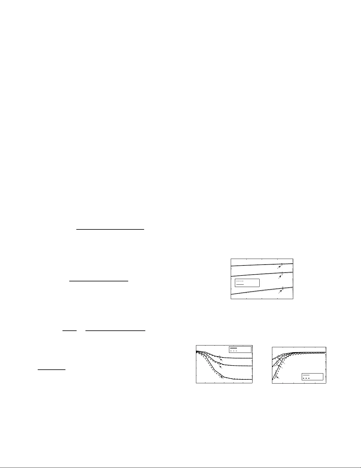
PERFORMANCE ANAL YSIS OF A CR OSS-LA YER CO LLABORA TIVE BEAMFORMING APPR O A CH IN THE PRESENCE OF CHANNEL AND PHASE ERR ORS Lun Dong, Athina P . P etr opulu Dept. of Electrical & Computer Engineering Drex el Uni versity , Philadelphia, P A 1 9104 H. V in cent P oor School of Engineering & Applied Science Princeton Univ ersity , Princeton, NJ 08544 ABSTRA CT Collaborative beamfor ming enables n odes in a wir eless net- work to transmit a com mon message over lon g distances in an energy efficient fashion. Ho wever , the p rocess of making av ailab le the same message to all collab orating nodes introduc es de lays. T he auth ors recen tly pro posed a MA C-PHY cross-layer scheme that enables collabo rativ e beamfor ming with significantly reduced collab oration over- head. Th e method r equires knowledge o f nod e locations and internod e channel coefficients. In th is paper , the perf ormance of th at app roach is studied analytica lly in terms of a verag e beampatter n and symbol er ror p robability (SEP) under real- istic con ditions, i.e., wh en imperfect channel estimates are used and when the re a re phase erro rs in the contributions o f the collaborating nodes at the receiver . Index T erms — collaborative beam forming , cr oss-layer approa ch for wireless network s, imp erfect conditions I. INTRODUCTION Distributed, or collabor ati ve, b eamformin g has b een of considerab le recen t interest as a p referred solution f or lon g- distance transmission in wireless network s, due to its en ergy efficiency [2],[3]. In conventional distributed beam forming schemes, a set of distrib ute d nodes (c alled collaborating nodes) act as a virtual an tenna array an d form a beam to cooper ati vely transmit a common si gnal arising from a source node. Using knowledge of ne twork coo rdinates, each co l- laborating node adjusts its initial phase so that the resu lting beampatter n foc uses in the d irection o f the desired d esti- nation. The requ irement that all co llaborating node s have access to the sam e message signal means that sourc e no des must share their message signals with collabor ating no des before beamfo rming. T o study network p erforma nce, one must take into acco unt the overhead (infor mation-shar ing time) requir ed fo r node collabo ration. If a time-division multiple-acce ss ( TDMA) sch eme were to be e mployed, the informa tion-sharing time would incr ease p roportio nally to the number of source node s. This work was supported by the National Scienc e Foundatio n under Grants ANI-03-38807, CNS-06-25637 and CNS-04-35052, and by the Offic e of Nav al Research under Grant ONR-N00014-07-1-05 00. The au thors r ecently pro posed a MA C-PHY cro ss-layer technique in [ 1] and [4], based on the id ea of collab orative beamfor ming of [3], to r educe the time r equired fo r infor- mation sh aring an d to allow simultaneou s multiple b eams. The main id ea is a s follows: for info rmation-sh aring, we consider a real p hysical mo del in wh ich collabor ating node s receive linear m ixtures o f transmitted packets. Subsequ ently , each collab orating node transmits a weig hted version of its received signal. The weig hts allow packets bou nd to the same destination to add coheren tly at the destination n ode. Each collabo rating node comp utes its weig ht based on the estimated chann el co efficients between sour ces an d itself, and also based on estimates of node coordinates. In [1] and [4] the an alysis was perfo rmed und er the assumption that all required estimates are perfect. In this paper, we in vestigate perfor mance under imperfect cond itions, i.e ., when ther e are channel estimation errors and phase erro rs. II. SYSTEM MODEL AND PROPOSED SCHEME The no tation used here is illustra ted in Fig. 1. For simplic- ity , let us assum e th at sou rces and destinatio ns ar e c oplanar . The netw ork is di vided into clusters, so that nodes in a cluster can hear each other’ s transmissions. During slot n , source nodes t 1 , . . . , t K in cluster C tend to commun icate with nodes q 1 , . . . , q K that belong to clusters C 1 , . . . , C K , respec- ti vely . The beam forming is perfor med by nodes in cluster C . The N collabo rating nodes, design ated as c 1 , . . . , c N , are assumed to be unif ormly d istributed over a disk of radiu s R . W e deno te the locatio n of c i in p olar coordin ates with respect to the origin of the disk by ( r i , ψ i ) . Let d im represent the distanc e between c i and th e destination q m , and d 0 m represent the distance between the origin o f the disk an d q m . If φ m is the azimuthal angle of q m with resp ect to the origin of the disk, the polar coordin ates of q m are ( d 0 m , φ m ) . Moreover , let d i ( φ ) denote the distance between c i and some receiving p oint with polar coordin ate ( d 0 m , φ ) . W e furthe r make the following assumption s: (1) A slotted packet system is con sidered, in which each packet requir es one slot for its transmission. Perfect synchronization is as- sumed be tween node s in the same cluster . Nodes opera te un- der half-du plex mode, i.e., they cannot receiv e while they are m t m q i c a a a a collaborating node source node destination node cluster head 0 m d R Far Field: ! R idle node a a im d a a a 0 m d i r R r i i m ! a a a 0 m d a a a ( ) i d ! ! Fig. 1 . I llustration of notation. transmitting. (2) Nodes transmit packets consisting of ph ase- shift keying (PSK) sy mbols e ach having the same power σ 2 s . (3) Co mmunication takes place over flat fading chann els. The chann el g ain dur ing slot n b etween source t i and collaboratin g node c j is denote d by a ij ( n ) . For intra-cluster commun ications small-scale fading p lays the dom inant r ole. Thus, for a fixed n , we mo del a ij ( n ) as circularly symmetr ic complex Gaussian rando m variables with zer o mean s an d variances σ 2 a (i.e., th is is a Rayleigh fadin g model). The gains of d ifferent paths are assumed to be independent and identically distributed (i.i.d.). The gain of a given path is constant durin g the slot du ration. (4) For inter-cluster c om- munication s, large-scale fading p lays th e d ominant role. W e assume that the distances between collabor ating n odes and destinations are much g reater than the max imum d istance between source and collaborating no des. Th us, the complex baseband- equiv a lent channel gain between nodes c i and q m during beamfor ming equ als b m e j 2 π λ d im [6], where λ is the signal wa velength and b m is the path loss between the center o f the disk co ntaining the co llaborating n odes and the destination. In slot n , a ll source n odes within the clu ster C simultane- ously transmit th eir packets. Th e packet transm itted by n ode t j consists of L symbo ls s j ( n ) , [ s j ( n ; 0) , . . . , s j ( n ; L − 1)] . Due to the br oadcast natur e of the wireless chan nel, non - activ e nodes in cluster C hear a collision, i.e., a linear combinatio n of the tran smitted symbols. More specifically , node c i hears the signal x i ( n ) = K X j =1 a j i ( n ) s j ( n ) + w i ( n ) (1) where w i ( n ) = [ w i ( n ; 0) , . . . , w i ( n ; L − 1)] represen ts noise at the receiving n ode c i . The noise is assumed to be zer o- mean with covariance matrix σ 2 w I L , wh ere I L denotes the L × L identity matrix . Suppose that in slot n + m, m = 1 , . . . , K , th e collab- orating no des need to beamfo rm s m ( n ) to d estination q m . Each collabor ating no de c i transmits the signal ˜ x i ( n + m ) = x i ( n ) µ m a ∗ mi ( n ) e − j 2 π λ d im (2) where e − j 2 π λ d im is the initial phase o f c i . µ m is a scalar used to adjust the transmit power; it is the sam e for a ll collaboratin g no des, and is on the order of 1 / N . Giv e n the collab orating no des at ra dial co ordinates r = [ r 1 , ..., r N ] and a zimuthal coordinates ψ = [ ψ 1 , ..., ψ N ] , the received signal at an arbitrary location with polar coordinates ( d 0 m , φ ) , is y ( φ ; m | r , ψ ) = N X i =1 b m ˜ x i ( n + m ) e j 2 π λ d i ( φ ) + v ( n + m ) (3) where v ( n + m ) re presents no ise at the receiv er during slo t n + m . The covariance ma trix of v ( n + m ) equals σ 2 v I L . The received signal at the destination q m during slot n + m is y ( φ m ; m | r , ψ ) = N X i =1 b m ˜ x i ( n + m ) + v m ( n + m ) . (4) It was shown in [4] that, as N → ∞ an d omitting the noise, y ( φ m ; m | r , ψ ) → N µ m b m σ 2 a s m ( n ) . Thus, the destination node q m receives a scaled version of s m ( n ) . The beamfor ming step is completed in K slots, reinfor cing one source signal at a time. C ompared with the scheme in [3], the informa tion sharing time is r educed f rom K to 1. Multip le beams can be fo rmed in on e slot w hen source p ackets have distinct d estinations. In the r est of the p aper , for simp licity we will con sider only the case in wh ich a single be am is formed durin g slot n + m , focusing on de stination q m . III. A VERA G E BEAMP A T TERN UNDER IMPERFECT CONDITIONS The beamp attern rep resents the distribution of received power a long all azimuth al angles. W e showed in [4 ] that, under perfect con ditions the average b eampattern is of a form similar to [3], with increased sidelo be level. In th is section, we discuss effects of imperfect channels and phase on av erage beampattern, respectiv e ly . III-A. Imperfect Channels W e mod el ˆ a mi = a mi + δ a mi as the imperfect estimate of a mi , where δ a mi is the estima tion erro r . Th e estima- tion erro rs ar e i.i.d. Gaussian ran dom variables, δ a mi ∼ C N (0 , σ 2 δ ) . Th e average beam pattern with imp erfect ch an- nels can be expressed as ˜ P av ( φ ) = E { | y ( φ ; m | r , ψ ) | 2 } = P av ( φ ) + δ P av ( φ ) (5) where P av ( φ ) is the a verage beampattern related to pe rfect channels a mi , and δ P av ( φ ) is the average beampattern related to the estimation erro r δ a mi . Following steps similar to those leading to P av ( φ ) in [4], on e ca n obtain δ P av ( φ ) = µ 2 m b 2 m E ( | s m | 2 N X i =1 | a mi | 2 | δ a mi | 2 + K X j =1 j 6 = m | s j | 2 N X i =1 | δ a mi | 2 | a j i | 2 + N X i =1 | δ a mi | 2 | w i | 2 ) = N 2 µ 2 m b 2 m σ 2 s σ 4 a K σ 2 δ N σ 2 a + σ 2 δ N γ 1 σ 2 a ∝ σ 2 δ σ 2 a (6) where γ 1 △ = σ 2 s σ 2 a /σ 2 w represents the average SNR at the collaboratin g nodes. Note that δ P av ( φ ) is a ctually a con stant indepen dent of φ . I n other words, the effect of imper fect channels on av erage b eampattern is an increased side lobe lev el. III-B. Imperfect Phase Under imperfe ct p hase, each c ollaborating node c i will transmit the signal ˜ x i ( n + m ) e j τ i , where the τ i represents the phase err or , which is assumed i.i.d. with respect to i . W e use the same model as in [3] for the phase erro rs. Regarding how to o btain th e initial phase, two cases ( closed-loop an d open-lo op) are conside red (see [3] for details): (1) For the closed- loop case, imperfe ct phase corresp onds to the phase offset due to th e p hase am biguity caused by carrier phase jitter or offset b etween the transmitter and receiver node s. W e assume that the phase err or τ fo llows a T ik honov d istribution, wh ich is a typ ical phase jitter model for phase-locked loop (PLL) circuits. (2) F or the open -loop case, imperfect p hase results fro m estimation error s in the locatio n parameters r i and ψ i . W e assume the co rrespond ing radius error δ r i is uniform ly distributed over [ − r max , r max ] , and th e an gle erro r δ ψ i is unifor mly distributed over [ − ψ max , ψ max ] . The rad ius and angle erro rs are fu rther assumed to be mutually indepen dent random variables, in depende nt of r i and ψ i . Based on th e above phase er ror mod els, we can show that the expr essions of the average beamp attern are similar to the results in Section VI of [3] with the only difference being a scaling factor . T hus, as in [3], the b asic e ffect of these phase er rors is in redu cing the power in the main lobe. The deriv a tion is similar to th at in [ 3] an d is o mitted here due to space limitations. IV . SEP UNDER IMPERFECT CONDITIONS Under perf ect condition s, the received signal (one samp le) at the destination is given by y ( φ m ; m ) = µ m b m N X i =1 | a mi | 2 s m + µ m b m N X i =1 a ∗ mi η i + v , (7) where η i , P K j =1 j 6 = m a j i s j + w i . W e sho wed in [1] that η i ∼ C N 0 , σ 2 η where σ 2 η , ( K − 1) σ 2 a σ 2 s + σ 2 w . Giv e n a mi , th e instantaneo us signal-to-interf erence-p lus- noise ratio (SINR), γ , equals γ = µ 2 m b 2 m σ 2 s ξ 2 µ 2 m b 2 m σ 2 η ξ + σ 2 v (8) where ξ △ = P N i =1 | a mi | 2 follows an Erlang distribution ( ξ ∼ Erlang( N , σ 2 a ) ). Giv e n K , the SEP for M-PSK symbo ls u nder perfect condition s is [1], [5] P s ( K ) = 1 π Z ( M − 1) π M 0 Z ∞ 0 exp − sin 2 ( π / M ) sin 2 ϕ · γ × ξ N − 1 e − ξ σ 2 a σ 2 N a ( N − 1)! dξ dϕ . (9) IV -A. Imperfec t Channels T aking channel err ors into accou nt, the received signal at the destination is given by y ( φ m ; m ) = µ m b m N X i =1 | a mi | 2 s m + µ m b m N X i =1 a mi δ a ∗ mi s m + µ m b m N X i =1 ( a ∗ mi + δ a ∗ mi ) η i + v . (10) Since the destinatio n n ode does n ot h a ve knowledge of δ a mi , the term µ m b m P N i =1 a mi δ a ∗ mi s m represents in - terference . Th us, in the interfere nce term, a mi and δ a mi are coupled together, and th e exact SEP would inv olve integration of all of the 2 N random variables ( a mi and δ a mi , i = 1 , . . . , N ). In the sequ el we will use an app roximation that simplifies this analysis. Let us define κ = µ m b m N X i =1 [ a mi δ a ∗ mi s m + ( a ∗ mi + δ a ∗ mi ) η i ] . (11) It is easy to show th at, given a mi , E { κ } = 0 and σ 2 κ = E { | κ | 2 } = µ 2 m b 2 m ( σ 2 η + σ 2 s σ 2 δ ) ξ + µ 2 m b 2 m σ 2 η N σ 2 δ . (12) According to the centra l limit theorem , when N is large, κ is approx imately normally distributed. Let us thus ap proxima te the distribution of κ as κ ∼ C N (0 , σ 2 κ ) . T aking into a ccount the indepen dence of κ and v , the app roximate instantaneo us SINR, γ ch , equals γ ch = µ 2 m b 2 m σ 2 s ξ 2 µ 2 m b 2 m ( σ 2 η + σ 2 s σ 2 δ ) ξ + µ 2 m b 2 m σ 2 η N σ 2 δ + σ 2 v (13) which con tains only a single ran dom variable ξ . Finally , to calculate th e SEP u nder imperfect ch annel condition s, let u s substitute γ ch for γ in (9). The techniqu es in section IV -A of [1] can be used to obtain simple b ounds for SEP . Simulation : Fig. 2 shows the SEP versu s σ 2 δ /σ 2 a . As expected, SEP increases with inc reasing σ 2 δ . The analytica l result based on (13) m atches well expe rimental r esults for a wide range of values of σ 2 δ . IV -B. Imperfect Phase Imperf ect phase has two effects on th e receiver: signal power reduc tion and phase distortio n [2]. Assumin g that the phase d istortion is compen sated for by the co herent receiver (e.g., by pilots), h ere we fo cus on signal p ower reductio n only . W e define the power reduction coefficient A τ = P err /P ideal ≤ 1 , where P err is the a verage received signal power with phase error and P ideal is the average signal power under perfect phase. T aking p hase errors into acco unt, the rece i ved signal at the destination is given by y ( φ m ; m ) = µ m b m N X i =1 | a mi | 2 e j τ i s m + µ m b m N X i =1 a ∗ mi η i e j τ i + v , (14) where τ i is the phase error of collab orating node c i . Note that the statistics of η i e j τ i are the same as those of η i ; so phase errors do not change th e statistical beha vior of the interferenc e term . Assuming we use a coh erent receiver , the in stantaneous SINR, γ ph , equals γ ph = µ 2 m b 2 m σ 2 s | P N i =1 | a mi | 2 e j τ i | 2 µ 2 m b 2 m σ 2 η ξ + σ 2 v . (15) Since | a mi | 2 and e j τ i are cou pled, the exact SEP inc ludes integration with r espect to a mi and τ i ( i = 1 , . . . , N ), which is comp utationally complex. T o facilitate analysis we m ake the following ap proximatio n for γ ph : γ ph ≈ A τ · µ 2 m b 2 m σ 2 s ( P N i =1 | a mi | 2 ) 2 µ 2 m b 2 m σ 2 η ξ + σ 2 v = A τ · γ . (16) In o ther word s, γ ph is appro ximated by the instantaneo us SINR u nder perf ect cond itions scaled do wn by a coef ficient A τ . It can be shown that A τ = P err P ideal = 2 + ( N − 1) E e j τ i 2 N + 1 , (17) where E e j τ i 2 depend s on the specific phase error model used. Based on the ph ase erro r models in section III-B, E e j τ i 2 has been derived in [3]. Simulation : In Fig. 3(a), we show the SEP as a function of loop SNR ρ τ (closed-loo p case). The v ar iance of the phase error is 1 / ρ τ . For the analy tical SEP , we directly use the results in [3] to calculate E e j τ i 2 and obtain A τ in (1 7). As observed, ρ τ > 10 dB may be necessary to achieve a satisfactory SEP . Fig. 3 (b) sho ws the SEP vs. r max /R and ψ max / (2 π ) (open-lo op case), where both radius and ang le errors ar e c onsidered. One c an see that th e ph ase erro r in th e open-lo op case can se verely degrade the SEP pe rforman ce. Thus, it is importan t to investigate techniqu es that en able accurate location estimation . In both figu res, the analytical result based on (16) match we ll the experimental results fo r a wide range of phase erro rs. V . CONCLUSIONS W e have considered the cro ss-layer collabo rativ e beam- forming ap proach of [1] an d [4], and we h av e analyzed its per formanc e und er imperfect co nditions. For th e average beampatter n, the p rincipal e ffect of imperfect cha nnel infor- mation is increased sidelobe level, and th e princip al effect of im perfect phase information is reduced mainlob e power . W e have provided approxim ate analytical e xpressions for th e SEP u nder imp erfect con ditions, which show the ef f ects of imperfect channel and phase on that quan tity . VI. REFERENCES [1] L. Dong, A. P . Petropulu and H. V . Poor, “Coope rati ve beamforming for wireless ad hoc networks, ” in Proc. 2007 IEEE Global Commun. Conf . , W ashington, DC, Nov . 2007. [2] R. Mudumbai, G. Barriac and U. Madhow , “On the feasibilit y of distrib uted be amforming in wireless netwo rks, ” IEEE T rans. W irele ss Commun , vol. 6, no. 5, pp. 1754-1763, May 2007. [3] H. Ochiai, P . Mitran, H. V . Poor and V . T arokh, “Collabora ti ve beamforming for distrib uted wireless ad hoc sensor network s, ” IEEE T rans. Signal Pr ocess. , vol . 53, no. 11, pp. 4110 - 4124, Nov . 2005. [4] A. P . Petropulu, L. Dong and H. V . Poor, “ A high-throughput cross- layer scheme for distribute d wireless ad hoc networks, ” in Pr oc. 41st Conf . Inform. Sci. Syst. , Baltimore, MD, Mar . 2007. [5] M. K. Simon and M.-S. Alouini , Digital Communication over F ading Channel s (second edition ). John W ile y & Sons, New Y ork, 2005. [6] D. Tse and P . V iswanath , Fundame ntals of W ire less Communicat ion. Cambridge Uni v Press, Cambridge, UK, 2005. 0 5 10 15 20 10 −5 10 −4 10 −3 10 −2 10 −1 σ δ 2 / σ a 2 (%) SEP experimental analytical N=8 N=16 N=32 Fig. 2 . SEP under imperfect channels. K = 4 , γ 1 = 20 dB, γ 2 , N 2 µ 2 m b 2 m σ 2 s σ 4 a /σ 2 v = 20 dB, BPSK symbo ls. −5 0 5 10 15 20 25 10 −5 10 −4 10 −3 10 −2 10 −1 10 0 Loop SNR ρ τ (dB) SEP experimental analytical N=8 N=16 N=32 (a) closed-loo p 0 1 2 3 4 5 10 −5 10 −4 10 −3 10 −2 10 −1 10 0 r max /R (%) and ψ max /2 π (%) SEP experimental analytical N=32 N=16 N=8 (b) open- loop Fig. 3 . SEP under imperfect phase. R = 10 λ , K = 4 , γ 1 = 20 dB, γ 2 , N 2 µ 2 m b 2 m σ 2 s σ 4 a /σ 2 v = 20 dB, BPSK symbo ls.
Original Paper
Loading high-quality paper...
Comments & Academic Discussion
Loading comments...
Leave a Comment